
Related Manuals for Lycoming TEO-540-A1A


Summary of Contents for Lycoming TEO-540-A1A
- Page 1 Engine Installation and Operation Manual TEO-540-A1A Engine October 2018 Part No. IOM-TEO-540-A1A © 2018 Avco Corporation. All Rights Reserved...
- Page 2 Visit us Online: www.lycoming.com NOTE: Lycoming recommends that owners of this manual sign up for email notification on the Technical Publications page of our website https://www.lycoming.com/contact/knowledge-base/publications. By submitting your email address, you will receive notification whenever Lycoming publishes a new or revised technical publication, including any revisions to this Engine Installation and Operation Manual.
-
Page 3: Record Of Revisions
TEO-540-A1A Engine Installation and Operation Manual RECORD OF REVISIONS Revision Revised Revision Date Revision Description Original Original Release of Installation and Operation Manual - Part No. IOM-TEO-540-A1A © 2018 Avco Corporation. All Rights Reserved Record of Revisions October 2018 Page i... - Page 4 TEO-540-A1A Engine Installation and Operation Manual This page intentionally left blank. Record of Revisions © 2018 Avco Corporation. All Rights Reserved Page ii October 2018...
-
Page 5: Service Document List
10/18 Engine Inspection in a Particulate Laden Environment (Volcanic Ash, Sand, Dust, Airborne Debris) S.I. 1566 10/18 Lycoming Engines Approves the Use of Safety Cable S.I. 1573 10/18 Lycoming TEO-540 Engine Series Engine Control Unit (ECU) Assembly Cross-References Reciprocating Engine and Accessory Maintenance... - Page 6 TEO-540-A1A Engine Installation and Operation Manual This page intentionally left blank. Service Document List © 2018 Avco Corporation. All Rights Reserved Page iv October 2018...
-
Page 7: Table Of Contents
TEO-540-A1A Engine Installation and Operation Manual TABLE OF CONTENTS Section Page Frontal __________________________________________________________________________ Record of Revisions ..........................i Service Document List ........................iii Table of Contents ..........................v List of Figures ............................. ix List of Tables ............................xi Abbreviations and Acronyms ...................... - Page 8 TEO-540-A1A Engine Installation and Operation Manual Section Page Theory of Operation ______________________________________________________________ — EECS Operation ........................15 — Engine Control Sequence ......................16 — Engine Synchronization ......................16 — Fuel Control ..........................16 — Ignition Control ........................16 — Load Sensing ...........................
- Page 9 TEO-540-A1A Engine Installation and Operation Manual Section Page Engine Installation ________________________________________________________________ — Engine Installation Overview ....................33 — Step-1. Install the ECU ......................34 — Step-2. Install the Power Box ....................34 — Step-3. Install the Engine on Mounts ..................34 —...
- Page 10 TEO-540-A1A Engine Installation and Operation Manual Section Page Engine Initiation (Cont.) ___________________________________________________________ — Step 5. Engine Run-Up ......................53 — Step 6. Complete the Pre-Flight Test ..................54 — Step 7. Engine Stop ......................... 57 — Step 8. Break-In/Flight Test/50-Hour Operation ..............
-
Page 11: List Of Figures
Plug in the Induction System Fuel Drain Valve Adapter Assembly Installed in the Induction System Engine Mounts Engine Installation Engine Wiring Harness Installed on TEO-540-A1A Engine Red Colored Band on the Receptacle Correctly Installed Threaded Plug Appendix A Cooling Air Requirements... - Page 12 TEO-540-A1A Engine Installation and Operation Manual This page intentionally left blank. List of Figures © 2018 Avco Corporation. All Rights Reserved Page x October 2018...
-
Page 13: List Of Tables
TEO-540-A1A Engine Installation and Operation Manual LIST OF TABLES Table Table Title Page System Description Section Engine Electrical Interface Sensors Pilot Controls and Annunciators Pilot Controls Indicator Annunciators Requirements for Engine Installation Section Prerequisites for Engine Installation Engine Installation Section... - Page 14 TEO-540-A1A Engine Installation and Operation Manual This page intentionally left blank. List of Tables © 2018 Avco Corporation. All Rights Reserved Page xii October 2018...
-
Page 15: Abbreviations And Acronyms
TEO-540-A1A Engine Installation and Operation Manual ABBREVIATIONS AND ACRONYMS Alternating Current Engine Control Unit Data Logger Ampere Brake Horsepower Built-In Test Before Top Center Celsius Camshaft Speed Sensor Controller Area Network Cylinder Head Temperature CIP-P Primary Compressor Inlet Pressure CIP-S... - Page 16 TEO-540-A1A Engine Installation and Operation Manual ABBREVIATIONS AND ACRONYMS (CONT.) Fahrenheit Federal Aviation Administration Federal Aviation (and Space) Regulation Fault Found FFPD Fuel Filter Pressure Drop Foreign Object Debris Fuel Pump Pressure Sensor Field Service Tool Ft.-lb. Foot Pound (torque)
- Page 17 TEO-540-A1A Engine Installation and Operation Manual ABBREVIATIONS AND ACRONYMS (CONT.) OIL-P Oil Pressure Sensor OIL-T Oil Temperature Sensor Pre-Flight Test button Permanent Magnet Alternator Part Number Pilot’s Operating Handbook Pounds per square inch Radio Corporation of America Revolutions per Minute...
- Page 18 TEO-540-A1A Engine Installation and Operation Manual This page intentionally left blank. Abbreviations and Acronyms © 2018 Avco Corporation. All Rights Reserved Page xvi October 2018...
-
Page 19: Introduction
(break-in/flight test), fuels and oil to be used, and operating specifications for TEO-540-A1A Lycoming aircraft engines. NOTICE: The installation instructions in this manual are basic guidelines. When installing the engine in the airframe, follow the airframe manufacturer’s installation instructions. - Page 20 TEO-540-A1A Engine Installation and Operation Manual List of Publications Refer to the latest revision of Service Letter No. L114 for a list of Lycoming Engines' publications. Compliance Requirements WARNING OPERATE THIS ENGINE IN ACCORDANCE WITH SPECIFICATIONS IN APPENDIX A OF THIS MANUAL. OPERATION OF THE ENGINE BEYOND SPECIFIED OPERATING LIMITS CAN CAUSE PERSONAL INJURY AND/OR DAMAGE TO THE ENGINE.
- Page 21 Copyright This publication is a copyrighted work. All rights reserved by Lycoming Engines. Content in this manual cannot be changed or released as a reprint, electronic media output, or web communiqué without written permission from Lycoming Engines.
- Page 22 TEO-540-A1A Engine Installation and Operation Manual This page intentionally left blank. Introduction © 2018 Avco Corporation. All Rights Reserved Page xx October 2018...
-
Page 23: System Description
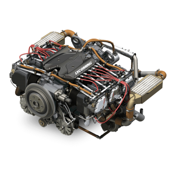
TEO-540-A1A Engine Installation and Operation Manual SYSTEM DESCRIPTION The Lycoming TEO-540-A1A Engine (Figure 1) is a direct-drive six-cylinder, horizontally opposed, turbocharged, electronically-controlled engine. It has electronic fuel injection, electronic ignition, electronic propeller governor control (an optional electronic propeller governor can be used), down exhaust, and induction air coolers. -
Page 24: Electronic Engine Control System (Eecs)
TEO-540-A1A Engine Installation and Operation Manual Electronic Engine Control System (EECS) The EECS is an electronic, microprocessor controlled system that continuously monitors and adjusts ignition timing, fuel injection timing, and fuel mixture based on operating conditions. The EECS eliminates the need for magnetos and manual fuel/air mixture. Figure 2 shows the EECS integrated controls. -
Page 25: Eecs Architecture
TEO-540-A1A Engine Installation and Operation Manual EECS Architecture The EECS architecture consists of: • Primary components (Figure 3): o Engine Control Unit (ECU) (also identified as ACU) - is a dual channel unit which contains system processors, input signal conditioning, output actuator drive stages, and aircraft communication interfaces. -
Page 26: Field Service Tool (Fst)
Field Service Tool (FST) The Field Service Tool (FST) is diagnostic software that identifies fault codes (Appendix C in the TEO-540-A1A Engine Maintenance Manual) and engine operation information to be used by ground-based support personnel to: • View fault codes from the ECU •... -
Page 27: Eecs Operation
TEO-540-A1A Engine Installation and Operation Manual EECS Operation The EECS does not have redundant actuators. It has only one fuel injector per cylinder, one exhaust bypass valve, and one propeller governor. Both channels (microprocessors) are capable of controlling the actuators but only one channel within the ECU can control the actuators at a given time - with the exception of the ignition coils, which are redundant with two per cylinder. -
Page 28: Electrical Interface
TEO-540-A1A Engine Installation and Operation Manual The Power Box supplies regulated, conditioned 13.8 VDC power through primary and secondary channels to the ECU, ignition coils, and warning annunciators. Each Power Box channel is identical and independent of the other and corresponds to the primary and secondary channels of the ECU. -
Page 29: Sensors
TEO-540-A1A Engine Installation and Operation Manual Sensors Sensors, identified in Table 2, are connected to the wiring harnesses. The sensors measure engine parameters and supply input to the ECU. The ECU uses this data to control operation of the engine through actuators. -
Page 30: Cylinders
TEO-540-A1A Engine Installation and Operation Manual Table 2 (Cont.) Sensors Sensor Name Abbr. Qty. Description Induction Manifold Air Measures induction air manifold pressure. Pressure Sensor Primary Compressor Inlet CIP-P Redundantly measures the pressure of the Pressure Sensor induction air entering the turbochargers. -
Page 31: Propeller Drive
AS127, Type 2. This direct drive propeller is attached to the crankshaft with six bolts. Oil is supplied through the propeller shaft for a single acting controllable pitch propeller. The engine must be approved by Lycoming for use with an FAR 23.1305 certified propeller system which is independent of the engine installation. -
Page 32: Electronic Ignition System
TEO-540-A1A Engine Installation and Operation Manual The engine fuel pump supplies the correct amount of fuel (through all operating ranges under all flight and atmospheric conditions) to the six fuel injectors. The ECU controls fuel injection. The ECU times and sets fuel injection sequentially and proportionally with the induction airflow. A fuel regulator adapter manifold assembly controls fuel pressure in the fuel rails connected to the fuel injectors. -
Page 33: Air Induction System
TEO-540-A1A Engine Installation and Operation Manual Air Induction System The Air Induction System is integral with the oil sump, with individual induction pipes going to each cylinder. Each passage in the induction system, where fuel and air mix, self-drain to prevent liquid lock in the cylinder. -
Page 34: Oil System Schematic
TEO-540-A1A Engine Installation and Operation Manual Figure 9 Oil System Schematic The oil pump is in the accessory housing. The wet sump-type Lubrication System supplies oil to the oil galleys in the crankcase and to the engine in all altitudes and atmospheric conditions. There are two drain plugs in the bottom of the oil sump, one on each side. -
Page 35: Engine Mounting
TEO-540-A1A Engine Installation and Operation Manual 2. Oil from the oil pump flows out through a threaded port on the accessory housing to a flexible line to the external oil cooler. 3. An oil cooler bypass valve in the engine accessory housing is installed to allow oil from the pump to bypass the oil cooler circuit. -
Page 36: Cylinder Number Designations
TEO-540-A1A Engine Installation and Operation Manual Cylinder Number Designations The propeller is at the front of the engine and the accessories are at the rear of the engine. Refer to Figure 10 for cylinder number designations. • Cylinders 1 and 2 are at the front of the engine. -
Page 37: Theory Of Operation
TEO-540-A1A Engine Installation and Operation Manual THEORY OF OPERATION EECS Operation The EECS: • Controls engine operation in accordance with Lycoming’s established engine operating specifications • Increases engine performance for: o More balanced distribution of power across each cylinder (balanced air-fuel mixture) -
Page 38: Engine Control Sequence
TEO-540-A1A Engine Installation and Operation Manual Engine Control Sequence NOTICE: The ignition switch is wired directly to both channels of the ACU. When the ignition switch is set to the ON position (open circuit) the ACU is enabled to supply fuel and spark to the engine. -
Page 39: Inoperative Cylinder Detection
TEO-540-A1A Engine Installation and Operation Manual Inoperative Cylinder Detection The EECS can identify a cylinder that is not in operation. As a result, the EECS disables all spark and fuel events for a cylinder that is non-operational. Cylinder Head Temperature Control The EECS monitors Cylinder Head Temperature (CHT) and corrects any cylinder temperature that has gone above the maximum temperature limit (shown in Appendix A). -
Page 40: Engine Overhaul Vs. Engine Rebuild
2. Engine rebuild - The engine is completely disassembled and assembled with parts and components that have been inspected to new limits. An engine rebuild is only completed at the Lycoming Engines’ factory. After an engine rebuild, the engine is issued a zero-time logbook. Timekeeping The EECS records the amount of time the controller has power (as "EECS Hours"). -
Page 41: Pilot Controls
TEO-540-A1A Engine Installation and Operation Manual PILOT CONTROLS AND ANNUNCIATORS Pilot Controls Table 1 identifies pilot controls for the TEO-540-A1A engine. Figure 1 shows typical cockpit controls. Table 1 Pilot Controls EECS aircraft breaker set to ON Airframe power is supplied to EECS... -
Page 42: Warning Indication Annunciators
NOTICE: During routine maintenance, such as a scheduled oil change, the service technician can display the ECU fault codes (Appendix D in the TEO-540-A1A Engine Maintenance Manual) using the FST on an attached laptop. If any fault is present, the service technician must take action to correct the fault. -
Page 43: Engine Reception And Lift
Uncrate Procedure for a New, Rebuilt, or Overhauled Engine 1. When the engine is received, make sure that the shipping container or box is not damaged. If the engine crate is damaged, speak to Lycoming Engines’ Service Department and the freight shipper. -
Page 44: Engine Preservative Oil Removal
TEO-540-A1A Engine Installation and Operation Manual 3. Examine the engine for damage or corrosion before lifting. If the engine is damaged or has corrosion, identify the areas of damage and corrosion. Speak to Lycoming Engines’ Service Department and the freight shipper. - Page 45 TEO-540-A1A Engine Installation and Operation Manual CAUTION MAKE SURE THE AREA IS CLEAR WHEN LIFTING THE ENGINE. DO NOT LIFT FROM THE FRONT, REAR, SIDES OR BOTTOM OF THE ENGINE. DO NOT LET THE ENGINE HIT ANY OBJECTS TO PREVENT DAMAGE TO THE ENGINE OR ITS COMPONENTS.
- Page 46 TEO-540-A1A Engine Installation and Operation Manual This page intentionally left blank. Engine Reception and Lift © 2018 Avco Corporation. All Rights Reserved Page 24 October 2018...
-
Page 47: Requirements For Engine Installation
TEO-540-A1A Engine Installation and Operation Manual REQUIREMENTS FOR ENGINE INSTALLATION Overview NOTICE: If a problem or leak is found on the engine, refer to the TEO-540-A1A Engine Maintenance Manual for corrective action. If the problem or leak continues, contact Lycoming Engines. - Page 48 A. Remove desiccant bags. B. During the procedure, if any of the dehydrator plugs (which contain crystals of silica gel) break and the crystals fall into the engine, complete the following per the TEO-540-A1A Engine Maintenance Manual: • Disassemble the affected portion of the engine.
-
Page 49: Plug In The Induction System
25 hours of operation during the oil change. E. Remove, examine, clean, and reinstall the oil suction screen per the “Oil Suction Screen Removal/Inspection/Cleaning/Installation” section in Chapter 12-10 of the TEO-540-A1A Engine Maintenance Manual. ™... - Page 50 05-30 of the TEO-540-A1A Engine Maintenance Manual. If the spark plugs are not acceptable, install new spark plugs with a new gasket. Refer to Chapter 74-20 in the TEO-540-A1A Engine Maintenance Manual for the spark plug removal, inspection, and installation procedures.
- Page 51 CAUTION IF PRESERVATIVE OIL TOUCHES PAINTED SURFACES, REMOVE THE OIL IMMEDIATELY TO PREVENT DAMAGE TO THE PAINT. NOTICE: To touch-up paint, refer to Chapter 72-10 in the TEO-540-A1A Engine Maintenance Manual. 8. Complete the preservative oil removal procedure as follows: A.
- Page 52 G. Safety wire/cable the oil sump drain plugs in accordance with the standard practices per the latest revision of AC43.13-1B or the latest revision of Service Instruction No. SI-1566. 12. Remove the oil filter and install a new oil filter. Refer to Chapter 12-10 in the TEO-540-A1A Engine Maintenance Manual.
-
Page 53: Step-2. Supply Interface Items
TEO-540-A1A Engine Installation and Operation Manual Step 2. Supply Interface Items For engine installation, the airframe manufacturer must supply the following items: Required for initial engine installation: • Correctly-sized hose for the fuel pump supply and fuel pump vent line •... -
Page 54: Step-3. Remove Components
“Engine Mount Inspection” section in Chapter 72-00 of the TEO-540-A1A Engine Maintenance Manual. The engine is installed in the aircraft using the rear top and bottom engine mounts. There are no mounts in the front of the engine. -
Page 55: Engine Installation
TEO-540-A1A Engine Installation and Operation Manual ENGINE INSTALLATION Engine Installation Overview NOTICE: All requirements identified in the chapter “Requirements for Engine Installation” must be completed before engine installation. To install the engine, refer to Table 1 and the section reference in this chapter for each step. -
Page 56: Step-1. Install The Ecu
NUMBERS DO NOT AGREE, DO NOT INSTALL THE ECU. CONTACT LYCOMING ENGINES IMMEDIATELY. Install the ECU with the correct serial number on the airframe in its designated location in accordance with the wiring diagram. Also refer to Appendix B in the TEO-540-A1A Engine Maintenance Manual for additional details. CAUTION... -
Page 57: Step-4. Connect The Wiring Harnesses
If a receptacle is damaged, repair or replace the receptacle as per the airframe manufacturer's instructions. 2. Appendix B of the TEO-540-A1A Engine Maintenance Manual identifies harness leads and plugs on the wiring harness. Examine the plugs on the engine wiring harness for damage. -
Page 58: Step 5. Connect The Power Control Linkage
If any part of a connector is damaged on the engine harness, replace the harness per instructions in the latest revision of the TEO-540-A1A Engine Maintenance Manual. If a connector is damaged on the engine airframe wiring harness, replace the harness per instructions in the latest revision of the Aircraft Maintenance Manual. -
Page 59: Step-6. Install External Accessories
Refer to the TEO-540-A1A Engine Maintenance Manual. Step 7. Install the Alternators 1. The alternators are supplied in kits. 2. In accordance with Chapter 72-70 in the TEO-540-A1A Engine Maintenance Manual: A. Install the two alternators. B. Install the alternator belts. -
Page 60: Step-10. Connect The Oil Hoses
TEO-540-A1A Engine Installation and Operation Manual NOTICE: Refer to Chapter 73-10 in the TEO-540-A1A Engine Maintenance Manual for suggested routing and configuration arrangement diagrams for fuel hoses on this engine. The fuel hose configuration diagram is for reference only. If specific fuel hose routing information is in airframe documentation, follow the airframe instruction. -
Page 61: Step-12. Install Components That Had Been Removed Before Engine Installation And Any Additional Ship Loose Components
Add ashless dispersant oil to turbocharged engines, as specified in Appendix A. Refer to Chapter 12- 10 in the TEO-540-A1A Engine Maintenance Manual for the procedure to add oil. NOTICE: To accurately calculate oil consumption, every time oil is added, record the quantity of oil added in the engine logbook. -
Page 62: Step-16. Engine Pre-Oil Procedure
6. Fill the oil cooler with oil per the airframe manufacturer’s instructions. 7. Remove one spark plug from each cylinder of the engine. Remove and discard the spark plug gasket per instructions in Chapter 74-20 in the TEO-540-A1A Engine Maintenance Manual. 8. Move the power control to the FULL OPEN position. -
Page 63: Step-17. Add Fuel
Up to six consecutive pre-oil start cycles can be done. Afterwards let the starter cool for 30 minutes. If stable oil pressure is not achieved, stop pre-oiling and contact Lycoming Engines. NOTICE: Unstable oil pressure or oil pressure less than 20 psi (138 kPa) could be an indication of obstructed or interrupted oil flow or air in the oil lines. -
Page 64: Engine Installation Checklist
TEO-540-A1A Engine Installation and Operation Manual Engine Installation Checklist Engine Installation Checklist Requirement Done Comment Make sure the engine is securely installed on the engine mounts. Make sure that the hardware that attaches the engine to the engine mounts is torqued as per the airframe manufacturer’s specified torque... -
Page 65: Field Run-In
Since a run-in is done on new, rebuilt or overhauled engines shipped from Lycoming Engines, the field run-in is not necessary. However, a field run-in procedure herein is done only on engines in the field after any of the following: •... - Page 66 O. After shutdown, examine the engine for oil and fuel leaks. Identify and correct the cause of any leaks. P. Per Chapter 12-10 in the TEO-540-A1A Engine Maintenance Manual: (1) Complete an oil change and replace the oil filter. Field Run-In ©...
- Page 67 TEO-540-A1A Engine Installation and Operation Manual (2) Remove, clean, and install the oil suction screen. (3) Add the correct grade and quantity of oil to the engine per the latest revision of Service Instruction No. SI-1014 and Appendix A of this manual.
- Page 68 TEO-540-A1A Engine Installation and Operation Manual This page intentionally left blank. Field Run-In © 2018 Avco Corporation. All Rights Reserved Page 46 October 2018...
-
Page 69: Engine Initiation
TEO-540-A1A Engine Installation and Operation Manual ENGINE INITIATION Engine Initiation Engine initiation includes the procedures in Table 1 which are to be done in the field on any of the following newly installed Lycoming engines: • Any new, overhauled, or rebuilt engine from the factory and field-overhauled engines •... - Page 70 TEO-540-A1A Engine Installation and Operation Manual Pre-Flight Inspection Checklist for Engine Initiation Engine Model Number TEO-540-A1A Engine Serial Number:___________________ Engine Time:______________________ Date Inspection Done:________________________ Inspection done by:___________________________ Requirement Comments Done Make sure that all switches are OFF or NORM. Make sure the NTO light or any other EECS light are not illuminated, which are an indication not to take-off.
- Page 71 TEO-540-A1A Engine Installation and Operation Manual Pre-Flight Inspection Checklist for Engine Initiation (Cont.) Examine the engine and cowl for indication of fuel and Identify and correct the cause of engine oil leaks. any leaks. Make sure that all baffles and baffle seals are installed in the correct position and are serviceable.
-
Page 72: Step 2. Pre-Start Inspection
3. Examine the engine for hydraulic lock which is a condition where fluid accumulates in the induction system or the cylinder assembly. Refer to Chapter 05-50 of the TEO-540-A1A Engine Maintenance Manual for details. WARNING DO NOT OPERATE A MALFUNCTIONING ENGINE. OPERATION OF A MALFUNCTIONING ENGINE CAN RESULT IN ADDITIONAL DAMAGE TO THE ENGINE, POSSIBLE BODILY INJURY OR DEATH. -
Page 73: Step 4. Operational Test
13. Monitor engine instrumentation for indicated oil pressure. If there is no oil pressure indication within 10 seconds, stop the engine. Contact Lycoming Engines. NOTICE: Unstable oil pressure or oil pressure less than 25 psi (172 kPa) could be an indication of obstructed or interrupted oil flow or air in the oil hose. - Page 74 TEO-540-A1A Engine Installation and Operation Manual CAUTION ON TURBOCHARGED ENGINES, OPERATE THE ENGINE AT LOW SPEED UNTIL THE OIL PRESSURE IS STABLE. OVERBOOST CAN OCCUR IF THE TURBOCHARGER CONTROL SYSTEM EXPERIENCES UNUSUAL OIL PRESSURES DUE TO AN OIL TEMPERATURE BELOW THE MINIMUM OPERATION TEMPERATURE OF 140ºF (60ºC).
-
Page 75: Step 5. Engine Run-Up
CONTACT LYCOMING ENGINES. NOTICE: After the first 25 hours of operation, change the oil. Examine the oil filter and oil suction screen. Refer to Chapter 12-10 in the TEO-540-A1A Engine Maintenance Manual. • Examine the air filters every other flight for dirt and be prepared to clean or replace them if necessary. -
Page 76: Step 6. Complete The Pre-Flight Test
TEO-540-A1A Engine Installation and Operation Manual 7. Decrease the power control back to 1200 rpm over 2 minutes. Allow the engine to stabilize and continue to operate. 8. Reset the EEC/ECU circuit breaker. Decrease the power control to IDLE and allow the engine to stabilize. - Page 77 TEO-540-A1A Engine Installation and Operation Manual A. The pre-flight test operates in the following sequence (with a calibrated delay between each test in the pre-flight test): (1) Exhaust bypass valve controls the manifold pressure (2) Propeller pitch will change if the electronic governor is installed.
- Page 78 • Excessive manifold pressure • NTO annunciator illuminated. NOTICE: If problems are found that go beyond field maintenance, contact Lycoming Engines. 9. The engine is ready for take-off when the oil temperature is greater than 140°F (60°C) and there are no faults or items that need corrective action.
-
Page 79: Step 7. Engine Stop
This data can be accessed after flight on the FST. 12. After 10 hours of engine operation for a new, overhauled, or rebuilt engine, complete the 10- hour inspection. Refer to the TEO-540-A1A Engine Maintenance Manual. Step 7. Engine Stop 1. -
Page 80: Step 8. Break-In/Flight Test/50-Hour Operation
During Break-In (50-Hour Operation)” must be completed any time new piston rings are installed or any time one or more cylinders are replaced per procedures in Chapter 72-30 in the TEO-540-A1A Engine Maintenance Manual. Engine break-in is done to seat the piston rings and stabilize oil consumption. Break-in includes two progressive procedures: •... -
Page 81: Step 9. Required Inspections During Break-In (50-Hour Operation)
Complete this flight test again, up to and including this step before releasing the aircraft for service. 12. Refer to the Chapter 12-10 of the TEO-540-A1A Series Engines Maintenance Manual to complete the “Oil Change Procedure” – drain the ashless dispersant oil and add new ashless dispersant oil up to the specified oil sump capacity in Appendix A. - Page 82 TEO-540-A1A Engine Installation and Operation Manual This page intentionally left blank. Engine Initiation © 2018 Avco Corporation. All Rights Reserved Page 60 October 2018...
-
Page 83: Step 1. Pre-Start Check
2. Examine the engine for hydraulic lock which is a condition where fluid accumulates in the induction system or the cylinder assembly. Refer to Chapter 05-50 of the TEO-540-A1A Engine Maintenance Manual for details. © 2018 Avco Corporation. All Rights Reserved... - Page 84 TEMPERATURE OR OIL PRESSURE IS NOT AT THE SPECIFIED MINIMUM LEVELS. 12. Monitor engine instrumentation for indicated oil pressure. If there is no oil pressure indication within 10 seconds, stop the engine. Contact Lycoming Engines. Engine Operation © 2018 Avco Corporation. All Rights Reserved...
-
Page 85: Step 3. Engine Run-Up
TEO-540-A1A Engine Installation and Operation Manual NOTICE: Unstable oil pressure or oil pressure less than 25 psi (172 kPa) could be an indication of obstructed or interrupted oil flow or air in the oil hose. In this case, stop, and have a technician look at the oil hoses. - Page 86 TEO-540-A1A Engine Installation and Operation Manual The PFT takes approximately 1 minute and allows the secondary channel to control each actuator. The EECS ensures the ignition, fuel, and turbocharger controls on each of the two channels are operating correctly. During this test, the EECS identifies any faults.
- Page 87 TEO-540-A1A Engine Installation and Operation Manual (7) All cylinders operate correctly when only the primary sparks are enabled and the fueling is set to a specified air-fuel ratio (8) All cylinders operate correctly when only the secondary spark is enabled and the fueling is set to a specified air-fuel ratio B.
- Page 88 • Excessive manifold pressure • NTO annunciator illuminated. NOTICE: If problems are found that go beyond field maintenance, contact Lycoming Engines’ Technical Support. 9. The engine is ready for take-off when the oil temperature is greater than 140°F (60°C) and there are no faults or items that need corrective action.
-
Page 89: Step 5. Engine Operation
NOTICE: After 25 hours of operation, change the oil. Examine the oil filter and screen. Refer to Chapter 12-10 in the TEO-540-A1A Engine Maintenance Manual. 3. Operation in Flight NOTICE: Although the EECS continuously monitors and adjusts ignition timing, fuel injection timing, and fuel mixture, and propeller governor setting based on operating conditions, continue to monitor engine functions during engine operation. -
Page 90: Step 6. Engine Stop
TEO-540-A1A Engine Installation and Operation Manual Step 6. Engine Stop 1. Before engine shutdown, operate the engine between 1000 and 1200 rpm for at least 5 minutes to allow turbocharger cool down. 2. When operating temperatures are stable and the EGT drops below 1100°F (593°C), increase engine speed to 1800 rpm for 15 to 20 seconds. -
Page 91: Faults
Fault Isolation - Use of Field Service Tools NOTICE: Do not use the Field Service Tool (FST) during flight. Refer to the Appendix C of the TEO-540-A1A Engine Maintenance Manual or the latest revision of SSP-118 for instructions to use the FST. - Page 92 TEO-540-A1A Engine Installation and Operation Manual Table 1 (Cont.) Action for Engine Conditions Engine Condition Explanation/Corrective Action Annunciators (Cont.) The NTO or TLO annunciator is Complete a safe landing and speak to Maintenance to illuminated but can still make isolate faults.
- Page 93 This setting was calculated by the airframe manufacturer and Lycoming for the most consistent operating points for take-off, climb, and cruise. © 2018 Avco Corporation. All Rights Reserved...
- Page 94 TEO-540-A1A Engine Installation and Operation Manual Table 1 (Cont.) Action for Engine Conditions Engine Condition Explanation/Corrective Action Engine Operation (Cont.) Manifold pressure decreases The EECS automatically prevents the turbocharger from during climb without moving the overspeed at high altitude by a set limit on the pressure power control ratio.
-
Page 95: Apply Heat To A Cold Engine
TEO-540-A1A Engine Installation and Operation Manual Table 1 (Cont.) Action for Engine Conditions Engine does not hold rpm during Complete a safe landing and speak to Maintenance. cruise, climb, or descent Fire Manually turn off engine fuel supply and complete a safe landing as quickly as possible. -
Page 96: Cold Weather Engine Start
8. Start the engine immediately after the hot air application. Also, refer to additional engine start information in the section “Cold Weather Engine Start”. Cold Weather Engine Start NOTICE: The following is Lycoming Engine’s recommended procedure for cold weather engine starts. Refer to the aircraft manufacturer’s POH for in-flight recommendations during cold weather. -
Page 97: Volcanic Ash
TEO-540-A1A Engine Installation and Operation Manual Volcanic Ash • Given the dynamic conditions of volcanic ash, Lycoming’s recommendation is NOT to operate the engine in areas where volcanic ash is present - in the air or on the ground. Refer to the latest revision of Service Instruction No. -
Page 98: Low Oil Pressure During Flight
• Refer to the latest revision of Service Bulletin No. SB-369 for corrective action for engine overspeed. • Record all incidents of engine overspeed in the engine logbook, along with the inspection and any specified corrective action taken per Chapter 05-50 in the TEO-540-A1A Engine Maintenance Manual. Low Oil Pressure During Flight Circumstances which cause loss of oil pressure are many and varied. -
Page 99: Engine Corrosion And Prevention
Because climate conditions are different in various geographic areas, Lycoming Engines only can give general recommendations for corrosion prevention. The owner and operator must take into... -
Page 100: Engine Preservation Guidelines - 31 To 60 Days
2. Stop the engine. 3. Refer to Chapter 12-10 in the TEO-540-A1A Engine Maintenance Manual to complete the following steps: A. Drain the lubricating oil from the sump or system and re-install the oil sump drain plugs. - Page 101 NOTICE: Cylinder dehydrator plugs are recommended to be installed in place of spark plugs because the dehydrator plugs provide moisture indication. 14. While the engine is still warm: A. Remove the intake pipes per instructions in Chapter 72-80 in the TEO-540-A1A Engine Maintenance Manual; remove the exhaust system per the airframe manufacturer’s manual.
-
Page 102: Extended Engine Preservation For 61 Days Or More
TEO-540-A1A Engine Installation and Operation Manual Extended Engine Preservation for 61 Days or More Refer to the latest revision of Service Instruction No. SI-1481. Fuel Injector Preservation Refer to the fuel injector manufacturer's instructions for preservation of fuel injectors. Engine Preservation and Storage ©... - Page 103 APPENDIX A Table A-1 contains engine specifications, Table A-2 identifies operating limits, and Table A-3 shows accessory drives for the TEO-540-A1A Series Engine. This appendix includes the following charts: • Cooling Air Requirements (Figure A-1) • Propeller Governor Oil Transfer Leakage Rate (Figure A-2) •...
- Page 104 * For possible alternative fuels, contact Technical Support at the phone numbers in the front of this manual. ** For optional starters and alternators, refer to the TEO-540-A1A Illustrated Parts Catalog or contact Lycoming Engines. NOTICE: All locations and rotations are as viewed from the accessory housing end (back) of the engine unless specified differently.
- Page 105 TEO-540-A1A Engine Installation and Operation Manual Table A-2 (Cont.) Table of Operating Limits for Engine Fuel Pressure to Engine Drive Pump (relative to ambient Maximum 65 psig 448 kPa air pressure) Minimum -2 psig -14 kPa Fuel Rail Pressure (relative to manifold pressure)
- Page 106 TEO-540-A1A Engine Installation and Operation Manual Table A-3 Accessory Drives Maximum Torque Maximum Overhang Direction of Drive Accessory Type of Drive Continuous Static Moment Rotation Ratio in.-lb in.-lb in.-lb Starter Counter- 16.556:1 clockwise Alternators (2) SAE Clockwise 3.80:1 Accessory Counter- AND20000* 1.3:1...
- Page 107 TEO-540-A1A Engine Installation and Operation Manual Figure A-1 Cooling Air Requirements © 2018 Avco Corporation. All Rights Reserved Appendix A October 2018 Page 85...
-
Page 108: A-2 Propeller Governor Oil Transfer Leakage Rate
TEO-540-A1A Engine Installation and Operation Manual Figure A-2 Propeller Governor Oil Transfer Leakage Rate Appendix A © 2018 Avco Corporation. All Rights Reserved Page 86 October 2018... -
Page 109: A-3 Sonic Nozzle Air Flow
TEO-540-A1A Engine Installation and Operation Manual Figure A-3 Sonic Nozzle Airflow © 2018 Avco Corporation. All Rights Reserved Appendix A October 2018 Page 87... -
Page 110: A-4 2500 Rpm Sea Level And Altitude Performance
TEO-540-A1A Engine Installation and Operation Manual Figure A-4 2500 RPM Sea Level and Altitude Performance Appendix A © 2018 Avco Corporation. All Rights Reserved Page 88 October 2018... -
Page 111: A-5 2400 Rpm Sea Level And Altitude Performance
TEO-540-A1A Engine Installation and Operation Manual Figure A-5 2400 RPM Sea Level and Altitude Performance © 2018 Avco Corporation. All Rights Reserved Appendix A October 2018 Page 89... -
Page 112: A-6 2200 Rpm Sea Level And Altitude Performance
TEO-540-A1A Engine Installation and Operation Manual Figure A-6 2200 RPM Sea Level and Altitude Performance Appendix A © 2018 Avco Corporation. All Rights Reserved Page 90 October 2018... -
Page 113: A-7 Fuel Flow Versus Percent Of Rated Power
TEO-540-A1A Engine Installation and Operation Manual Figure A-7 Fuel Flow versus Percent of Rated Power © 2018 Avco Corporation. All Rights Reserved Appendix A October 2018 Page 91... - Page 114 TEO-540-A1A Engine Installation and Operation Manual This page intentionally left blank. Appendix A © 2018 Avco Corporation. All Rights Reserved Page 92 October 2018...
-
Page 115: Appendix B Operating Limitations
TEO-540-A1A Engine Installation and Operation Manual APPENDIX B OPERATING LIMITATIONS Functional Limitation Requirements Limitations of the EECS EEC Physical Environmental Limits The EECS components (ECU, Power Box, and ADL (Data Logger)) have the physical environmental limits shown in Table B-1. - Page 116 TEO-540-A1A Engine Installation and Operation Manual This page intentionally left blank. Appendix B © 2018 Avco Corporation. All Rights Reserved Page 94 October 2018...
-
Page 117: Appendix C Safety
Safety Alert Messages Ref. ID Title WARNING Connection of equipment or devices other than the Lycoming “Field Service Tool” to CAN 2 Bus may compromise safe EECS operation. Connection of non-Lycoming approved equipment or devices to the CAN 2 bus interface is prohibited. The Field Service Tool must not be used in flight. - Page 118 TEO-540-A1A Engine Installation and Operation Manual This page intentionally left blank. Appendix C © 2018 Avco Corporation. All Rights Reserved Page 96 October 2018...
-
Page 119: Appendix D Wiring Diagrams
NOTICE: For Wiring Harness Leads and Connection Location, Air Frame Wiring Interface, Communications Buses, Volt Power System Connection, System Wiring Diagrams, and Communications Bus Data refer to Appendix B in the TEO-540-A1A Engine Maintenance Manual. © 2018 Avco Corporation. All Rights Reserved... - Page 120 TEO-540-A1A Engine Installation and Operation Manual This page intentionally left blank. Appendix D © 2018 Avco Corporation. All Rights Reserved Page 98 October 2018...
Need help?
Do you have a question about the TEO-540-A1A and is the answer not in the manual?
Questions and answers