
Related Manuals for Lycoming IO-390-D Series


Summary of Contents for Lycoming IO-390-D Series
- Page 1 Engine Maintenance Manual (Principal Manual) IO-390-D Series March 2020 Part No. MM-IO-390-D Series © 2020 Avco Corporation. All Rights Reserved.
- Page 2 Visit us Online: www.lycoming.com NOTE: Lycoming recommends that owners of this manual sign up for email notification on the Technical Publications page of our website https://www.lycoming.com/contact/knowledge-base/publications. By submitting your email address, you will receive notification whenever Lycoming publishes a new...
-
Page 3: Airworthiness Limitations
"Fuel Line Inspection" procedure in Chapter 73-10 of this manual. 3. Mandatory Inspection - Exhaust Valve and Guide At every 1000 hours of operation for IO-390-D Series engines, examine the exhaust valve and guide conditions. Refer to the section "Exhaust Valve and Guide Inspection" in Chapter 72-30. - Page 4 IO-390-D Series Engine Maintenance Manual IO-390-D Series Engine Maintenance Manual This page intentionally left blank Airworthiness Limitations © 2020 Avco Corporation. All Rights Reserved Page ii March 2020...
-
Page 5: Record Of Revisions
IO-390-D Series Engine Maintenance Manual IO-390-D Series Engine Maintenance Manual RECORD OF REVISIONS Revision Revised Revision Date Revision Description Original Release of Maintenance Manual – Original Part No. MM-IO-390-D Series © 2020 Avco Corporation. All Rights Reserved Record of Revisions... - Page 6 IO-390-D Series Engine Maintenance Manual IO-390-D Series Engine Maintenance Manual This page intentionally left blank. Record of Revisions © 2020 Avco Corporation. All Rights Reserved Page iv March 2020...
-
Page 7: Service Document List
IO-390-D Series Engine Maintenance Manual IO-390-D Series Engine Maintenance Manual SERVICE DOCUMENT LIST NOTICE: The following is a list of service documents referenced in or incorporated into the information in this manual. Always refer to the latest revision of any service document (including any supplements) for changes or additional information. - Page 8 IO-390-D Series Engine Maintenance Manual IO-390-D Series Engine Maintenance Manual SERVICE DOCUMENT LIST (CONT.) Incorporation Number Subject Date S.I. 1014 03/20 Lubricating Oil Recommendations S.I. 1029 03/20 Tightening Procedures for Crankcase Thru-Studs and Bolts S.I. 1037 03/20 Approved Pistons, Rings and Cylinders for Use on Lycoming Aircraft Engines S.I.
- Page 9 Engine Inspection in Particulate-Laden Environments Counterweight and Roller Removal, Inspection, and S.I. 1535 03/20 Installation S.I. 1566 03/20 Lycoming Engines Approves the Use of Safety Cable Installation of Lycoming Electronic Ignition System S.I. 1569 03/20 (EIS) S.I. 1575 03/20 New Connecting Rod Bushing S.L.
- Page 10 IO-390-D Series Engine Maintenance Manual IO-390-D Series Engine Maintenance Manual This page intentionally left blank. Service Document List © 2020 Avco Corporation. All Rights Reserved Page viii March 2020...
-
Page 11: Table Of Contents
25-Hour Engine Inspection for IO-390-D Series Engines ............17 — 50-Hour Engine Inspection for IO-390-D Series Engines ............20 — 100-Hour or Annual Engine Inspection for IO-390-D Series Engines ........23 — 400-Hour Engine Inspection for IO-390-D Series Engines ............ 28 —... - Page 12 ................ 05-50 — Lightning Strike - After a Lightning Strike ................47 — Engine Overspeed ........................47 —Table 1 - Overspeed Values for IO-390-D Series Engines ..........48 — Incorrect Fuel or Fuel Contamination ..................50 — Soaked Engine......................... 51 —...
- Page 13 Metal Contamination of the Lubrication System ..............56 — Propeller Strike, Sudden Engine Stoppage or Loss of a Propeller Blade Tip ......56 —Engine Inspection Checklist After Propeller Strike for IO-390-D Series Engines ..... 56 — Cleaning Methods for Non-Destructive Testing ..............64 Servicing - Replenishing ....................
- Page 14 Engine Mount Inspection ...................... 105 — Return to Service Procedure ....................106 Engine Disassembly....................... 72-05 — Table 1 - Sequence of IO-390-D Series Engine Disassembly Procedures ...... 107 Engine Assembly ......................72-10 — Corrosion Prevention ......................113 — Painting the Engine and Engine Components ...............
- Page 15 IO-390-D Series Engine Maintenance Manual IO-390-D Series Engine Maintenance Manual Subject Page Crankcase Maintenance (Cont.) .................. 72-20 — Crankcase Dimensional Inspection ..................138 — Crankshaft Inspection ......................140 — Alignment Dowel Inspection ....................149 — Crankshaft Bearing Surface Inspection ................. 150 —...
- Page 16 IO-390-D Series Engine Maintenance Manual IO-390-D Series Engine Maintenance Manual Subject Page Accessory Housing Maintenance ................. 72-25 — Accessory Housing Removal ....................185 — Oil Pump Removal ........................ 186 — Oil Pump Installation ......................186 — Fuel Pump Plunger Removal ....................
- Page 17 IO-390-D Series Engine Maintenance Manual IO-390-D Series Engine Maintenance Manual Subject Page Lubrication System Maintenance ................72-50 — Oil Pressure Adjustment ....................... 231 — Oil System Inspection ......................231 — Oil Line Inspection........................ 231 — Oil Line Replacement ......................232 —...
- Page 18 IO-390-D Series Engine Maintenance Manual IO-390-D Series Engine Maintenance Manual Subject Page Electrical System Maintenance (Cont.) ............... 72-70 — Alternator Belt Replacement ....................247 — Starter Replacement ......................247 — Starter Ring Gear Support Replacement ................248 — Starter Ring Gear Replacement .....................
- Page 19 IO-390-D Series Engine Maintenance Manual IO-390-D Series Engine Maintenance Manual Subject Page Ignition System Maintenance (Cont.)................74-20 — Ignition Harness Removal ..................... 276 — Ignition Harness Inspection ....................276 — Ignition Harness Installation ....................277 Electronic Ignition System / Magneto Maintenance ..........
- Page 20 IO-390-D Series Engine Maintenance Manual IO-390-D Series Engine Maintenance Manual This page intentionally left blank. Table of Contents © 2020 Avco Corporation. All Rights Reserved Page xviii March 2020...
-
Page 21: Abbreviations And Acronyms
IO-390-D Series Engine Maintenance Manual IO-390-D Series Engine Maintenance Manual ABBREVIATIONS AND ACRONYMS Airframe Manufacturer’s Manual Air Transport Association Celsius Centimeter Exhaust Gas Temperature Electronic Ignition System Fahrenheit Federal Aviation Administration Federal Aviation (and Space) Regulation ft.-lb Foot Pound (torque) - Page 22 IO-390-D Series Engine Maintenance Manual IO-390-D Series Engine Maintenance Manual ABBREVIATIONS AND ACRONYMS (CONT.) Outer / Outside Diameter Original Equipment Manufacturer Ounce Painted Internal Diameter Parts Manufacturer Approval Part Number Pilot’s Operating Handbook Pounds per square inch Revolutions per Minute...
-
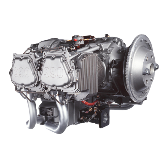
Page 23: Introduction
IO-390-D Series Engine Maintenance Manual INTRODUCTION The Lycoming IO-390-D series engines are direct-drive four-cylinder, horizontally opposed, fuel- injected, air-cooled engines. Each engine has tuned induction and a down exhaust. There are different IO-390-D engine models. Figures 1 and 2 show the IO-390-D engine models. - Page 24 MANUAL UNLESS OTHERWISE SPECIFIED. PROCEDURES IN THIS MANUAL MUST BE DONE BY QUALIFIED PERSONNEL WITH THE REQUISITE CERTIFICATIONS. Before you do maintenance on the IO-390-D series engine, read this manual in its entirety. Obey all procedures and inspections in this manual. Introduction ©...
- Page 25 NOTICE: If you do not obey the maintenance procedures in this manual for this engine, you can void the engine warranty. Refer to your warranty for details. Refer to the IO-390-D Series Engine Installation and Operation Manual for engine description, uncrating procedures, acceptance check, engine lift procedure, engine preservation and storage,...
- Page 26 List of Publications Refer to the latest revision of Service Letter No. L114 for a list of Lycoming Engines' publications. Environmental Compliance Lycoming Engines recommends that engine owners and engine service personnel be in compliance with all federal, state, and local environmental regulations when solvents, paint, fuel, oil, chemicals, or other consumables are used in engine service.
-
Page 27: Required Maintenance
(break-in/flight test), fuels and oil to be used, and operating specifications are included in the IO-390-D Series Engine Installation and Operation Manual. List of Tools for Service and Maintenance Table 1 identifies tools used for service and maintenance. -
Page 28: Time Between Overhaul (Tbo)
Time Between Overhaul (TBO) Refer to the latest revision of Service Instruction No. SI-1009 for any changes or special circumstances for the recommended TBO. Lycoming Engines recommends engines be sent to the factory for overhaul. 05-00 © 2020 Avco Corporation. All Rights Reserved... -
Page 29: Safety Precautions - Before Engine Maintenance
IO-390-D Series Engine Maintenance Manual IO-390-D Series Engine Maintenance Manual Safety Precautions - Before Engine Maintenance WARNING BEFORE THE START OF ANY SERVICE OR MAINTENANCE ON AN INSTALLED ENGINE OR AN ENGINE ON A TEST STAND CONNECTED TO POWER, ENSURE THE IGNITION SWITCH IS TURNED OFF AND DISABLE/DISCONNECT ALL POWER TO THE ENGINE TO PREVENT ACCIDENTAL ENGINE START-UP. - Page 30 IO-390-D Series Engine Maintenance Manual IO-390-D Series Engine Maintenance Manual The cotter pin head must install as a snug fit into the castellation of the nut. Unless otherwise specified, bend one end of the cotter pin back over the stud or bolt and the other end flat against the nut.
-
Page 31: General Engine Inspection Criteria
RELATED TO THE INSTALLATION OF PMA PARTS COULD VOID THE WARRANTY. Lycoming Engines recommends these engines be assembled, maintained, and overhauled using only genuine Lycoming parts. (PMA parts have not been approved for use by Lycoming Engines.) Refer to the applicable parts catalog for genuine Lycoming parts. - Page 32 IO-390-D Series Engine Maintenance Manual IO-390-D Series Engine Maintenance Manual This page intentionally left blank. 05-00 © 2020 Avco Corporation. All Rights Reserved Page 6 March 2020...
-
Page 33: Time Limits / Service Checks
IO-390-D Series Engine Maintenance Manual 05-10 - TIME LIMITS / SERVICE CHECKS Engine Inspection Schedule for IO-390-D Series Engines As shown in the Engine Inspection Schedule below, the scope of engine inspections includes visual observations during engine servicing or maintenance as well as inspections based on progressive time intervals after the engine is put into service. - Page 34 IO-390-D Series Engine Maintenance Manual IO-390-D Series Engine Maintenance Manual This page intentionally left blank. 05-10 © 2020 Avco Corporation. All Rights Reserved Page 8 March 2020...
-
Page 35: Required Engine Inspections For Io-390-D Series Engines
IO-390-D Series Engine Maintenance Manual 05-20 - REQUIRED ENGINE INSPECTIONS FOR IO-390-D SERIES ENGINES NOTICE: Except as noted, in this chapter the term “magneto” can refer to either the Lycoming Electronic Ignition System (EIS) or optional, traditional magnetos, depending on the type of system installed on the engine. - Page 36 IO-390-D Series Engine Maintenance Manual IO-390-D Series Engine Maintenance Manual Visual Inspection Checklist for IO-390-D Series Engines Engine Model Number___________________ Engine Serial Number:___________________ Engine Time:___________________________ Date Inspection Done:____________________ Inspection done by:______________________________ Findings/ Item Comments Done Corrective Action Engine Compartment Look for and remove unwanted dirt, dust, sand, or particles on the engine and in its compartment.
- Page 37 IO-390-D Series Engine Maintenance Manual IO-390-D Series Engine Maintenance Manual Visual Inspection Checklist for IO-390-D Series Engines (Cont.) Findings/ Item Comments Done Corrective Action Lubrication System NOTICE: On new, rebuilt, or overhauled engines, during the first 50 hours of engine operation, operate this engine on mineral oil until oil consumption has stabilized.
- Page 38 IO-390-D Series Engine Maintenance Manual IO-390-D Series Engine Maintenance Manual Visual Inspection Checklist for IO-390-D Series Engines (Cont.) Cylinders - Refer to figures in Chapter 72-30. Item to Examine Cyl. 1 Cyl. 2 Cyl. 3 Cyl. 4 NOTICE: During the first hours of service, engines can have some leakage at the cylinder base or the cylinder base studs.
- Page 39 IO-390-D Series Engine Maintenance Manual IO-390-D Series Engine Maintenance Manual Visual Inspection Checklist for IO-390-D Series Engines (Cont.) Findings/ Item Comments Done Corrective Action Crankcase Examine the external surface of the Replace a damaged or crankcase for damage, cracks. cracked crankcase.
- Page 40 (5) Start the engine and run-up per instructions in the IO-390-D Series Engine Installation and Operation Manual. (6) Operate the engine for 3 minutes on the ground (per the IO-390-D Series Engine Installation and Operation Manual). Complete a leak check while the engine is in operation.
-
Page 41: Operational Leak Check Sheet For Io-390-D Series Engines
IO-390-D Series Engine Maintenance Manual IO-390-D Series Engine Maintenance Manual Operational Leak Check Sheet for IO-390-D Series Engines Engine Model Number___________________ Engine Serial Number:___________________ Engine Time:___________________________ Date Inspection Done:____________________ Inspection done by:______________________________ Findings/ Item Comments Done Corrective Action Examine the cowling, engine and... -
Page 42: 10-Hour Initial Engine Inspection For Io-390-D Series Engines
Complete this inspection after the first 10 hours of initial operation of a new, rebuilt, or overhauled engine. Copy and complete the 10-Hour Initial Engine Inspection Checklist for IO-390-D Series engines as a record of engine service. Record the engine hours. -
Page 43: 25-Hour Engine Inspection For Io-390-D Series Engines
• If the rate of oil consumption has not stabilized NOTICE: Refer to the “Oil Servicing Schedule” in Chapter 12-10. B. Copy and complete the 25-hour Engine Inspection Checklist for IO-390-D Series engines as a record of engine service. Record the engine hours. - Page 44 IO-390-D Series Engine Maintenance Manual IO-390-D Series Engine Maintenance Manual 25-Hour Engine Inspection Checklist for IO-390-D Series Engines (Cont.) Inspection Item Comments Results/Notes Done WARNING EXAMINE THE OIL PRESSURE SCREEN OR THE FILTER ELEMENT OF THE OIL FILTER FOR UNWANTED METAL PARTICLES. CLEAN THE OIL PRESSURE SCREEN.
- Page 45 Correct any problem before Ground Check in Chapter 72-00. flight to make sure the engine operates correctly to specifications*. * Appendix A of the IO-390-D Series Engine Installation and Operation Manual. © 2020 Avco Corporation. All Rights Reserved 05-20 March 2020 Page 19...
-
Page 46: 50-Hour Engine Inspection For Io-390-D Series Engines
A. Complete the 50-Hour Engine Inspection after every 50 hours of engine operation or every 4 months (whichever occurs first). B. Copy and complete the 50-hour Engine Inspection Checklist for IO-390-D Series Engines as a record of engine service. Record the engine hours. - Page 47 IO-390-D Series Engine Maintenance Manual IO-390-D Series Engine Maintenance Manual 50-Hour Engine Inspection Checklist for IO-390-D Series Engines (Cont.) Inspection Item Comments Results/Notes Done Remove, examine, clean and If blockage is found, record install the oil suction screen at the and identify the blockage oil sump.
- Page 48 IO-390-D Series Engine Maintenance Manual IO-390-D Series Engine Maintenance Manual 50-Hour Engine Inspection Checklist for IO-390-D Series Engines (Cont.) Inspection Item Comments Results/Notes Done Induction System Refer to the “Induction Complete the Induction System System Inspection” Inspection. procedure in Chapter 72-80.
-
Page 49: 100-Hour Or Annual Engine Inspection For Io-390-D Series Engines
100 hours of operation or during each annual aircraft inspection (whichever occurs first). B. Copy and complete the 100-hour or Annual Engine Inspection Checklist for IO-390-D Series engines as a record of engine service. Record the engine hours. - Page 50 IO-390-D Series Engine Maintenance Manual IO-390-D Series Engine Maintenance Manual 100-Hour or Annual Engine Inspection Checklist for IO-390-D Series Engines (Cont.) Inspection Item Comments Results/Notes Done EIS (Cont.) Inspect ignition harness connection to EIS. If Back-Up Battery System is installed, ensure it is being maintained or inspected in accordance with its ICA.
- Page 51 IO-390-D Series Engine Maintenance Manual IO-390-D Series Engine Maintenance Manual 100-Hour or Annual Engine Inspection Checklist for IO-390-D Series Engines (Cont.) Inspection Item Comments Results/Notes Done Fuel System Complete the Fuel System Refer to the section "Fuel System Inspection” procedure in Inspection.
- Page 52 IO-390-D Series Engine Maintenance Manual IO-390-D Series Engine Maintenance Manual 100-Hour or Annual Engine Inspection Checklist for IO-390-D Series Engines (Cont.) Inspection Item Comments Results/Notes Done Fuel System (Cont.) Examine solder joints at the end Replace cracked fuel lines.* of fuel lines for cracks.
- Page 53 IO-390-D Series Engine Maintenance Manual IO-390-D Series Engine Maintenance Manual 100-Hour or Annual Engine Inspection Checklist for IO-390-D Series Engines (Cont.) Cylinder Compression Check Complete the “Cylinder Compression Check Procedure” in Chapter 72-30. Record the results for each cylinder. Cylinder 1...
-
Page 54: 400-Hour Engine Inspection For Io-390-D Series Engines
A. Complete the 400-Hour Engine Inspection after every 400 hours of operation since the engine has been in service. B. Copy and complete the 400-Hour Engine Inspection Checklist for IO-390-D Series Engines as a record of engine service. Record the engine hours. - Page 55 IO-390-D Series Engine Maintenance Manual IO-390-D Series Engine Maintenance Manual 400-Hour Engine Inspection Checklist for IO-390-D Series Engines (Cont.) Complete the “Cylinder Borescope Inspection” procedure in Chapter 72-30. Record the results below for each engine cylinder. Cylinder 1 Cylinder 2...
-
Page 56: 500-Hour Engine Inspection For Io-390-D Series Engines
A. Complete the 500-Hour Engine Inspection after every 500 hours of operation since the engine has been in service. B. Copy and complete the 500-Hour Engine Inspection Checklist for IO-390-D Series Engines as a record of engine service. Record the engine hours. -
Page 57: 1000-Hour Engine Inspection For Io-390-D Series Engines
If this 1000-hour inspection is completed prior to the scheduled 1000-hour inspection it must be completed 1000 hours from the time of inspection. B. Copy and complete the 1000-Hour Engine Inspection Checklist for IO-390-D Series Engines as a record of engine service. Record the engine hours. - Page 58 IO-390-D Series Engine Maintenance Manual IO-390-D Series Engine Maintenance Manual This page intentionally left blank. 05-20 © 2020 Avco Corporation. All Rights Reserved Page 32 March 2020...
-
Page 59: Cleaning
HANDLING OF CLEANING MATERIALS AND THE USE OF PERSONAL PROTECTIVE EQUIPMENT. NOTICE: IO-390-D Series engines can be equipped with aluminum or magnesium oil sump or accessory housing. Be aware of the type of components installed on your engine before cleaning, completing maintenance, or replacing parts. - Page 60 IO-390-D Series Engine Maintenance Manual IO-390-D Series Engine Maintenance Manual Table 1 Cleaning Guidelines for Engine Components Component or Part Cleaning Agent* Guidelines Refer to the “Crankshaft Cleaning” Crankshaft Mineral spirits, MIL-PRF- 680 or equivalent procedure in this chapter Refer to the “Crankshaft Counterbore...
- Page 61 IO-390-D Series Engine Maintenance Manual IO-390-D Series Engine Maintenance Manual Table 1 (Cont.) Cleaning Guidelines for Engine Components Component or Part Cleaning Agent* Guidelines Refer to the “Piston Cleaning” procedure Piston Mineral spirits (MIL-PRF- 680), Safety Solvent or in this chapter.
-
Page 62: Crankshaft Cleaning
IO-390-D Series Engine Maintenance Manual IO-390-D Series Engine Maintenance Manual Table 1 (Cont.) Cleaning Guidelines for Engine Components Component or Part Cleaning Agent* Guidelines Refer to the “Injection Nozzle Cleaning” ® Precision fuel injector Hoppes No. 9 Gun nozzles Cleaning Solvent and section in this chapter. -
Page 63: Crankshaft Gear Cleaning
IO-390-D Series Engine Maintenance Manual IO-390-D Series Engine Maintenance Manual B. Dry the crankshaft counterbore threads with compressed air. Figure 1 Threads in the Crankshaft Counterbore C. Clean the threads of the crankshaft counterbore (Figure 1) as follows: (1) Use the correct sized undamaged bottoming tap for a 5/16-24 thread size. -
Page 64: Tappet Cleaning
IO-390-D Series Engine Maintenance Manual IO-390-D Series Engine Maintenance Manual 5. Tappet Cleaning A. Clean the tappets using the cleaning procedure in the next steps. Refer to the latest revision of Service Instructions SI-1011 and SI-1514 for details about tappets. -
Page 65: Soft Carbon Removal
IO-390-D Series Engine Maintenance Manual IO-390-D Series Engine Maintenance Manual A. Grit-Blast Media CAUTION DO NOT USE SAND OR METALLICALLY ABRASIVE MATERIALS TO GRIT-BLAST. During grit-blasting, for general cleaning of components not subject to Non-Destructive Testing (NDT), only use mildly abrasive blast media such as 17-grit walnut shells or equivalent. -
Page 66: Hard Carbon Removal
ALUMINUM PARTS. NOTICE: If you are not sure if the component is steel or contains magnesium, contact Technical Support at Lycoming Engines at the phone numbers in the front of the manual. CAUTION DO NOT USE WIRE BRUSHES OR METAL SCRAPERS ON BEARINGS OR CONTACT SURFACES. -
Page 67: Piston Cleaning
IO-390-D Series Engine Maintenance Manual IO-390-D Series Engine Maintenance Manual F. Grit-Blasting the Combustion Chamber in an Engine Cylinder: (1) Remove the intake and exhaust valves from the cylinder to be cleaned. Refer to Chapter 72-30. (2) Remove the spark plugs from the cylinder. Refer to the section “Spark Plug Removal” in Chapter 74-20. -
Page 68: Steel, Aluminum, Or Magnesium Parts Cleaning
IO-390-D Series Engine Maintenance Manual IO-390-D Series Engine Maintenance Manual NOTICE: There are slightly different cleaning procedures for Precision and AVStar injection nozzles. Refer to the applicable procedure to clean your injection nozzles. Clean the Precision fuel injection nozzle with: Clean the AVStar fuel injection nozzle with: •... -
Page 69: Spark Plug Cleaning
IO-390-D Series Engine Maintenance Manual NOTICE: If you are not sure if the component is steel or contains magnesium or aluminum, contact Technical Support at Lycoming Engines at the phone numbers in the front of this manual. A. Put the component fully immersed in mineral spirits or equivalent in a bath tank. -
Page 70: Cleaning Guidelines For A Soaked Engine
IO-390-D Series Engine Maintenance Manual IO-390-D Series Engine Maintenance Manual B. To remove volcanic ash: (1) Wear personal protective equipment (gloves, respiratory, and eye protection). (2) Per the aircraft manufacturer’s instructions, thoroughly remove the ash or particulate from the aircraft by hand brushing or air/vacuuming. Make sure that all ash is removed from the engine and cowling. - Page 71 IO-390-D Series Engine Maintenance Manual IO-390-D Series Engine Maintenance Manual B. Use any of the following cleaning methods as long as it is not harmful to the component or its intended function: • Vapor degreasing • Solvent degreasing • Ultrasonic cleaning •...
- Page 72 IO-390-D Series Engine Maintenance Manual IO-390-D Series Engine Maintenance Manual This page intentionally left blank. 05-30 © 2020 Avco Corporation. All Rights Reserved Page 46 March 2020...
-
Page 73: Unscheduled Corrective Maintenance
(in accordance with the airframe and propeller manufacturer’s recommended procedures/guidance). If there is evidence of arc damage, send the engine either to Lycoming Engines or an FAA authorized repair facility for an internal inspection and evaluation on whether an engine repair or overhaul is necessary. - Page 74 IO-390-D Series Engine Maintenance Manual IO-390-D Series Engine Maintenance Manual NOTICE: Refer to the engine specifications in Appendix A of the IO-390-D Series Engine Installation and Operation Manual for rated engine speed. All incidents of engine overspeed must be recorded in the engine logbook along with any corrective action identified herein.
- Page 75 IO-390-D Series Engine Maintenance Manual IO-390-D Series Engine Maintenance Manual (3) Cylinder Overspeed Inspection (a) Complete the cylinder compression check on all cylinders as a check for the sealing quality of the rings and valves. Refer to the section “Cylinder Compression Check Procedure”...
-
Page 76: Incorrect Fuel Or Fuel Contamination
IO-390-D Series Engine Maintenance Manual C. Incorrect Fuel or Fuel Contamination (1) Refer to Appendix A in the IO-390-D Series Engine Installation and Operation Manual or the latest revision of Service Instruction No. SI-1070 for approved fuels, octane ratings, and the use of a higher grade fuel for this engine. -
Page 77: Soaked Engine
NOTICE: The composition of the substance that the engine has been exposed to can affect the type and extent of the damage. It is recommended the engine be sent to Lycoming Engines for evaluation. Include a description of the liquid in which the engine was soaked. -
Page 78: Engine On Fire Or Near A Fire
Replace any components exposed to a fire or heat from a fire. It is recommended an engine exposed to a fire or the heat from a fire be sent to Lycoming Engines for evaluation. Include a description that the engine was in or near a fire or external heat. -
Page 79: Hydraulic Lock
• Failure to remove preservative oil from an engine that had been in storage. (5) It is recommended an engine suspected of having hydraulic lock be sent to Lycoming Engines for evaluation. Include a description and details of the hydraulic lock. - Page 80 IO-390-D Series Engine Maintenance Manual IO-390-D Series Engine Maintenance Manual Table 2 Action to Take in Volcanic Ash Conditions Maintenance after flight… Maintenance after 10 hours of operation or the next flight… Wear personal protective equipment (gloves, respiratory, Wear personal protective equipment. Examine the and eye protection).
-
Page 81: Valve Sticking
Unless there is an adequate quantity of lubricating oil at all times during flight, loss of oil pressure can occur. NOTICE: Refer to Appendix A of the IO-390-D Series Engine Installation and Operation Manual for the minimum oil quantity. -
Page 82: Metal Contamination Of The Lubrication System
(e) Examine the oil pump for malfunction. Replace the oil pump if it is not operating correctly. Refer to Chapter 72-25. (f) If the oil pressure indication system is operating correctly and there has been confirmation that oil pressure loss/oil starvation has occurred, contact Lycoming Engines’ Technical Support. J. Metal Contamination of the Lubrication System (1) If metallic particles/residue, metal shavings or metal flakes is found in the engine oil after oil servicing, refer to the “Identification of Metallic Solids After Oil Servicing”... - Page 83 Lycoming Engines can only recommend BEFORE FURTHER FLIGHT, that you complete the tasks in the sequential order shown in the Engine Inspection Checklist After Propeller Strike for IO-390-D Series Engines (in this chapter) as corrective action for a propeller strike. Make a copy of the checklist and complete it.
- Page 84 IO-390-D Series Engine Maintenance Manual IO-390-D Series Engine Maintenance Manual Engine Inspection Checklist After Propeller Strike for IO-390-D Series Engines Engine Model Number: Engine Serial Number: Date Inspection Started: Date Inspection Completed: Corrective Action Sequential Task Additional Information Done/Comments Examine the propeller for extent of Condition of Propeller/Corrective damage;...
- Page 85 IO-390-D Series Engine Maintenance Manual IO-390-D Series Engine Maintenance Manual Engine Inspection Checklist After Propeller Strike for IO-390-D Series Engines (Cont.) Corrective Action Sequential Task Additional Information Done/Comments Complete grit-blast cleaning* of Make sure there is no dirt, debris, the accessory housing with fine sludge, paint, or any other abrasive (150-grit or finer).
- Page 86 IO-390-D Series Engine Maintenance Manual IO-390-D Series Engine Maintenance Manual Engine Inspection Checklist After Propeller Strike for IO-390-D Series Engines (Cont.) Corrective Action Sequential Task Additional Information Done/Comments CAUTION BASED UPON ACCUMULATED ENGINEERING, TECHNICAL, HISTORICAL DATA AVAILABLE, LYCOMING ENGINES PROHIBITS STRAIGHTENING OR GRINDING OF BENT CRANKSHAFT PROPELLER FLANGES TO RESTORE MAXIMUM RUN-OUT SPECIFICATION.
- Page 87 IO-390-D Series Engine Maintenance Manual IO-390-D Series Engine Maintenance Manual Engine Inspection Checklist After Propeller Strike for IO-390-D Series Engines (Cont.) Corrective Action Sequential Task Additional Information Done/Comments Refer to the “Connecting 18. Complete a check of the Parallelism Measurement Rod/Parallelism/Squareness Check”...
- Page 88 IO-390-D Series Engine Maintenance Manual IO-390-D Series Engine Maintenance Manual Engine Inspection Checklist After Propeller Strike for IO-390-D Series Engines (Cont.) Additional Corrective Action Sequential Task Information Done/Comments 25. Complete a magnetic particle inspection† on Record test the following internal parts made of steel: results.
- Page 89 IO-390-D Series Engine Maintenance Manual IO-390-D Series Engine Maintenance Manual Engine Inspection Checklist After Propeller Strike for IO-390-D Series Engines (Cont.) Additional Corrective Action Sequential Task Information Done/Comments 35. Replace all of the roller tappets with new or Refer to Chapter serviceable roller tappets.
-
Page 90: Cleaning Methods For Non-Destructive Testing
C. Requirements for NDT Personnel Personnel who complete the Magnetic Particle and Fluorescent Penetrant Inspections on Lycoming engine components must be qualified and certified to a written procedure in accordance with NAS-410, Certification and Qualification of NDT personnel. Also, personnel who make the "accept"... -
Page 91: Servicing - Replenishing
(4) Look at the oil level indication on the dipstick end. NOTICE: The approved oil, oil sump capacity, and the minimum quantity for engine operation are identified in Appendix A of the IO-390-D Series Engine Installation and Operation Manual. (5) If the oil level is not sufficient, add the correct oil through the fill port. Refer to the section “Add Oil to the Engine”... -
Page 92: Oil Consumption
4. Oil Type and Viscosity A. The oils to be used in the IO-390-D Series engine are identified in Appendix A of the IO- 390-D Series Engine Installation and Operation Manual. B. Refer to the latest revision of Service Instruction No. SI-1014 for additional details. -
Page 93: Oil Leak Check
IO-390-D Series Engine Maintenance Manual IO-390-D Series Engine Maintenance Manual Measure the oil level per the “Oil Level Check” procedure in this chapter. Add more oil if necessary until the oil level in the engine is sufficient. Install the oil level gage assembly (dipstick) into the oil level gage tube securely. -
Page 94: Oil Change Procedure
On new, rebuilt, or overhauled engines, during the first 50 hours of engine operation, operate this engine on mineral oil until oil consumption has stabilized. Per the “Engine Operation” chapter in the IO-390-D Series Engine Installation and Operation Manual, operate the engine until the oil temperature stabilizes and then shut down the engine wait at least 15 minutes after engine shutdown and then proceed with the oil change. -
Page 95: Engine Pre-Oil Procedure
IO-390-D Series Engine Maintenance Manual IO-390-D Series Engine Maintenance Manual CAUTION MAKE SURE THAT THE OIL SUMP DRAIN PLUG IS INSTALLED TIGHTLY. IF THE DRAIN PLUG IS NOT TIGHTLY INSTALLED AND LEAKS, ENGINE FAILURE CAN OCCUR. C. Send the oil sample in the vial to the same laboratory (that has been used in the past) for spectrographical analysis to compare past results and identify a wear trend pattern. - Page 96 H. If oil pressure of at least 20 psi (138 kPa) was sustained in the previous step, repeat the pre- oil start cycle to make sure oil pressure holds stable and that there is not a sudden drop in oil pressure. If oil pressure is not stable or drops suddenly, stop pre-oiling and contact Lycoming Engines.
-
Page 97: Oil Suction Screen Removal/Inspection/Cleaning/Installation
IO-390-D Series Engine Maintenance Manual IO-390-D Series Engine Maintenance Manual 10. Oil Suction Screen Removal/Inspection/Cleaning/Installation NOTICE: On the IO-390-D (Figure 2) engines there is an oil suction screen in the oil sump. A. Remove and discard the safety wire/cable from the oil drain plug and the screen plug on the oil sump (Figure 2). -
Page 98: Oil Pressure Screen Removal/Inspection/Cleaning/Installation
IO-390-D Series Engine Maintenance Manual IO-390-D Series Engine Maintenance Manual 11. Oil Pressure Screen Removal/Inspection/Cleaning/Installati NOTICE: Complete this procedure after every 25 hours of engine operation. A. Drain the oil from the oil sump per “Oil Change Procedure” in this chapter. -
Page 99: Oil Filter Replacement
IO-390-D Series Engine Maintenance Manual IO-390-D Series Engine Maintenance Manual 12. Oil Filter Replacement After the initial 25-hour oil filter replacement and oil change, if oil consumption is stabilized, replace the oil filter after every 50 hours of engine operation during an oil change, unless otherwise directed. -
Page 100: Identification Of Metallic Solids After Oil Servicing
NOTICE: For spectrometric oil analysis to be an effective diagnostic tool, Lycoming Engines recommends that oil samples must be taken and analyzed at each oil change. Contact Lycoming Engines’ Technical Support at the phone numbers at the front of this manual, • The cause of the metal contamination cannot be found •... - Page 101 IO-390-D Series Engine Maintenance Manual IO-390-D Series Engine Maintenance Manual The visual inspection procedure is slightly different for oil filter elements and screens: Visual inspection for oil filter element: Visual inspection for oil pressure screen and oil suction screen: Remove the oil filter element from the oil filter Drain all fluid oil through a strainer cloth or canister.
- Page 102 IO-390-D Series Engine Maintenance Manual IO-390-D Series Engine Maintenance Manual NOTICE: Table 2 only applies to engines that use genuine Lycoming Parts. Table 2 Guidelines for Identification of Metal Particulates and Chips & Corrective Action Metals/ Possible Source of Origin Tests &...
- Page 103 IO-390-D Series Engine Maintenance Manual IO-390-D Series Engine Maintenance Manual Table 2 (Continued) Guidelines for Identification of Metal Particulates and Chips & Corrective Action Metals/ Possible Source of Origin Tests & Characteristics Next Step Alloys on Lycoming Engine If lead chips, chunks,...
- Page 104 IO-390-D Series Engine Maintenance Manual IO-390-D Series Engine Maintenance Manual Table 3 Guidelines for Particle Quantity and Size on Oil Filter or Oil Suction Screen Corrective Action Condition (Table 4) Continue to operate the 1 to 9 pieces of metal (1/16 in. (1.2 mm)) diameter or less)
- Page 105 If the cause of the metal contamination cannot be identified, speak with the Lycoming Engines Technical Support, phone number at the front of this manual. If there is unusual aluminum, bronze, or iron contamination in the oil, make sure you have a full...
-
Page 106: Recommended Corrective Action Options
Chapter 72-30. Complete the “Engine Removal” procedure in Chapter 72-00 and send the engine to Lycoming Engines or an authorized repair facility for customized evaluation. Complete the “Engine Disassembly” procedure in Chapter 72-05 and examine engine components per the applicable chapters in this manual to identify and correct the cause. -
Page 107: Oil Contamination Check
17. Oil Contamination Check NOTICE: Lycoming engine models that have a propeller governor can have a small screen molded within the propeller governor gasket. Remove this gasket and look for particle contamination on the propeller gasket screen. Replace with a new propeller governor gasket. - Page 108 IO-390-D Series Engine Maintenance Manual IO-390-D Series Engine Maintenance Manual This page intentionally left blank. 12-10 © 2020 Avco Corporation. All Rights Reserved Page 82 March 2020...
-
Page 109: Fault Isolation
B. The "Ref." column in Table 1 contains references to the following: (1) A numeric entry such as "72-00" refers to a chapter in this manual. (2) IOM refers to the IO-390-D Series Engine Installation and Operation Manual. (3) AMM refers to the Airframe Manufacturer’s Manual. - Page 110 IO-390-D Series Engine Maintenance Manual IO-390-D Series Engine Maintenance Manual Table 1 (Cont.) Fault Isolation Guide Problem Cause Corrective Action Ref. Engine will not start Fault in the ignition 1. Visually examine the harness for or starts with system physical damage.
- Page 111 IO-390-D Series Engine Maintenance Manual IO-390-D Series Engine Maintenance Manual Table 1 (Cont.) Fault Isolation Guide Problem Cause Corrective Action Ref. Refer to the “EIS Troubleshooting Rough Idle (Cont.) Lycoming Electronic Ignition System (EIS) Guide” in this chapter. 1. Complete the “Cylinder Compression Low cylinder Check Procedure.”...
- Page 112 “Fuel Pump Replacement” procedure.* 1. Complete the “Fuel Manifold Valve sticking in fuel Removal” procedure. manifold 2. Send to either Lycoming Engines or an authorized overhaul facility for 73-10 evaluation. 3. Complete the “Fuel Manifold Installation” procedure. Engine will not idle Lean idle mixture 1.
- Page 113 2. Replace a damaged fuel flow gage. 1. Complete the “Fuel Manifold Fuel manifold does not Removal” procedure.* open all the way at times. 2. Send to Lycoming Engines or an 73-10 authorized repair facility. 3. Complete the “Fuel Manifold Installation” procedure.
- Page 114 IO-390-D Series Engine Maintenance Manual IO-390-D Series Engine Maintenance Manual Table 1 (Cont.) Fault Isolation Guide Problem Cause Corrective Action Ref. Low fuel flow Fuel line to fuel flow Look for fuel dye stains to identify (Cont.) gage is broken, loose, or...
- Page 115 IO-390-D Series Engine Maintenance Manual IO-390-D Series Engine Maintenance Manual Table 1 (Cont.) Fault Isolation Guide Problem Cause Corrective Action Ref. Engine will not turn Too much air dropped 1. Put the aircraft in a dust-free area. static rpm or will not through a new air filter 2.
- Page 116 IO-390-D Series Engine Maintenance Manual IO-390-D Series Engine Maintenance Manual Table 1 (Cont.) Fault Isolation Guide Problem Cause Corrective Action Ref. Engine will not turn Incorrect EIS-to-engine Refer to the EIS Troubleshooting static rpm or will not timing Guide in this chapter.
- Page 117 IO-390-D Series Engine Maintenance Manual IO-390-D Series Engine Maintenance Manual Table 1 (Cont.) Fault Isolation Guide Problem Cause Corrective Action Ref. Engine surges (Cont.) Low engine oil level Complete a check of the oil level. Add oil. Refer to the sections "Oil Level 12-10 Check"...
- Page 118 IO-390-D Series Engine Maintenance Manual IO-390-D Series Engine Maintenance Manual Table 1 (Cont.) Fault Isolation Guide Problem Cause Corrective Action Ref. Low oil pressure Pressure relief valve is Turn the adjusting screw (on the oil (Cont.) out of adjustment pressure relief valve) to adjust oil...
- Page 119 IO-390-D Series Engine Maintenance Manual IO-390-D Series Engine Maintenance Manual Table 1 (Cont.) Fault Isolation Guide Problem Cause Corrective Action Ref. Low oil pressure Failed or failing Drain the oil from the oil sump. 12-10 (Cont.) bearings Open the crankcase and examine the 72-05 bearings.
- Page 120 IO-390-D Series Engine Maintenance Manual IO-390-D Series Engine Maintenance Manual Table 1 (Cont.) Fault Isolation Guide Problem Cause Corrective Action Ref. Excessive oil Worn valve guides 1. Measure the valve guides for wear consumption as per instructions in the section “Exhaust Valve and Guide...
- Page 121 IO-390-D Series Engine Maintenance Manual IO-390-D Series Engine Maintenance Manual Table 1 (Cont.) Fault Isolation Guide Problem Cause Corrective Action Ref. High oil Oil cooler bypass valve Replace the oil cooler bypass valve. temperature (Cont.) 72-50 is not operating correctly or seating...
- Page 122 IO-390-D Series Engine Maintenance Manual IO-390-D Series Engine Maintenance Manual Table 1 (Cont.) Fault Isolation Guide Problem Cause Corrective Action Ref. High oil pressure Relocated oil pressure Use only the approved oil pressure take-off point on the take-off point. engine...
- Page 123 IO-390-D Series Engine Maintenance Manual IO-390-D Series Engine Maintenance Manual Table 2 provides troubleshooting guidelines for applicable EIS. Table 2 EIS Troubleshooting Guide Problem Problem Isolation Probable Cause Corrective Action Engine runs Ignition Verify ignition Engine baffling Internal ignition fault...
- Page 124 IO-390-D Series Engine Maintenance Manual IO-390-D Series Engine Maintenance Manual Table 2 EIS Troubleshooting Guide Problem Problem Isolation Probable Cause Corrective Action Unable to Unable to verify #1 cylinder @ TDC #1 cylinder not @ TDC Verify location of engine #1 cylinder.
- Page 125 IO-390-D Series Engine Maintenance Manual IO-390-D Series Engine Maintenance Manual Problem Problem Isolation Probable Cause Corrective Action Engine runs Isolate EIS Unable to verify ignition correctly timed to Ignition not timed to Reinstall ignition unit in accordance with rough (Cont.)
- Page 126 IO-390-D Series Engine Maintenance Manual IO-390-D Series Engine Maintenance Manual This page intentionally left blank. 12-30 © 2020 Avco Corporation. All Rights Reserved Page 100 March 2020...
-
Page 127: Engine Removal And Return To Service
(8) Drain oil from engine. Refer to the “Oil Change Procedure” in Chapter 12-10. (9) Remove accessories. (10) If the engine is to be stored, complete the engine preservation procedure before engine removal. Refer to instructions in the IO-390-D Series Engine Installation and Operation Manual. 2. Engine Removal Procedure A. - Page 128 IO-390-D Series Engine Maintenance Manual IO-390-D Series Engine Maintenance Manual E. Apply a cap over oil and fuel lines and connections to prevent spillage and debris from entering the engine. F. Apply tags to identify ports, clips, tubes, wires, etc. for reference to make correct connections during engine installation.
-
Page 129: Engine Installation Preparation Requirements
Table 1 to prepare the engine for installation (if the engine was not in storage). If the engine was in storage, refer to the IO-390-D Series Engine Installation & Operation Manual for instructions to prepare an engine that has been in storage. -
Page 130: Operational Ground Check
4. Operational Ground Check NOTICE: The purpose of this check is to make sure the installed engine operates in the aircraft according to specifications in Appendix A of the IO-390-D Series Engine Installation and Operation Manual. Per the component manufacturer's instructions, calibrate the cylinder head temperature gage, oil temperature gage, oil pressure gage, manifold pressure gage, and tachometer prior to testing. -
Page 131: Engine Mount Inspection
IO-390-D Series Engine Maintenance Manual IO-390-D Series Engine Maintenance Manual To adjust the idling speed to the desired rpm: When the idle speed is stable, move the cockpit mixture control lever with a very slow, steady pull toward the IDLE CUT-OFF position, do not let the engine stop. While monitoring the tachometer, steadily move the mixture control lever to the FULL RICH position. -
Page 132: Return To Service Procedure
IO-390-D Series Engine Maintenance Manual IO-390-D Series Engine Maintenance Manual 7. Return to Service Procedure Before returning this engine to service; • Make sure that you correct all problems and complete all of the necessary maintenance. • Complete the “Operational Ground Check” in this chapter. -
Page 133: Engine Disassembly
12-10, and the engine is removed from the airframe (per instructions in this manual and the applicable Airframe Maintenance Manual). NOTICE: In this chapter the term “magneto” can refer to either the Lycoming Electronic Ignition System (EIS) or optional, traditional magnetos, depending on the type of system installed on the engine. - Page 134 IO-390-D Series Engine Maintenance Manual IO-390-D Series Engine Maintenance Manual Table 1 (Cont.) Sequence of IO-390-D Series Engine Disassembly Procedures Step Reference Step Reference “Alternator and Bracket Removal” and Step 5 Step 8 Procedures in Chapter 73-10 • Fuel Line Removal “Alternator Belt Removal”...
- Page 135 IO-390-D Series Engine Maintenance Manual IO-390-D Series Engine Maintenance Manual Table 1 (Cont.) Sequence of Engine Disassembly Procedures Step Reference Step Reference “Oil Pump Removal” and “Fuel Pump Step 11 Procedures in Chapters 12-10 and 72- Step 14 Plunger Removal” procedures in...
- Page 136 IO-390-D Series Engine Maintenance Manual IO-390-D Series Engine Maintenance Manual Table 1 (Cont.) Sequence of Engine Disassembly Procedures Step Reference Step Reference “Intercylinder Baffle Removal” “Piston Removal” procedure in Chapter Step 17 Step 20 procedure in Chapter 72-30 72-30 Remove the...
- Page 137 IO-390-D Series Engine Maintenance Manual IO-390-D Series Engine Maintenance Manual Table 1 (Cont.) Sequence of Engine Disassembly Procedures Step Reference Step Reference “Crankcase Disassembly” procedure in “Oil Plug Removal” procedure in Step 23 Step 26 Chapter 72-20 Chapter 72-20 Separate the...
- Page 138 IO-390-D Series Engine Maintenance Manual IO-390-D Series Engine Maintenance Manual This page intentionally left blank. 72-05 © 2020 Avco Corporation. All Rights Reserved Page 112 March 2020...
-
Page 139: Engine Assembly
2. Painting the Engine and Engine Components Lycoming Engines recommends that the basic engine be painted as an assembly (without accessories, intake tubes, fluid lines, wiring harness). However, if it is necessary to paint an individual component: •... - Page 140 IO-390-D Series Engine Maintenance Manual IO-390-D Series Engine Maintenance Manual Table 1 (Cont.) Paint Stripping and Painting Guidelines for Components Magnesium Parts (1) Clean all traces of oil and grease from the part using a neutral, non- corrosive, degreasing medium followed by a rinse.
-
Page 141: Limits And Clearances
IO-390-D Series Engine Maintenance Manual IO-390-D Series Engine Maintenance Manual Table 1 (Cont.) Paint Stripping and Painting Guidelines for Components (5) Use a cloth dipped in paint thinner to remove paint from all surfaces where Cylinder (Cont.) it could have accidentally accumulated. -
Page 142: Engine Assembly Procedure
A. Complete the sequence of steps in Table 2. B. Complete the Engine Assembly Checklist in the chapter. NOTICE: In this chapter the term “magneto” can refer to either the Lycoming Electronic Ignition System (EIS) or optional, traditional magnetos, depending on the type of system installed on the engine. - Page 143 IO-390-D Series Engine Maintenance Manual IO-390-D Series Engine Maintenance Manual Table 2 (Cont.) Sequence of Engine Assembly Procedures Step Reference Step Reference “Crankshaft Idler Gear Shaft “Tappet Assembly Installation” Step 7 Step 10 Installation” procedure in Chapter 72- procedure in Chapter 72-20...
- Page 144 IO-390-D Series Engine Maintenance Manual IO-390-D Series Engine Maintenance Manual Table 2 (Cont.) Sequence of Engine Assembly Procedures Step Reference Step Reference “Camshaft Assembly and Installation” “Crankshaft Oil Seal Installation” Step 13 Step 16 procedure in Chapter 72-20 procedure in Chapter 72-20...
- Page 145 IO-390-D Series Engine Maintenance Manual IO-390-D Series Engine Maintenance Manual Table 2 (Cont.) Sequence of Engine Assembly Procedures Step Reference Step Reference “Cylinder Installation” section in Chapters 12-10, 72-25, 72-50, and 73- Step 19 Step 22 10 in this manual and airframe...
- Page 146 IO-390-D Series Engine Maintenance Manual IO-390-D Series Engine Maintenance Manual Table 2 (Cont.) Sequence of Engine Assembly Procedures Step Reference Step Reference “Oil Level Gage Tube and Assembly “Spark Plug Gap Setting” and “Spark Step 25 Step 28 Installation” procedure in Chapter 72- Plug Installation”...
- Page 147 IO-390-D Series Engine Maintenance Manual IO-390-D Series Engine Maintenance Manual Table 2 (Cont.) Sequence of Engine Assembly Procedures Step Reference Step Reference “Propeller Governor Oil Line “Fuel Line Installation” procedure in Step 31 Step 35 Installation” procedure in Chapter 72-50...
-
Page 148: Engine Assembly Checklist
IO-390-D Series Engine Maintenance Manual IO-390-D Series Engine Maintenance Manual Engine Assembly Checklist The Engine Assembly Checklist for IO-390-D Series Engines is a guide and a record of completion for engine assembly. Engine Assembly Checklist for IO-390-D Series Engines Engine Model Number__________________ Engine Serial Number:__________________... - Page 149 IO-390-D Series Engine Maintenance Manual IO-390-D Series Engine Maintenance Manual Engine Assembly Checklist for IO-390-D Series Engines (Cont.) Item Comments Done Install counterweights on the crankshaft per the “Counterweight Installation” procedure in Chapter 72-20. Start with a clean crankcase which passed the “Crankcase Inspection Before Disassembly”...
- Page 150 IO-390-D Series Engine Maintenance Manual IO-390-D Series Engine Maintenance Manual Engine Assembly Checklist for IO-390-D Series Engines (Cont.) Item Comments Done Complete the “Crankshaft Installation” procedure in Chapter 72-20. Measure the thrust face clearances between the *Measurement: crankshaft and crankcase per the “Crankshaft Installation”...
- Page 151 IO-390-D Series Engine Maintenance Manual IO-390-D Series Engine Maintenance Manual Engine Assembly Checklist for IO-390-D Series Engines (Cont.) Item Comments Done Complete the “Oil Sump Installation” procedure in Chapter 72-50. Be sure to install a new oil sump gasket. Complete the “Piston Installation” procedure in Chapter 72-30 for all four pistons.
- Page 152 IO-390-D Series Engine Maintenance Manual IO-390-D Series Engine Maintenance Manual Engine Assembly Checklist for IO-390-D Series Engines (Cont.) Item Comments Done Complete the “Injection Nozzle Installation” procedure in Chapter 73-10. Install new fuel lines and complete the “Fuel Line Installation” procedure in Chapter 73-10.
-
Page 153: Propeller Flange Bushing Replacement
IO-390-D Series Engine Maintenance Manual IO-390-D Series Engine Maintenance Manual 72-15- PROPELLER FLANGE BUSHING REPLACEMENT 1. Propeller Flange Bushing Removal NOTICE: Designated bushings are installed in specified locations on the propeller in a specific indexed configuration. A. During removal of the bushings from the propeller flange (also known as the crankshaft flange), attach a removable non-adhesive label/tag on the bushing that identifies the correct bushing part number and location for reference on reassembly. - Page 154 IO-390-D Series Engine Maintenance Manual IO-390-D Series Engine Maintenance Manual This page intentionally left blank. 72-15 © 2020 Avco Corporation. All Rights Reserved Page 128 March 2020...
-
Page 155: Crankcase Maintenance
D. Examine the crankcase breather for cracks, dents, and damage. If cracks, dents or damage are found, remove the engine as per Chapter 72-00 and send to Lycoming Engines. E. Examine the ends of the breather tube for scoring and out of roundness. If scoring or out-of-... -
Page 156: Crankcase Disassembly
IO-390-D Series Engine Maintenance Manual IO-390-D Series Engine Maintenance Manual 3. Crankcase Disassembly Put the crankcase upright on a suitable work surface Crankshaft Idler Gear and Bushing Removal (1) Remove the idler gears and bushings (Figure 2) from the idler gear shafts. -
Page 157: Tappet, Main Bearing And O-Ring Removal
IO-390-D Series Engine Maintenance Manual IO-390-D Series Engine Maintenance Manual Remove the camshaft when the crankcase halves are separated enough to allow for removal (Figure 7). Remove the camshaft tachometer shaft, spacer, pin, and internal retaining ring. Discard the internal retaining ring, spacer, and pin. - Page 158 IO-390-D Series Engine Maintenance Manual IO-390-D Series Engine Maintenance Manual (3) Push the hollow end of the Tappet Assembly Tool over the hydraulic tappet plunger and withdraw the plunger. (4) Bend a right angle in one end of a piece of wire and insert this end into the space between the plunger assembly and the tappet body.
-
Page 159: Propeller Governor Drive Removal/Disassembly (Engines With Front-Mounted Propeller Governor Drives)
IO-390-D Series Engine Maintenance Manual IO-390-D Series Engine Maintenance Manual Propeller Governor Drive Removal/Disassembly (Engines with Front-Mounted Propeller Governor Drives) (1) If not already done, remove the four nuts, lock washers and washers (Figure 13) from the front-mounted propeller governor or the propeller governor drive cover. Discard the lock washers. -
Page 160: Oil Plug Removal
IO-390-D Series Engine Maintenance Manual IO-390-D Series Engine Maintenance Manual Oil Plug Removal Remove the threaded NPT plugs from the accessory housing, oil sump, and crankcase to facilitate cleaning (Figures 14, 15, and 16). Figure 14 Figure 15 Oil Plugs in the Accessory Housing... -
Page 161: Piston Cooling Nozzle Removal
IO-390-D Series Engine Maintenance Manual IO-390-D Series Engine Maintenance Manual Piston Cooling Nozzle Removal Remove the four piston cooling oil nozzles from the crankcase (Figure 19). Figure 19 Piston Cooling Nozzles 4. Crankshaft Disassembly WARNING USE CARE WHEN HANDLING THE CRANKSHAFT AND ITS PARTS – DO NOT ETCH OR MAKE MARKS ON THE CRANKSHAFT OR COUNTERWEIGHTS. -
Page 162: Counterweight Removal
IO-390-D Series Engine Maintenance Manual IO-390-D Series Engine Maintenance Manual NOTICE: Skip the next step if a constant speed propeller is used because an expansion plug is not installed in the crankshaft. CAUTION DO NOT DRILL THE EXPANSION PLUG OR USE A MAGNET TO REMOVE THE PLUG OR ANY LITTLE PIECES OF PLUG REMNANTS. - Page 163 IO-390-D Series Engine Maintenance Manual IO-390-D Series Engine Maintenance Manual NOTICE: Since every counterweight has a matched pair of rollers that must stay with each counterweight, make another non-adhesive label to identify the roller pair that goes with each counterweight. Apply the label to the roller pair during removal to prevent mixing the roller pairs on different counterweights during reassembly.
-
Page 164: Crankcase Dimensional Inspection
IO-390-D Series Engine Maintenance Manual IO-390-D Series Engine Maintenance Manual (c) Use the Arbor Press Spindle and Counterweight Bushing Driver ST-92 to press both bushings out from one side of the counterweight. Refer to Figure 23. (d) Turn the counterweight over. - Page 165 IO-390-D Series Engine Maintenance Manual IO-390-D Series Engine Maintenance Manual Crankcase Dimensional Inspection Checklist for IO-390-D Series Engines Engine Model Number__________________ Engine Serial Number:__________________ Engine Time:______________________ Date Inspection Done: _____________________ Inspection done by:______________________________ Findings/ Item Comments Done Corrective Action Measure the I.D. of the...
-
Page 166: Crankshaft Inspection
C. Continue with the crankshaft inspection. Do not make scores, scratches, or etch markings of any kind on the crankshaft. A mark in any of these areas can cause the crankshaft to weaken and to possibly fail. Crankshaft Inspection Checklist for IO-390-D Series Engines Engine Model Number__________________ Engine Serial Number:__________________ Engine Time:______________________... - Page 167 IO-390-D Series Engine Maintenance Manual IO-390-D Series Engine Maintenance Manual Crankshaft Inspection Checklist for IO-390-D Series Engines (Cont.) Findings/ Item Comments Done Corrective Action Figure 24 Area to be Examined Refer to the “Crankshaft Bearing Examine the crankshaft Surface Inspection” section in this bearing surfaces.
- Page 168 IO-390-D Series Engine Maintenance Manual IO-390-D Series Engine Maintenance Manual Crankshaft Inspection Checklist for IO-390-D Series Engines (Cont.) CAUTION LYCOMING ENGINES NO LONGER APPROVES STRAIGHTENING OR GRINDING OF BENT CRANKSHAFT FLANGES TO RESTORE MAXIMUM RUN-OUT. IF THE CRANKSHAFT FLANGE IS BENT, REPLACE THE CRANKSHAFT.
- Page 169 IO-390-D Series Engine Maintenance Manual IO-390-D Series Engine Maintenance Manual Crankshaft Inspection Checklist for IO-390-D Series Engines (Cont.) Crankshaft Gear Inspection NOTICE: Any time the crankshaft gear bolt (Figure 27) and lockplate are removed from the crankshaft gear, the bolt and lockplate are to be discarded and replaced with a new bolt and new lockplate for the applicable crankshaft gear.
- Page 170 IO-390-D Series Engine Maintenance Manual IO-390-D Series Engine Maintenance Manual Crankshaft Inspection Checklist for IO-390-D Series Engines (Cont.) Findings/ Item Comments Done Corrective Action Crankshaft Gear Inspection (Cont.) Measure the diameter of the If the diameter of the pilot flange pilot flange of the crankshaft is less than 2.125 in.
- Page 171 Corrective Action Criteria for Crankshaft Gear Replacement Lycoming Engines no longer approves rework or repair of an unacceptable crankshaft gear. Replace the crankshaft gear with a serviceable crankshaft gear if any of the following are found during the crankshaft gear identification and inspection.
- Page 172 IO-390-D Series Engine Maintenance Manual IO-390-D Series Engine Maintenance Manual Crankshaft Inspection Checklist for IO-390-D Series Engines (Cont.) Findings/ Item Comments Done Corrective Action Examine the gear mounting If the mounting face of the face of the crankshaft crankshaft counterbore is counterbore.
- Page 173 IO-390-D Series Engine Maintenance Manual IO-390-D Series Engine Maintenance Manual Crankshaft Inspection Checklist for IO-390-D Series Engines (Cont.) Findings/ Item Comments Done Corrective Action Counterweight Inspection (Cont.) Examine the surface of the Replace the counterweight Outcome of Counterweight counterweight for scoring,...
- Page 174 IO-390-D Series Engine Maintenance Manual IO-390-D Series Engine Maintenance Manual Crankshaft Inspection Checklist for IO-390-D Series Engines (Cont.) Findings/ Item Comments Done Corrective Action Counterweight Inspection (Cont.) Examine the surface of the If the roller surface is not Outcome of Roller Pair...
-
Page 175: Alignment Dowel Inspection
IO-390-D Series Engine Maintenance Manual IO-390-D Series Engine Maintenance Manual Results of Fluorescent Penetrant Inspection of Crankshaft Crankshaft P/N Inspector Crankshaft S/N Date of Inspection Black Light Inspection of Crankshaft Bore (inner diameter) Guidelines and Inspection Item Findings and Action Taken... -
Page 176: Crankshaft Bearing Surface Inspection
IO-390-D Series Engine Maintenance Manual IO-390-D Series Engine Maintenance Manual E. Measure the diameter of the alignment dowel (Dimension A) shown in Figure 32 and determine if the measurement conforms to the values for the different alignment dowel part numbers in the latest revision of Service Bulletin No. SB-475 for additional details. -
Page 177: Camshaft Inspection
If a hydraulic tappet body has been rejected for spalling, carefully examine the corresponding camshaft lobe for evidence of distress, surface irregularity, or feathering on the edges. Camshaft Inspection Checklist for IO-390-D Series Engines Findings/ Item Comments Done Corrective Action Camshaft Visual Inspection Visually examine all surfaces of the camshaft (Figure 33) –... -
Page 178: Connecting Rod Inspection
10. Connecting Rod Inspection Copy the Connecting Rod Inspection Checklist to record the condition of all of the connecting rods and any corrective action. Connecting Rod Inspection Checklist for IO-390-D Series Engines Engine Model Number___________________ Engine Serial Number:___________________ Engine Time:_______________________ Date Inspection Done:_______________________ Inspection done by:______________________________ Disassemble the connecting rod;... - Page 179 IO-390-D Series Engine Maintenance Manual IO-390-D Series Engine Maintenance Manual Connecting Rod Inspection Checklist for IO-390-D Series Engines (Cont.) Item Comments Findings/Corrective Action Done Bushing ID Measurement Measure the Inner If the connecting rod bushing Diameter (ID) of is worn beyond service limits...
-
Page 180: Connecting Rod Bushing Replacement
IO-390-D Series Engine Maintenance Manual IO-390-D Series Engine Maintenance Manual Connecting Rod Inspection Checklist for IO-390-D Series Engines (Cont.) Connecting Rod Bearing and Crankshaft Clearance To complete this inspection: NOTICE: For this inspection the connecting rods, bearings, connecting rod bolts, and nuts (Figure 35) are assembled, but not installed on the crankshaft. - Page 181 Service Table of Limits - SSP-1776. If using a carbide cutter when final boring the 01K28983 bushing, Lycoming recommends an approximate spindle speed of 730 RPM and a feed rate of .003 in. per revolution.
-
Page 182: Connecting Rod Parallelism / Squareness Check
IO-390-D Series Engine Maintenance Manual IO-390-D Series Engine Maintenance Manual 12. Connecting Rods - Parallelism/Squareness Check NOTICE: The Connecting Rod Parallelism and Squareness Gage P/N 64530 (Figure 39) is necessary for this check. Figure 39 Connecting Rod Parallelism and Squareness Gage P/N 64530 A. -
Page 183: Tappet Inspection
IO-390-D Series Engine Maintenance Manual IO-390-D Series Engine Maintenance Manual M. Put the ends of the arbors on the parallel blocks. N. For the squareness check, measure the clearance at the four check points in Figure 41 where the arbors rest on the parallel blocks using a feeler gage. Record the measurement in the Connecting Rod Inspection Checklist earlier in this chapter O. -
Page 184: Crankshaft Gear Installation
IO-390-D Series Engine Maintenance Manual IO-390-D Series Engine Maintenance Manual (8) Remove and discard the alignment dowel. (9) Examine the bottom of the alignment dowel hole to make sure that the drill bit did not make contact with the bottom of the hole. If the drill bit made contact with the bottom of the hole, send the crankshaft to the factory for evaluation. - Page 185 IO-390-D Series Engine Maintenance Manual IO-390-D Series Engine Maintenance Manual ® (7) Apply a small amount of Loctite Food-Grade AA anti-seize lubricant or equivalent to the bottom three or four threads of the new crankshaft gear bolt. Wipe away any excess lubrication.
-
Page 186: Expansion Plug Installation
IO-390-D Series Engine Maintenance Manual IO-390-D Series Engine Maintenance Manual (h) If there was no gap, the crankshaft gear is seated correctly. (i) Complete the final torque of the crankshaft gear bolt to 204 in.-lb (23.05 Nm). CAUTION IN THE NEXT STEP, DO NOT BEND TABS OF THE... -
Page 187: Solid-Ring Crankshaft Oil Seal Installation
IO-390-D Series Engine Maintenance Manual IO-390-D Series Engine Maintenance Manual D. Solid-Ring Crankshaft Oil Seal Installation NOTICE: Install a new crankshaft oil seal during crankshaft assembly. There are two types of crankshaft oil seals: a split oil seal (Figure 47) and the solid-ring stretch oil seal (Figure 48). - Page 188 IO-390-D Series Engine Maintenance Manual IO-390-D Series Engine Maintenance Manual NOTICE: There are two types of springs used for the seal spring. One type has a hook on each end; the hooks are joined together. The other type has threaded ends; one end will be screwed into the other end.
-
Page 189: Connecting Rod Installation
Connecting Rod Assembly Lubrication NOTICE: Anytime either the connecting rod bolt and/or nut pairs are removed from a Lycoming engine, replace both the bolt and nut pairs with new “Service Use Only” hardware regardless of apparent condition. (3) Refer to the latest revision of Service Instruction No. SI-1458 to identify the correct P/Ns for the new connecting rods bolts. -
Page 190: Counterweight Installation
IO-390-D Series Engine Maintenance Manual IO-390-D Series Engine Maintenance Manual CAUTION CORRECT INSTALLATION OF THE NEW NUT ON EACH NEW CONNECTING ROD BOLT IS NECESSARY FOR CORRECT CONNECTING ROD ASSEMBLY. EACH CONNECTING ROD NUT HAS TWO DIFFERENT SURFACES, ONCE SURFACE IS FLAT AND THE OTHER IS CHAMFERED AND HAS A RAISED LIP. - Page 191 Assembly of Circlips in Counterweight identified in the applicable parts catalog (8) Use the specified Lycoming gage set identified in the latest revision of Service Instruction No. SI-1535. Make sure the circlips are installed correctly on the counterweight (Figure 53). Figure 54 shows the location of the A and B dimensions.
-
Page 192: Piston Cooling Nozzle Installation (If Removed)
IO-390-D Series Engine Maintenance Manual IO-390-D Series Engine Maintenance Manual (b) Make sure the gage is on the bottom of the groove. (c) Pass the gage through the ends of the circlip. (d) Move the gage back and forth. (e) The gage must pass the ends of the circlip. -
Page 193: Oil Plug Installation (If Removed)
Oil Plug Installation Steps 18. Tappet Assembly Installation NOTICE: Roller tappets (Figures 62 and 63) are installed in the crankcase halves on Lycoming IO-390-D Series engine models. Roller tappets are not field repairable and are not to be disassembled for parts re-use. -
Page 194: Tappet Assembly Installation
IO-390-D Series Engine Maintenance Manual IO-390-D Series Engine Maintenance Manual (1) Clean and lightly coat the lifter parts with engine oil before assembly. (2) To assemble the unit, unseat the ball (Figure 64) by inserting a thin clean bronze wire through the oil inlet hole. -
Page 195: Propeller Governor Drive Installation (Engines With Front-Mounted Propeller Governor Drives)
IO-390-D Series Engine Maintenance Manual IO-390-D Series Engine Maintenance Manual 20. Propeller Governor Drive Installation (Engines with Front-Mounted Propeller Governor Drives) NOTICE: Examine each component to be installed on the propeller governor assembly. Replace any damaged or worn part with a new part. The gear assembly was to have been installed in the left crankcase half before crankcase assembly. - Page 196 IO-390-D Series Engine Maintenance Manual IO-390-D Series Engine Maintenance Manual (2) Turn the propeller governor idler gear 90°. Record backlash. Remove and insert the shim at 90 intervals. Record the reading of each backlash check. (3) During assembly, to complete a check of the high limit backlash, try to insert a shim between the spacer and crankcase.
-
Page 197: Camshaft Assembly And Installation
IO-390-D Series Engine Maintenance Manual IO-390-D Series Engine Maintenance Manual D. Propeller Governor Plug Installation (1) Examine the propeller governor plug (Figure 72) to make sure it is not damaged or cracked. Replace a damaged or cracked propeller governor plug. - Page 198 IO-390-D Series Engine Maintenance Manual IO-390-D Series Engine Maintenance Manual (2) Complete a check of the end play clearance of the camshaft using a feeler gage (Figure 74). (3) Remove the camshaft from the left crankcase half and install it in the right crankcase half and complete a check of the camshaft end play clearance.
-
Page 199: Crankshaft Installation
IO-390-D Series Engine Maintenance Manual IO-390-D Series Engine Maintenance Manual (6) Tie a loop of soft wire around the camshaft and left crankcase half (as shown in Figure 79) to hold the camshaft securely in place. Figure 79 Example of Camshaft Wired to Crankcase Half 22. -
Page 200: Crankcase Assembly
IO-390-D Series Engine Maintenance Manual IO-390-D Series Engine Maintenance Manual (4) With the crankshaft assembly in the crankcase, align the dowel holes in the front bearing halves with the dowels in the crankcase. (5) Make sure the front bearings are seated squarely over the locating dowels on the crankcase. - Page 201 THE CRANKCASE HALVES ARE A MATCHED SET, IF ONE HALF IS CRACKED OR DAMAGED BOTH HALVES MUST BE REPLACED. ONLY LYCOMING-APPROVED SEALANTS ARE TO BE USED DURING CRANKCASE ASSEMBLY. USE OF ANY OTHER NON- APPROVED SEALANT COULD RESULT IN A LOSS OF CLAMPING FORCE AND/OR TORQUE.
- Page 202 IO-390-D Series Engine Maintenance Manual IO-390-D Series Engine Maintenance Manual (3) Press two lengths of "00" silk threads in the gasket compound on the top and bottom flange sides (of the crankcase half) (Figure 82) firmly in the gasket compound where both silk threads are oriented in the area between the bolt holes and the inside flange edge of the crankcase half (approximately between 0.020 to 0.040 in.
- Page 203 IO-390-D Series Engine Maintenance Manual IO-390-D Series Engine Maintenance Manual (11) Install the Torque Hold-Down Plate (ST- 222, Figure 87) or equivalent on the cylinder pads over the thru-studs. (12) Attach the plates with washers and nuts on the thru-studs. Tighten the nuts only finger tight at this time.
- Page 204 IO-390-D Series Engine Maintenance Manual IO-390-D Series Engine Maintenance Manual (15) Tighten the nuts on thru-studs (to maintain bearing pre-load) at the: (a) Rear of Cylinder 2 (tighten both sides at the same time). (b) Rear of Cylinder 4 (tighten on the left side).
-
Page 205: Crankshaft Oil Seal Installation
IO-390-D Series Engine Maintenance Manual IO-390-D Series Engine Maintenance Manual (25) Before the oil sump is installed, safety wire the nuts that will be inside the oil sump shown in Figure 91. Figure 91 Safety Wire Nuts in Crankcase Oil Sump 24. - Page 206 IO-390-D Series Engine Maintenance Manual IO-390-D Series Engine Maintenance Manual (6) Spread the excess sealant smoothly over the oil seal and crankcase (Figure 93) ® (7) Let the Dow Corning 737 Neutral Cure Sealant to cure for 24 hours. Figure 93 Spread the Excess Sealant B.
-
Page 207: Crankshaft Idler Gear Installation
IO-390-D Series Engine Maintenance Manual IO-390-D Series Engine Maintenance Manual 25. Crankshaft Idler Gear Installation NOTICE: The left crankshaft idler gear has etched circles in two locations. The location with etched circles on two teeth side-by-side aligns with the single etched circle on the crankshaft gear (Figure 94). -
Page 208: Propeller Oil Control Leak Test
IO-390-D Series Engine Maintenance Manual IO-390-D Series Engine Maintenance Manual C. Position the dial indicator gage on the face of the crankshaft flange (Figure 98) and set the gage to read “0.” D. Slide the crankshaft to the front of the engine as far as possible. - Page 209 (5) Start and warm-up the engine until the oil temperature is within the correct operating range (Appendix A of the IO-390-D Series Engine Installation and Operation Manual.) NOTICE: The oil pressure must not be more than 5 psi (34 kPa) below the lowest operating pressure of the operating range when the engine rpm is in the usual operating range.
-
Page 210: Propeller Governor Removal (Engines With Front-Mounted Propeller Governor Drives)
IO-390-D Series Engine Maintenance Manual IO-390-D Series Engine Maintenance Manual (8) Remove the test plate P/N ST-483 and gasket. Discard the gasket. (9) Install the propeller governor on the engine per the “Propeller Governor Instalation” procedure in this chapter for engines with a front-mounted propeller governor or in Chapter 72-25 for engines with a rear-mounted propeller governor. -
Page 211: Accessory Housing Maintenance
IO-390-D Series Engine Maintenance Manual 72-25 - ACCESSORY HOUSING MAINTENANCE NOTICE: IO-390-D Series engines can be equipped with aluminum or magnesium accessory housing. Be aware of the type of components installed on your engine before cleaning, completing maintenance, or replacing parts. -
Page 212: Oil Pump Removal
IO-390-D Series Engine Maintenance Manual IO-390-D Series Engine Maintenance Manual 2. Oil Pump Removal A. Remove the safety wire (Figure 3) from the slotted nuts that attach the oil pump body to the accessory housing. Figure 3 Figure 4 Oil Pump Oil Pump and Internal Side of the Accessory Housing B. -
Page 213: Fuel Pump Plunger Removal
IO-390-D Series Engine Maintenance Manual IO-390-D Series Engine Maintenance Manual H. Look at the rear of the engine and note the position of the slots in the crankshaft gear. I. Turn the oil pump shaft to orient the tangs on the oil pump drive shaft to align with the slots in the crankshaft gear (Figure 5). - Page 214 IO-390-D Series Engine Maintenance Manual IO-390-D Series Engine Maintenance Manual B. Install fittings (Figure 7) in the accessory housing. C. Torque the fittings per the latest revision of the Service Table of Limits - SSP-1776. D. Install plugs in the accessory housing (Figure 8) with a new O-ring as required.
-
Page 215: Propeller Governor Replacement (Engines With Rear-Mounted Propeller Governor Drives)
IO-390-D Series Engine Maintenance Manual IO-390-D Series Engine Maintenance Manual N. Install the fuel pump per instructions in Chapter 73-10. O. Install any aircraft manufacturer installed accessories per instructions in the Aircraft Manufacturer’s Maintenance Manual. P. Complete the “Oil Change Procedure” in Chapter 12-10 and install a new oil filter. - Page 216 IO-390-D Series Engine Maintenance Manual IO-390-D Series Engine Maintenance Manual This page intentionally left blank. 72-25 © 2020 Avco Corporation. All Rights Reserved Page 190 March 2020...
-
Page 217: Cylinder Maintenance
IO-390-D Series Engine Maintenance Manual IO-390-D Series Engine Maintenance Manual 72-30 - CYLINDER MAINTENANCE 1. General A. Complete the inspections identified in Table 1 at the regularly scheduled interval per instructions in this chapter. B. Record all findings and any corrective action on a copy of the respective Engine Inspection Checklists in Chapters 05-20 and in the checklists in this chapter as records of inspection. -
Page 218: Cylinder Compression Check
(2) No more than six blended fins on the anti-push rod side of the head. Figure 1 Engine Cylinder on IO-390-D Series Engines 3. Cylinder Compression Check A. The Cylinder Compression Check is done on an installed engine and measures pressure leakage through the combustion chamber using a regulated pressure source and tester. - Page 219 IO-390-D Series Engine Maintenance Manual IO-390-D Series Engine Maintenance Manual NOTICE: The orifice size of the differential compression tester is critical for consistent and meaningful cylinder analysis. A specific orifice size of 0.040 in. diameter (No. 60 drill) x 0.250 in. long, with entrance angle of 59°/60° supplies an acceptable calibrated leak rate.
- Page 220 (1) Immediately before the Cylinder Compression Check: (a) Operate the engine at usual cylinder head and oil temperatures (specified in Appendix A of the IO-390-D Series Engine Installation and Operation Manual). (b) Put the power control in the IDLE CUT-OFF position.
- Page 221 IO-390-D Series Engine Maintenance Manual IO-390-D Series Engine Maintenance Manual WARNING IN THE NEXT STEP, HOLD THE PROPELLER FIRMLY WHEN OPENING THE AIR VALVE ON THE DIFFERENTIAL COMPRESSION TESTER. PENT-UP AIR PRESSURE IN THE CYLINDER COULD CAUSE THE CRANKSHAFT TO TURN.
- Page 222 IO-390-D Series Engine Maintenance Manual IO-390-D Series Engine Maintenance Manual Table 2 Summary of Cylinder Compression Check Results and Corrective Action Results Indication Corrective Action Differential pressure of 70 psi (483 Satisfactory No corrective action necessary. kPa) or more for an engine cylinder...
-
Page 223: Intercylinder Baffle Inspection
IO-390-D Series Engine Maintenance Manual IO-390-D Series Engine Maintenance Manual Table 2 (Cont.) Summary of Cylinder Compression Check Results and Corrective Action Results Indication Corrective Action Air discharge at cylinder head to Replace the cylinder with a cylinder kit. barrel juncture or between barrel fins. -
Page 224: Cylinder Borescope Inspection
IO-390-D Series Engine Maintenance Manual IO-390-D Series Engine Maintenance Manual 5. Cylinder Borescope Inspection WARNING DURING A CYLINDER BORESCOPE INSPECTION, MAKE SURE THAT THE IGNITION SWITCH IS TURNED OFF AND THAT POWER TO THE ENGINE IS DISCONNECTED. AS A PRECAUTION, DO NOT STAND OR ALLOW ANYONE TO STAND WITHIN THE ROTATIONAL ARC RADIUS OF THE PROPELLER. -
Page 225: Exhaust Valve And Guide Inspection
IO-390-D Series Engine Maintenance Manual IO-390-D Series Engine Maintenance Manual Table 3 Borescope Inspection Steps, Results and Corrective Action If these are the results… Take this corrective action… Inspection Step Examine valve seat inserts for Eroded, scored, burnt, pitted Replace the cylinder or send the... - Page 226 IO-390-D Series Engine Maintenance Manual IO-390-D Series Engine Maintenance Manual NOTICE: If one valve is sticking, examine all intake and exhaust valves on all of the engine cylinders. The exhaust valve and guide must be examined to measure valve stem movement to identify...
- Page 227 IO-390-D Series Engine Maintenance Manual IO-390-D Series Engine Maintenance Manual (7) Remove and examine the valve stem keys which tend to wear in uniform distinctive patterns. Replace worn or damaged valve stem keys. If the keys do not need to be replaced, install them in the same position from where they were removed.
- Page 228 IO-390-D Series Engine Maintenance Manual IO-390-D Series Engine Maintenance Manual (11) Install the Gage (ST-310) on the valve on the cylinder head as shown in Figure 6. (12) Tighten the cap screws (identified in Figure 6) equally. If the casting touches the lower cap screw, put the washer under the head.
- Page 229 (26) Remove the Gage (ST-310) from the cylinder. (27) Repeat this exhaust valve and guide inspection for all cylinders. (28) Record all of the results in the 1000-Hour Inspection Checklist for IO-390-D Series engines (Chapter 05-20). CAUTION DO NOT MIX PLUNGER ASSEMBLIES WITH DIFFERENT PART NUMBERS IN THE SAME ENGINE.
-
Page 230: Cylinder Removal
IO-390-D Series Engine Maintenance Manual IO-390-D Series Engine Maintenance Manual (33) Install the valve rocker shaft cover with a new valve rocker shaft cover gasket with new lock washers and nuts. Torque the nuts to 96 in.-lb. (11 Nm). (34) Install the screws, rocker box cover with a new gasket on the cylinder head (Figure 5). - Page 231 IO-390-D Series Engine Maintenance Manual IO-390-D Series Engine Maintenance Manual C. Oil Drain Tube Removal NOTICE: There are different part numbers for some of the oil drain tube assemblies. Apply a label to identify the location of each oil drain tube, in case the drain tube is to be replaced.
- Page 232 IO-390-D Series Engine Maintenance Manual IO-390-D Series Engine Maintenance Manual E. Remove the screws from the rocker box cover (Figure 15). NOTICE: A silicone rocker box cover gasket can be reused if it is not damaged. F. Remove the rocker box cover and gasket. Discard the gasket.
- Page 233 IO-390-D Series Engine Maintenance Manual IO-390-D Series Engine Maintenance Manual J. Push the valve rocker shafts (Figure 15) outward and remove the rocker assemblies and bushings. K. Remove the push rods and the valve stem cap from the exhaust valve.
-
Page 234: Piston Removal
IO-390-D Series Engine Maintenance Manual IO-390-D Series Engine Maintenance Manual 8. Piston Removal NOTICE: During removal of each piston pin (Figure 18), the piston will disconnect from the connecting rod. A. Support the piston and remove the two piston pin plugs (Figure 18) and piston pin from the piston. -
Page 235: Cylinder Assembly Inspection
IO-390-D Series Engine Maintenance Manual IO-390-D Series Engine Maintenance Manual 9. Cylinder Assembly Inspection Copy and complete the Cylinder Assembly Inspection Checklist. Cylinder Assembly Inspection Checklist Engine Model Number:__________________Engine Serial Number:_____________________ Engine Hours: ___________________________Inspection Date:_________________________ Item to Examine and Corrective... - Page 236 IO-390-D Series Engine Maintenance Manual IO-390-D Series Engine Maintenance Manual Cylinder Assembly Inspection Checklist (Cont.) Item to Examine and Corrective Cylinder Findings / Corrective Action Action Look for discolored/burnt paint or Cylinder 1 scored cylinder barrel bores. Look for blistered paint on the cylinder barrel.
- Page 237 IO-390-D Series Engine Maintenance Manual IO-390-D Series Engine Maintenance Manual Cylinder Assembly Inspection Checklist (Cont.) Item to Examine and Corrective Cylinder Findings / Corrective Action Action Look for broken, bent or straightened, Cylinder 1 or pitted cylinder head fins. Refer to the “Visual Cylinder Inspection”...
- Page 238 IO-390-D Series Engine Maintenance Manual IO-390-D Series Engine Maintenance Manual Cylinder Assembly Inspection Checklist (Cont.) Item to Examine and Corrective Cylinder Findings / Corrective Action Action Examine mounting pads (for intake Cylinder 1 and exhaust ports) for nicks, scoring or dents.
-
Page 239: Piston Inspection
IO-390-D Series Engine Maintenance Manual IO-390-D Series Engine Maintenance Manual 10. Piston Inspection A. Copy and complete the Piston Inspection Checklist. (1) Examine the entire piston for damage or discoloration from burns. (2) Examine the piston grooves for wear. Measure the piston ring clearance and compare to measurements in the latest revision of the Service Table of Limits - SSP-1776. - Page 240 IO-390-D Series Engine Maintenance Manual IO-390-D Series Engine Maintenance Manual Piston Inspection Checklist (Cont.) NOTICE: Lycoming manufactures pistons with a taper that extends from the top to the bottom of the skirt with the smaller diameter at the top. Figure 20...
- Page 241 IO-390-D Series Engine Maintenance Manual IO-390-D Series Engine Maintenance Manual Piston Inspection Checklist (Cont.) Figure 21 Checking Piston Ring Side Clearance Inspection Item Findings/Corrective Action Cylinder 1 Cylinder 2 Cylinder 3 Cylinder 4 Actual Measure the side Measurement** clearance between the...
- Page 242 IO-390-D Series Engine Maintenance Manual IO-390-D Series Engine Maintenance Manual Piston Inspection Checklist (Cont.) Comments: If inspection of the piston shows the original ground surface of the piston skirt to be undamaged, the piston is acceptable and can be re-installed.
-
Page 243: Piston Ring Replacement
(Figure 22). NOTICE: New cylinders made by Lycoming Engines will have the correct piston ring finish and do not need further honing. Otherwise, hone the cylinder per the latest revision of Service Instruction No. -
Page 244: Piston Installation
NOTICE: A field run-in must be completed any time one or more cylinders are removed. Refer to the latest revision of Service Instruction No. SI-1427 and the “Field Run- In” chapter of the IO-390-D Series Engine Installation and Operation Manual. 12. Piston Installation A. -
Page 245: Intake Valve Replacement
IO-390-D Series Engine Maintenance Manual IO-390-D Series Engine Maintenance Manual 13. Intake Valve Replacement A. Intake Valve Removal (1) Remove the cylinder from the engine per the “Cylinder Removal” procedure in this chapter. Figure 23 Intake and Exhaust Valves (2) Compress the intake valve springs with a Valve Spring Compressor Tool (ST-25) and remove the valve stem keys (Figure 23). -
Page 246: Exhaust Valve Replacement
IO-390-D Series Engine Maintenance Manual IO-390-D Series Engine Maintenance Manual (2) Install a serviceable intake valve in the valve guide (Figure 23), through the cylinder barrel. (3) Install the valve spring seats and valve springs. (4) Compress the intake valve springs with a Valve Spring Compressor Tool (ST-25) and install the valve stem keys. -
Page 247: Cylinder Installation
IO-390-D Series Engine Maintenance Manual IO-390-D Series Engine Maintenance Manual 15. Cylinder Installation NOTICE: Use a cylinder kit when installing a new cylinder. If a new cylinder #3 is installed it will be necessary to install the fitting for the manifold pressure line that connects to the EIS modules. - Page 248 IO-390-D Series Engine Maintenance Manual IO-390-D Series Engine Maintenance Manual (2) As the cylinder barrel approaches the crankcase, catch the piston ring compressor as it drops off the piston skirt. (3) As the cylinder assembly pilot is entering the crankcase, align the cylinder hold-down studs with the holes in the cylinder flange.
- Page 249 IO-390-D Series Engine Maintenance Manual IO-390-D Series Engine Maintenance Manual I. Use the same sequence shown in Figure 29, complete a torque check to 50 ft.-lb. (68 Nm) for all 1/2-in. nuts on the cylinder base studs. J. Tighten both ends of the free thru-studs at the same time at all locations. Make sure all thru- studs have at least 1-1/2 threads above attaching nuts at both ends.
- Page 250 IO-390-D Series Engine Maintenance Manual IO-390-D Series Engine Maintenance Manual (5) Install the shroud tube spring and washer over the inner ends of each shroud tube where the detent notches in the spring are 90 removed from the tangs on the shroud tubes as shown in Figure 32.
- Page 251 IO-390-D Series Engine Maintenance Manual IO-390-D Series Engine Maintenance Manual S. Install the valve rocker shaft cover with a new valve rocker shaft cover gasket, new lock washers and nuts. Torque the nuts to 96 in.-lb. (11 Nm). CAUTION BE SURE THERE IS NO OIL INSIDE THE TAPPET BODIES AND THAT THE TAPPET PLUNGER AND CYLINDER ASSEMBLY ARE THOROUGHLY CLEAN AND DRY.
- Page 252 IO-390-D Series Engine Maintenance Manual IO-390-D Series Engine Maintenance Manual ® W. Lubricate rocker contact surfaces with Modoc Oil 175. NOTICE: If a cork rocker box cover gasket is installed, torque the rocker box cover screws to 50 in.-lb. (5.6 Nm). Do not reuse cork gaskets.
-
Page 253: Corrective Action For Valve Sticking
IO-390-D Series Engine Maintenance Manual IO-390-D Series Engine Maintenance Manual 16. Corrective Action for Valve Sticking NOTICE: If valve sticking is a problem, complete the 1000-hour inspection (regardless of the number of engine operating hours). After correcting the cause of valve sticking, complete the 1000-hour inspection after the next 1000 hours of engine operation, unless valve sticking occurs again. -
Page 254: Intake And Exhaust Valve Guide Replacement
IO-390-D Series Engine Maintenance Manual IO-390-D Series Engine Maintenance Manual J. Ream the valve guide as follows: (1) Apply force on the reamer to ensure the reamer has gone through the full length of the valve guide. The 1 in. (2.54 cm) pilot must be visible through the exhaust port or through spark plug hole using an angled mirror. -
Page 255: Barrel Glaze And Varnish Removal From Interior Cylinder Barrel
® 20. Heli-Coil Replacement NOTICE: The IO-390-D Series engines have long reach spark plugs. ® A. Replace the spark plug Heli-Coil insert (Figure 40) in the cylinder head if the threads in the spark plug hole in the cylinder are damaged (usually occurs when hard carbon on the end of the spark plug causes the insert to unwind during spark plug removal). - Page 256 IO-390-D Series Engine Maintenance Manual IO-390-D Series Engine Maintenance Manual ® NOTICE: Always install a larger oversized 0.010 in. (0.254 mm) Heli-Coil insert in the spark ® plug hole on the cylinder head to replace a standard sized Heli-Coil insert. Never ®...
-
Page 257: Lubrication System Maintenance
Rotation of this screw either increases or decreases the oil pressure to keep it within the specified operational limits in Appendix A of the IO-390-D Series Engine Installation and Operation Manual. (1) The engine must be installed in the aircraft or on a test stand to complete this procedure. -
Page 258: Oil Line Replacement
IO-390-D Series Engine Maintenance Manual IO-390-D Series Engine Maintenance Manual 4. Oil Line Replacement Disconnect, drain, and discard the oil line. CAUTION REPLACE A BRITTLE, CRACKED, KINKED, OR DAMAGED OIL LINE. Install a new oil line; do not let the oil line touch a heat source. -
Page 259: Oil Pressure Relief Valve Removal
IO-390-D Series Engine Maintenance Manual IO-390-D Series Engine Maintenance Manual 7. Oil Pressure Relief Valve Removal Remove and discard the safety wire from the oil pressure relief valve (Figure 4). Remove the oil pressure relief valve, spring, ball, and gasket (Figure 5) from the crankcase. -
Page 260: Oil Cooler Bypass Valve Removal
IO-390-D Series Engine Maintenance Manual IO-390-D Series Engine Maintenance Manual 10. Oil Cooler Bypass Valve Removal Remove and discard the safety wire/cable from the oil cooler bypass valve (Figure 7). Figure 7 Safety Wire on the Oil Cooler Bypass Valve: On engines with an oil pressure screen (Figure 8). -
Page 261: Oil Pressure Screen Housing Removal
IO-390-D Series Engine Maintenance Manual IO-390-D Series Engine Maintenance Manual 13. Oil Pressure Screen Housing Removal Remove the four bolts, lock washers, and washers from the oil pressure screen housing (Figure 10). Discard the lock washers. Remove the oil pressure screen housing and gasket. -
Page 262: Oil Sump Removal
Torque Sequence for Oil Filter Base Fasteners shown in Figure 12. NOTICE: IO-390-D Series engines can be equipped with aluminum or magnesium oil sump. Be aware of the type of components installed on your engine before cleaning, completing maintenance, or replacing parts. - Page 263 IO-390-D Series Engine Maintenance Manual IO-390-D Series Engine Maintenance Manual 18. Oil Sump Installation A. Clean the mating flange and interior of the oil sump with mineral spirits. B. Remove all gasket material on the flange. Make sure the oil sump has no cracks or...
- Page 264 IO-390-D Series Engine Maintenance Manual IO-390-D Series Engine Maintenance Manual F. Align the oil sump flange with the bottom of the mated crankcase halves as shown in Figure Figure 17 Oil Sump Aligned with Crankcase CAUTION ALL OF THE OIL SUMP FASTENERS (STUDS, BOLTS, AND NUTS)
-
Page 265: Propeller Governor Oil Line Removal (Engines With Rear-Mounted Propeller Governor Drives)
IO-390-D Series Engine Maintenance Manual IO-390-D Series Engine Maintenance Manual 19. Propeller Governor Oil Line Removal (Engines with Rear-Mounted Propeller Governor Drives) A. Remove the bolt, lock washer, and washer from the clip on the propeller governor oil line (Figure 18). Discard the lock washer. - Page 266 IO-390-D Series Engine Maintenance Manual IO-390-D Series Engine Maintenance Manual C. Install a new propeller governor oil line around the crankcase and sump and connect the oil line to the fittings in the front of the engine and the propeller governor drive housing. Do not torque yet.
-
Page 267: Accessory Drives
IO-390-D Series Engine Maintenance Manual IO-390-D Series Engine Maintenance Manual 72-60 - ACCESSORY DRIVES 1. Accessory Drive Inspection A. Look for defects in engine-mounted accessories such as pumps. B. Make sure engine-mounted accessories are attached securely at the correct torque. Refer to the latest revision of the Service Table of Limits - SSP-1776 for torque values and tighten any loose hardware as necessary. - Page 268 IO-390-D Series Engine Maintenance Manual IO-390-D Series Engine Maintenance Manual B. Propeller Governor Drive Installation (1) Lubricate the propeller governor drive gear with engine oil mixture. (2) Install the gear into propeller governor drive assembly. Refer to Figure 2. Figure 2 Propeller Governor Driven Adapter Assembly (3) Install the pin (Figure 1) in the propeller governor drive assembly (if removed).
-
Page 269: Electrical System Maintenance
IO-390-D Series Engine Maintenance Manual IO-390-D Series Engine Maintenance Manual 72-70 - ELECTRICAL SYSTEM MAINTENANCE 1. Wiring Inspection A. Examine the aircraft electrical wiring for correct routing, security, clamping, deterioration, and chafing in accordance with the aircraft manufacturer’s instructions. If wires are worn, chafed, or frayed take corrective action in accordance with the aircraft manufacturer’s... - Page 270 (e) Adjust the belt tension as required for 5/16 in. (7.94 mm) distance (deflection) per the “Alternator Belt Tension Adjustment” procedure in this chapter. (3) Belt Tension Dial Gage Method (using Lycoming tool number ST-131 (Figure 2): (a) Extend the hook on the Belt Tension Dial Gage ST-131 (Figure 2) to its extreme position by depressing the handle.
- Page 271 IO-390-D Series Engine Maintenance Manual IO-390-D Series Engine Maintenance Manual (c) Quickly release the handle of the Belt Tension Dial Gage (ST-131) and read the indicated belt tension on the dial (Figure 3). (d) Repeat the previous steps several times to ensure an accurate reading.
-
Page 272: Alternator And Bracket Removal
IO-390-D Series Engine Maintenance Manual IO-390-D Series Engine Maintenance Manual 4. Alternator and Bracket Removal CAUTION DISCONNECT THE BATTERY AND ENSURE EIS/MAGNETOS ARE PROPERLY GROUNDED TO PREVENT ELECTRICAL SHOCK AND ACCIDENTAL ENGINE START. A. To remove the alternator: (1) Cut and remove the safety wire/cable from the two bolts on the alternator adjusting link where shown in Figure 4. -
Page 273: Alternator Belt Replacement
IO-390-D Series Engine Maintenance Manual IO-390-D Series Engine Maintenance Manual 6. Alternator Belt Replacement A. Alternator Belt Removal (1) Remove the safety wire from both bolts on the alternator adjusting link (Figure 4). (2) Loosen the bolt that attaches the alternator adjusting link to the alternator (Figure 5). -
Page 274: Starter Ring Gear Support Replacement
IO-390-D Series Engine Maintenance Manual IO-390-D Series Engine Maintenance Manual B. Starter Installation NOTICE: Refer to the latest revision of Service Instruction No. SI-1154 to ensure the correct approved starter for your engine is to be installed. (1) Install the starter onto studs and seat on mounting face of the engine (Figure 7). -
Page 275: Starter Ring Gear Replacement
IO-390-D Series Engine Maintenance Manual IO-390-D Series Engine Maintenance Manual (4) Align the mark on the crankshaft flange (Figure 9) with the mark on the starter ring gear assembly (Figure 10). Install the starter ring gear on the crankshaft flange. - Page 276 IO-390-D Series Engine Maintenance Manual IO-390-D Series Engine Maintenance Manual (2) Heat the new starter ring gear to approx. 450°F (232°C) in an oven or with a torch. (3) Assemble the heated gear on the ring gear support (with the tooth chamfer up).
-
Page 277: Induction System Maintenance
IO-390-D Series Engine Maintenance Manual IO-390-D Series Engine Maintenance Manual 72-80 - INDUCTION SYSTEM MAINTENANCE 1. Induction System Inspection A. Examine the air intake pipes (Figure 1) for leaks, security. Figure 1 Intake Pipes and Attaching Parts B. Examine the air filter for damage. -
Page 278: Fuel Drain Valve Adapter Assembly Inspection
IO-390-D Series Engine Maintenance Manual IO-390-D Series Engine Maintenance Manual B. Intake Pipe Installation NOTICE: Since there is a corresponding intake pipe for each engine cylinder, make sure the intake pipe of the correct part number is installed for the respective engine cylinder. -
Page 279: Engine Fuel And Control - Distribution Maintenance
IO-390-D engine models contain fuel system components made up of different configurations and part numbers. Refer to the applicable latest edition of the IO-390-D Series Engines Illustrated Parts Catalog for part number details. B. Examine the fuel pump for secure attachment and damage. Replace a damaged or malfunctioning fuel pump. - Page 280 IO-390-D Series Engine Maintenance Manual IO-390-D Series Engine Maintenance Manual Figure 1 Fuel System Components 73-10 © 2020 Avco Corporation. All Rights Reserved Page 254 March 2020...
-
Page 281: Fuel Line Inspection
390-C series engine models. Your fuel line/hose routing could be different. Part numbers can vary between the different engine models. Refer to the applicable latest edition of the IO-390-D Series Engines Illustrated Parts Catalog for part number details. Figure 2A Example of Fuel Line Configuration ©... - Page 282 IO-390-D Series Engine Maintenance Manual IO-390-D Series Engine Maintenance Manual Figure 2B Example of Fuel Line Configuration Figure 2C Example of Fuel Line Configuration 73-10 © 2020 Avco Corporation. All Rights Reserved Page 256 March 2020...
- Page 283 IO-390-D Series Engine Maintenance Manual IO-390-D Series Engine Maintenance Manual B. Examine each fuel line for damage, leaks, dents, pits, nicks, kinks, stains (from fuel leaks), cracks, brittleness, nearby heat sources, chafing, looseness, crimped, kinked, or sharp bends. Refer to Figure 3 which shows the minimum acceptable dimensions for a bend in the fuel line.
- Page 284 IO-390-D Series Engine Maintenance Manual IO-390-D Series Engine Maintenance Manual CAUTION DO NOT RETURN THE ENGINE TO SERVICE UNLESS THE ENGINE IS OPERATING CORRECTLY AND DOES NOT HAVE ANY LEAKS. THERE MUST NOT BE ANY FUEL LEAKS. A FUEL LEAK CAN CAUSE A FIRE.
-
Page 285: Fuel Injector Leak Check
IO-390-D Series Engine Maintenance Manual IO-390-D Series Engine Maintenance Manual 3. Fuel Injector Leak Check NOTICE: Complete this procedure in the cockpit to examine an installed leaky fuel injector. A. Disconnect the induction system at the fuel injector inlet to monitor the impact tubes. - Page 286 IO-390-D Series Engine Maintenance Manual IO-390-D Series Engine Maintenance Manual Fuel System Inspection Checklist (Cont.) Fuel Line or Corrective Action Inspection Item Findings Injection Nozzle Taken Examine each fuel line for damage, leaks, nicks, crimps, kinks, sharp bends, stains (from fuel leaks), cracks, brittleness, chafing, and looseness.
-
Page 287: Fuel Line Replacement
IO-390-D Series Engine Maintenance Manual IO-390-D Series Engine Maintenance Manual Fuel System Inspection Checklist (Cont.) Fuel Line or Corrective Action Inspection Item Findings Injection Nozzle Taken Examine the cushion on clamps for deterioration. If cushions are deteriorated or missing, replace the fuel line and the clamp with a new clamp with the cushion intact. - Page 288 IO-390-D Series Engine Maintenance Manual IO-390-D Series Engine Maintenance Manual NOTICE: If this fuel line replacement procedure is completed with the engine installed in the airframe, refer to the airframe manufacturer’s instructions for shutting off the fuel and grounding the aircraft.
- Page 289 IO-390-D Series Engine Maintenance Manual IO-390-D Series Engine Maintenance Manual (5) Torque each fuel line fitting in accordance with the Standard Torque Tables in the latest revision of the Service Table of Limits - SSP-1776. Figure 6 Fuel Injector Lines (6) Make sure that the fuel lines are securely held in place, attached to the engine (to dampen vibration during flight) with the necessary serviceable cushioned clamps and hardware.
-
Page 290: Fuel Injector Replacement
IO-390-D Series Engine Maintenance Manual IO-390-D Series Engine Maintenance Manual Figure 7 Fuel Line Union Nuts CAUTION TO ENSURE CORRECT ENGINE OPERATION AND FLIGHT SAFETY, THERE MUST NOT BE ANY FUEL LEAK AND ALL FUEL LINES MUST BE SECURED WITH CLAMPS. IDENTIFY AND CORRECT THE CAUSE OF ANY FUEL LEAK. -
Page 291: Injection Nozzle Replacement
IO-390-D Series Engine Maintenance Manual IO-390-D Series Engine Maintenance Manual B. Fuel Injector Installation (1) Align the fuel injector on the engine with a new gasket (Figure 8). Figure 8 Fuel Injector (2) Install four nuts, each with a washer and a new lock washer hand tight. Refer to Figure 9... - Page 292 IO-390-D Series Engine Maintenance Manual IO-390-D Series Engine Maintenance Manual A. Injection Nozzle Removal (1) Disconnect the fuel line from the injection nozzle (Figure 10). (2) Remove the injection nozzle from the engine cylinder. Figure 10 Injection Nozzle B. Injection Nozzle Cleaning...
-
Page 293: Injection Nozzle Fuel Flow Check
IO-390-D Series Engine Maintenance Manual IO-390-D Series Engine Maintenance Manual 7. Injection Nozzle Fuel Flow Check A. Label each fuel injector and fuel line according to cylinder number. B. Disconnect the fuel line from the injection nozzle (Figure 10). C. Remove the injection nozzle from the engine cylinder. - Page 294 IO-390-D Series Engine Maintenance Manual IO-390-D Series Engine Maintenance Manual A. Fuel Manifold Removal (1) Put a fuel collection container under the fuel manifold. (2) Identify the fuel line ports on the fuel manifold (Figure 1). (3) Apply a label and disconnect all fuel lines attached to the fuel manifold.
-
Page 295: Fuel Pump Replacement
IO-390-D Series Engine Maintenance Manual IO-390-D Series Engine Maintenance Manual (1) Install the fuel manifold and the bracket (Figure 1) on the fuel injector with the hardware fasteners. Torque the bolts and screws on the bracket to 25 to 30 in.-lbs (2 to 3 Nm). - Page 296 IO-390-D Series Engine Maintenance Manual IO-390-D Series Engine Maintenance Manual NOTICE: If fitting P/N 74070 is necessary for the fuel line, install this fitting on the fuel pump prior to installing the fuel pump on the engine. (4) Install the fuel pump with a new gasket on the accessory housing as shown in Figure 13 with the two washers and two screws.
-
Page 297: Ignition System Maintenance
IO-390-D Series Engine Maintenance Manual 74-20 - IGNITION SYSTEM – MAINTENANCE NOTICE: Except as noted, in this chapter the term “magneto” can refer to either the Lycoming Electronic Ignition System (EIS) or optional, traditional magnetos, depending on the type of system installed on the engine. -
Page 298: Ignition Lead Inspection
IO-390-D Series Engine Maintenance Manual IO-390-D Series Engine Maintenance Manual F. Identify by tag or label each spark plug as it is removed, according to cylinder number and top or bottom position. G. Remove and discard the gasket from the spark plug (Figure 2). -
Page 299: Spark Plug Fouling
IO-390-D Series Engine Maintenance Manual IO-390-D Series Engine Maintenance Manual C. To be acceptable, the spark plug must not have any of the following defects: (1) Fine wire plugs with loose center or ground electrodes (2) Electrodes that show signs of metal or impact damage... -
Page 300: Spark Plug Port Seal Inspection
IO-390-D Series Engine Maintenance Manual IO-390-D Series Engine Maintenance Manual Recommendations to prevent spark plug fouling: • If the engine is approved for use with unleaded fuel per the latest revision of Service Instruction SI-1070, use unleaded fuel after purging the fuel system. -
Page 301: Spark Plug Rotation
IO-390-D Series Engine Maintenance Manual IO-390-D Series Engine Maintenance Manual 9. Spark Plug Rotation NOTICE: As part of routine service, rotate spark plugs in different locations per Table 2 every 100 hours of engine operation or annually (whichever occurs first) or when there is evidence of spark plug fouling. -
Page 302: Ignition Harness Removal
IO-390-D Series Engine Maintenance Manual IO-390-D Series Engine Maintenance Manual C. Install the spark plug in the cylinder top and bottom (Figure 2). D. Torque the spark plug per instructions in the latest revision of Service Instruction No. SI- 1042. -
Page 303: Ignition Harness Installation
IO-390-D Series Engine Maintenance Manual IO-390-D Series Engine Maintenance Manual 13. Ignition Harness Installation A. Attach the left ignition harness to the left EIS or the left magneto (Figure 5). B. Attach the right ignition harness to the right EIS or the right magneto. - Page 304 IO-390-D Series Engine Maintenance Manual IO-390-D Series Engine Maintenance Manual This page intentionally left blank. 74-20 © 2020 Avco Corporation. All Rights Reserved Page 278 March 2020...
-
Page 305: Electronic Ignition System / Magneto Maintenance
IO-390-D Series Engine Maintenance Manual IO-390-D Series Engine Maintenance Manual 74-30 - IGNITION SYSTEM – ELECTRONIC IGNITION SYSTEM / MAGNETO MAINTENANCE Lycoming Electronic Ignition System (EIS) Figure 1 Electronic Ignition System 1. EIS Inspection A. Examine all wires connected to the EIS for correct routing, security, clamping, deterioration, damage, wear, fraying, chafing or breaks. -
Page 306: Eis Replacement
IO-390-D Series Engine Maintenance Manual IO-390-D Series Engine Maintenance Manual D. Examine the manifold pressure lines (Figure 1) for cracks, kinks, brittleness, wear, or damage. Replace any worn, cracked, kinked, damaged, or brittle manifold pressure line. E. Examine the manifold pressure lines for security at the fitting in cylinder #3 and at the tee (Figure 1). -
Page 307: Eis Installation
IO-390-D Series Engine Maintenance Manual IO-390-D Series Engine Maintenance Manual (5) Disconnect the wires from the Power Terminal, P-Lead Terminal, and P-Lead Shield (Ground) Terminal (Figure 3). Label each wire as it is disconnected to ensure the harness is reconnected correctly. -
Page 308: Internally Time The Eis
IO-390-D Series Engine Maintenance Manual IO-390-D Series Engine Maintenance Manual NOTICE: The drive gear fits on the EIS shaft in one of two orientations. A normal installation (Figure 5) will align a gear tooth valley with the woodruff key on the EIS shaft. -
Page 309: Mount The Eis On The Engine
SUPPLIED BY LYCOMING FOR THE INSTALLATION AND CONTINUED AIRWORTHINESS OF LYCOMING EIS UNITS. NOTE: UNLIKE A MAGNETO, THE LYCOMING EIS IS TIMED (SYNCED) TO #1 CYLINDER COMPRESSION STROKE TDC (0°). NOTICE: The EIS operates by syncing its internal TDC alignment point to #1-cylinder compression stroke (TDC –... -
Page 310: Eis Timing Check
IO-390-D Series Engine Maintenance Manual IO-390-D Series Engine Maintenance Manual (i) Install flat washers, lock washers & nuts on to the engine studs over the EIS’s slotted mounting ears. Do not re-use lock washers – install NEW lock washers. (j) Finger tighten the nuts, do not allow the EIS to rotate. - Page 311 IO-390-D Series Engine Maintenance Manual IO-390-D Series Engine Maintenance Manual B. Remove the nut and lock washer from the condenser terminal on the magneto. Disconnect the P-Leads from the magneto. Discard the lock washer. C. Remove one of the spark plugs from Cylinder No. 1 per the “Spark Plug Removal”...
- Page 312 IO-390-D Series Engine Maintenance Manual IO-390-D Series Engine Maintenance Manual NOTICE: The advance timing specification in degrees is stamped on the engine data plate. G. Turn the crankshaft in the direction of normal rotation until the correct advance timing mark on the starter ring gear support aligns with the reference point on the engine (Figure 8 or 9).
-
Page 313: Magneto Adjustment Procedure
IO-390-D Series Engine Maintenance Manual IO-390-D Series Engine Maintenance Manual K. Install ignition harness assemblies on the magnetos. The left magneto harness is labeled "left" and the right magneto harness is labeled "right. L. Torque the cap-mounting screws per the magneto manufacturer’s instructions. -
Page 314: Magneto Replacement Procedure
IO-390-D Series Engine Maintenance Manual IO-390-D Series Engine Maintenance Manual 4. Magneto Replacement Procedure WARNING BEFORE THIS PROCEDURE, MAKE SURE ALL POWER IS DISABLED TO THE ENGINE TO PREVENT ELECTRICAL SHOCK AND INJUIRY. A. Magneto Removal (1) Disconnect the harness (Figure 11) from the magneto to be removed. - Page 315 IO-390-D Series Engine Maintenance Manual IO-390-D Series Engine Maintenance Manual (7) Install a timing pin (Figure 13) in the hole marked Left or Right on the face of the distributor block based on the magneto rotation requirements. Figure 13 Timing Pin...
- Page 316 IO-390-D Series Engine Maintenance Manual IO-390-D Series Engine Maintenance Manual This page intentionally left blank. 74-30 © 2020 Avco Corporation. All Rights Reserved Page 290 March 2020...
-
Page 317: Exhaust System Inspection
IO-390-D Series Engine Maintenance Manual IO-390-D Series Engine Maintenance Manual 78-00 - EXHAUST SYSTEM - INSPECTION Exhaust System Inspection A. Remove any components that interfere with this inspection. B. Examine the exhaust flange to exhaust port connections for a powdery white to light brown or black residue indicating exhaust leakage. - Page 318 IO-390-D Series Engine Maintenance Manual IO-390-D Series Engine Maintenance Manual This page intentionally left blank. 78-00 © 2020 Avco Corporation. All Rights Reserved Page 292 March 2020...
-
Page 319: Stud Replacement
(4) Remove the stud with the extractor. C. After stud removal, examine the size and condition of the threads in the stud holes. If the stud holes are stripped or galled, replace the component or contact Lycoming Engines’ Technical Support. -
Page 320: Fin Stabilizer Installation
IO-390-D Series Engine Maintenance Manual IO-390-D Series Engine Maintenance Manual Fin Stabilizer Installation NOTICE: Two different widths of fin stabilizers, 0.63 in. (16.00 mm) and 0.31 in. (7.87 mm) are to be installed on each engine cylinder in the locations shown in Figure A-3. -
Page 321: Install Stud At Oil Filter Pad (If Required)
IO-390-D Series Engine Maintenance Manual IO-390-D Series Engine Maintenance Manual Install Stud at Oil Filter Pad (if Required) 1. Apply Food-Grade Anti-Seize to the stud for the oil filter pad. 2. Install the stud using stud driver height setter (Figure A-6). -
Page 322: Install The Fitting For The Manifold Pressure Line In Cylinder #3
IO-390-D Series Engine Maintenance Manual IO-390-D Series Engine Maintenance Manual Install the Fitting for the Manifold Pressure Line in Cylinder #3 1. Remove the plug from above the intake port in the new cylinder (Figure A-8). Figure A-8 Figure A-9...
Need help?
Do you have a question about the IO-390-D Series and is the answer not in the manual?
Questions and answers