
Subscribe to Our Youtube Channel
Related Manuals for Lycoming O-320 76 Series


Summary of Contents for Lycoming O-320 76 Series
- Page 1 Operator’s Manual Lycoming O-320 Series Approved by FAA 2nd Edition Part No. 60297-22 April 2007 652 Oliver Street Williamsport, PA. 17701 U.S.A. 570/323-6181...
- Page 2 Series Operator’s Manual Lycoming Part Number: 60297-22 ©2007 by Lycoming. All rights reserved. Lycoming and “Powered by Lycoming” are trademarks or registered trademarks of Lycoming. All brand and product names referenced in this publication are trademarks or registered trademarks of their respective companies.
- Page 3 The page(s) in this revision replace, add to, or delete current pages in the operator’s manual. PREVIOUS REVISION CURRENT REVISION None September 2008 3-5, 3-7 ©2008 by Lycoming “All Rights Reserved” Lycoming Engines, a division of AVCO Corporation, a wholly owned subsidiary of Textron Inc.
- Page 5 Although the information contained in this manual is up-to-date at time of publication, users are urged to keep abreast of later information through Lycoming Service Bulletins, Instructions and Service Letters which are available from all Lycoming distributors or from the factory by subscription. Consult the latest revision of Service Letter No. L114 for subscription information.
- Page 6 It is also important to understand that these Warnings and Cautions are not all inclusive. Lycoming could not possible know, evaluate or advise the service trade of all conceivable ways in which service might be done or of the possible hazardous consequences that may be involved.
-
Page 7: Table Of Contents
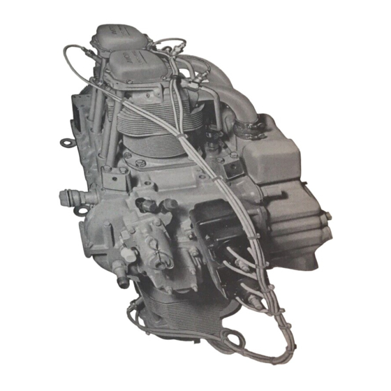
LYCOMING SERIES OPERATOR’S MANUAL TABLE OF CONTENTS Page SECTION 1 DESCRIPTION SECTION 2 SPECIFICATIONS SECTION 3 OPERATING INSTRUCTIONS SECTION 4 PERIODIC INSPECTIONS SECTION 5 MAINTENANCE PROCEDURES SECTION 6 TROUBLE-SHOOTING SECTION 7 INSTALLATION AND STORAGE SECTION 8 TABLES... - Page 8 LYCOMING SERIES OPERATOR’S MANUAL Left Side View – O-320 – 76 Series ¾ Right Rear View – O-320 – 76 Series...
-
Page 9: Description
LYCOMING SERIES OPERATOR’S MANUAL SECTION 1 DESCRIPTION Page General................................1-1 Cylinders............................... 1-1 Valve Operating Mechanism ........................1-1 Crankcase ..............................1-1 Crankshaft ..............................1-1 Connecting Rods ............................1-1 Pistons ................................1-1 Oil Sump ............................... 1-1 Cooling System ............................. 1-2 Induction System............................1-2 Lubrication System............................ - Page 10 This Page Intentionally Left Blank.
- Page 11 SECTION 1 DESCRIPTION General – The Lycoming O-320 aircraft engine is a four cylinder direct drive, horizontally opposed, wet sump, carbureted, air cooled engine. In referring to the location of the various engine components, the parts are described in their relationship to the engine as installed in the airframe.
- Page 12 SECTION 1 LYCOMING SERIES OPERATOR’S MANUAL DESCRIPTION O-320 Cooling System – The engine is designed to be air cooled by air pressure. Baffles are provided to build up a pressure and direct the air through the cylinder fins. The air is then exhausted to the atmosphere through the rear of the lower cowling.
-
Page 13: Specifications
LYCOMING SERIES OPERATOR’S MANUAL SECTION 2 SPECIFICATIONS Page Specifications O-320-H..............................2-1 Accessory Drives Drive Ratio..............................2-1 Direction of Rotation ..........................2-1 Standard Engine Weight ..........................2-1... - Page 14 This Page Intentionally Left Blank.
- Page 15 LYCOMING SERIES OPERATOR’S MANUAL SECTION 2 O-320 SPECIFICATIONS SECTION 2 SPECIFICATIONS O-320-H FAA Type Certificate ............................274 Rated horsepower............................160 Rated speed, RPM............................2700 Bore, inches..............................5.125 Stroke, inches..............................3.875 Displacement, cubic inches.........................319.8 Compression ratio ............................. 9.00:1 Firing order ............................. 1-3-2-4 Spark occurs, degrees BTC..........................25 Valve rocker clearance (hydraulic tappets collapsed) .................
- Page 16 This Page Intentionally Left Blank.
-
Page 17: Operating Instructions
LYCOMING SERIES OPERATOR’S MANUAL SECTION 3 OPERATING INSTRUCTIONS Page General................................3-1 Prestarting Items of Maintenance ......................3-1 Starting Procedures ............................. 3-1 Cold Weather Starting ..........................3-2 Ground Running and Warm-Up ........................ 3-2 Ground Check .............................. 3-3 Operation in Flight Leaning Procedure............................ 3-4 Intake Air Heat Control ........................... - Page 18 This Page Intentionally Left Blank.
-
Page 19: General
WARRANTY BUT WILL SHORTEN THE LIFE OF YOUR ENGINE AFTER ITS WARRANTY PERIOD HAS PASSED. New engines have been carefully run-in by Lycoming and therefore, no further break-in is necessary insofar as operation is concerned; however, new or newly overhauled engines should avoid low power below 65%, during the first 50 hours or until the oil consumption has stabilized. -
Page 20: Cold Weather Starting
SECTION 3 LYCOMING SERIES OPERATOR’S MANUAL OPERATING INSTRUCTIONS O-320 NOTE Cranking periods must be limited to ten (10) to twelve (12) seconds with a five (5) minute rest between cranking periods. a. Carbureted Engines (Cold). (1) Perform pre-flight inspection. (2) Set carburetor heat control in “off” position. -
Page 21: Ground Check
LYCOMING SERIES OPERATOR’S MANUAL SECTION 3 O-320 OPERATING INSTRUCTIONS NOTE Any ground check that requires full throttle operation must be limited to three minutes or less if the indicated cylinder head temperature exceeds the maximum as stated in this manual (page 3-9). -
Page 22: Operation In Flight
The procedures described in this manual provide proper fuel/air mixture when leaning Lycoming engines; they have proven to be both economical and practical by eliminating excessive fuel consumption and reducing damaged parts replacement. It is therefore recommended that operators, of all Lycoming aircraft power plants, utilize the instructions in this publication any time the fuel/air mixture is adjusted during flight. - Page 23 LYCOMING SERIES OPERATOR’S MANUAL SECTION 3 O-320 OPERATING INSTRUCTIONS GENERAL RULES (CONT.) During let-down and reduced power flight operations it may be necessary to manually lean or leave mixture setting at cruise position prior to landing. During the landing sequence set the mixture control in the full rich position, unless landing at high elevation fields where leaning may be necessary.
- Page 24 SECTION 3 LYCOMING SERIES OPERATOR’S MANUAL OPERATING INSTRUCTIONS IO-390 SERIES Figure 3-1. Representative Effect of Leaning on Cylinder Head Temperature, EGT (Exhaust Gas Temperature), Engine Power and Specific Fuel Consumption at Constant Engine RPM and Manifold Pressure...
- Page 25 LYCOMING SERIES OPERATOR’S MANUAL SECTION 3 O-320 OPERATING INSTRUCTIONS To avoid this, all installations are equipped with a system for preheating the incoming air supply to the carburetor. In this way sufficient heat is added to replace the heat loss of vaporization of fuel, and the mixing chamber temperature cannot drop to the freezing point of water (32°F).
-
Page 26: Engine Flight Chart
SECTION 3 LYCOMING SERIES OPERATOR’S MANUAL OPERATING INSTRUCTIONS O-320 9. ENGINE FLIGHT CHART. FUEL AND OIL – Model *Aviation Grade Fuel Minimum O-320-H ........................100/100LL NOTE Aviation grade 100LL fuels in which the lead content is limited to 2 c.c. per gallon are approved for continuous use in these engines. - Page 27 LYCOMING SERIES OPERATOR’S MANUAL SECTION 3 O-320 OPERATING INSTRUCTIONS Average * Oil Inlet Temperature Ambient Air Desired Maximum Above 60°F 180°F (82°C) 245°F (118°C) 30°F to 90°F 180°F (82°C) 245°F (118°C) 0°F to 70°F 170°F (77°C) 225°F (107°C) Below 10°F 160°F (71°C)
- Page 28 SECTION 3 LYCOMING SERIES OPERATOR’S MANUAL OPERATING INSTRUCTIONS O-320 Figure 3-2. Fuel Flow vs Rated Power – O-320-H 3-10...
- Page 29 LYCOMING SERIES OPERATOR’S MANUAL SECTION 3 O-320 OPERATING INSTRUCTIONS Figure 3-3. Sea Level and Altitude Performance – O-320-H 3-11...
- Page 30 This Page Intentionally Left Blank.
-
Page 31: Periodic Inspections
LYCOMING SERIES OPERATOR’S MANUAL SECTION 4 PERIODIC INSPECTIONS Page General................................4-1 Pre-Starting Inspection ..........................4-1 Daily Pre-Flight............................4-2 25-Hour Inspection ............................4-2 50-Hour Inspection ............................4-2 100-Hour Inspection ............................ 4-3 400-Hour Inspection ............................ 4-4 Non-Scheduled Inspections ......................... 4-5... - Page 32 This Page Intentionally Left Blank.
- Page 33 LYCOMING SERIES OPERATOR’S MANUAL SECTION 4 O-320 PERIODIC INSPECTIONS SECTION 4 PERIODIC INSPECTIONS NOTE Perhaps no other factor is quite so important to safety and durability of the aircraft and its components as faithful and diligent attention to regular checks for minor troubles and prompt repair when they are found.
- Page 34 SECTION 4 LYCOMING SERIES OPERATOR’S MANUAL PERIODIC INSPECTIONS O-320 1. DAILY PRE-FLIGHT. a. Be sure all switches are in the “Off” position. b. Be sure magneto ground wires are connected. c. Check oil level. d. See that fuel tanks are full.
- Page 35 LYCOMING SERIES OPERATOR’S MANUAL SECTION 4 O-320 PERIODIC INSPECTIONS c. Lubrication System – (1) Remove oil suction screen and check carefully for presence of metal particles that are indicative of internal engine damage. This step is not feasible unless oil is being changed and should be omitted on installations employing an external full flow oil filter.
- Page 36 6. NON-SCHEDULED INSPECTIONS. Occasionally, service bulletins or service instructions are issued by Lycoming that require inspection procedures that are not listed in this manual. Such publications, usually are limited to specified engine models and become obsolete after corrective modification has been accomplished.
-
Page 37: Maintenance Procedures
LYCOMING SERIES OPERATOR’S MANUAL SECTION 5 MAINTENANCE PROCEDURES Page General................................5-1 Ignition and Electrical System Ignition Harness and Wire Replacement....................5-1 Timing Magnetos to Engine ........................5-1 Internal Timing – Dual Magneto......................5-2 Alternator Output............................. 5-4 Fuel System Repair of Fuel Leaks..........................5-4 Carburetor Fuel Inlet Screen Assembly .................... - Page 38 This Page Intentionally Left Blank.
-
Page 39: Ignition And Electrical System
No attempt is made to include repair and replacement operations that will be found in the applicable Lycoming Overhaul Manual. 1. IGNITION AND ELECTRICAL SYSTEM. -
Page 40: Internal Timing - Dual Magneto
SECTION 5 LYCOMING SERIES OPERATOR’S MANUAL MAINTENANCE PROCEDURES O-320-H (6) Observe that at this time the built in pointer just ahead of the rotor viewing window aligns with the R or L mark on the rotor depending on whether the magneto is of right or left hand rotation as specified on the magneto nameplate. - Page 41 LYCOMING SERIES OPERATOR’S MANUAL SECTION 5 O-320 MAINTENANCE PROCEDURES Figure 5-1. Ignition Wiring Diagram – Dual Magneto (3) Retard Breaker – Remove timing light leads from the main breaker terminals. Attach one positive lead to retard breaker terminal, and second positive lead to the tachometer breaker terminal, if used.
-
Page 42: Alternator Output
Fuel of a lower octane than specified is not to be used. Under no circumstances should automotive fuel be used (regardless of octane rating). NOTE It is recommended that personnel be familiar with the latest revision of Service Instruction No. 1070 regarding specified fuel for Lycoming engines. -
Page 43: Idle Speed And Mixture Adjustment
LYCOMING SERIES OPERATOR’S MANUAL SECTION 5 O-320 MAINTENANCE PROCEDURES d. Air Intake Ducts and Filter – Check all air intake ducts for dirt or restrictions. Inspect and service air filters as instructed in the airframe manufacturer’s handbook. Replace any filter or air ducts that shows signs of deterioration or collapse. -
Page 44: Oil Relief Valve
STD-425 washers under the cap to increase pressure or the use of a spacer (Lycoming P/N 73629 or 73630) to decrease pressure. A modification on later models has eliminated the need for the spacers. Particles of metal or other foreign matter lodged between the ball and seat will result in faulty readings. -
Page 45: Cylinders
LYCOMING SERIES OPERATOR’S MANUAL SECTION 5 O-320 MAINTENANCE PROCEDURES (7) Remove cylinder base nuts, then remove cylinder by pulling directly away from crankcase. Be careful not to allow the piston and connecting rod to drop against the crankcase, as the piston leaves the cylinder. - Page 46 SECTION 5 LYCOMING SERIES OPERATOR’S MANUAL MAINTENANCE PROCEDURES O-320 (5) Reassemble the spring, plunger and socket into the body and secure with a new circlip. NOTE The lifter must be perfectly dry to obtain proper dry tappet clearance. e. Assembly of Valves in Cylinder –...
-
Page 47: Alternator Drive Belt Tension
LYCOMING SERIES OPERATORS MANUAL SECTION 5 O-320 MAINTENANCE PROCEDURES (5) Install cylinder base hold-down nuts and tighten as directed in the following steps. NOTE At any time a cylinder is replaced, it is necessary to retorque the thru-studs on the cylinder on the opposite side of the engine. - Page 48 This Page Intentionally Left Blank.
-
Page 49: Trouble-Shooting
LYCOMING SERIES OPERATOR’S MANUAL SECTION 6 TROUBLE-SHOOTING Page Failure of Engine to Start..........................6-1 Failure of Engine to Idle Properly......................6-2 Low Power and Uneven Running....................... 6-2 Failure of Engine to Develop Full Power....................6-3 Rough Engine ............................... 6-3 Low Oil Pressure............................6-3 High Oil Temperature .......................... - Page 50 This Page Intentionally Left Blank.
-
Page 51: Failure Of Engine To Start
LYCOMING SERIES OPERATOR’S MANUAL SECTION 6 O-320 TROUBLE-SHOOTING SECTION 6 TROUBLE-SHOOTING Experience has proven that the best method of trouble-shooting is to decide on the various causes of the given trouble and then to eliminate causes one by one, beginning with the most probable. The following charts list some of the more common troubles, which may be encountered in maintaining engines;... -
Page 52: Failure Of Engine To Idle Properly
SECTION 6 LYCOMING SERIES OPERATOR’S MANUAL TROUBLE-SHOOTING O-320 TROUBLE PROBABLE CAUSE REMEDY Failure of Engine to Idle Properly Incorrect idle mixture. Adjust mixture. Leak in induction system. Tighten all connections in the induction system. Replace any parts that are defective. -
Page 53: Low Oil Pressure
LYCOMING SERIES OPERATOR’S MANUAL SECTION 6 O-320 TROUBLE-SHOOTING TROUBLE PROBABLE CAUSE REMEDY Failure of Engine to Develop Full Leak in induction system. Tighten all connections and Power replace defective parts. Throttle lever out of adjustment. Adjust throttle lever. Improper fuel flow. -
Page 54: Excessive Oil Consumption
SECTION 6 LYCOMING SERIES OPERATOR’S MANUAL TROUBLE-SHOOTING O-320 TROUBLE PROBABLE CAUSE REMEDY High Oil Temperature Insufficient air cooling. Check air inlet and outlet for deformation or obstruction. Insufficient oil supply. Fill to proper level with specified oil. Wrong grade of oil for season. -
Page 55: Installation And Storage
LYCOMING SERIES OPERATOR’S MANUAL SECTION 7 INSTALLATION AND STORAGE Page Preparation of Engine for Installation....................... 7-1 General................................7-1 Inspection of Engine Mounting ........................7-1 Attaching Engine to Mounts ........................7-1 Oil and Fuel Line Connections ........................7-1 Propeller Installation ........................... 7-1 Preparation of Carburetors for Installation.................... - Page 56 This Page Intentionally Left Blank.
- Page 57 LYCOMING SERIES OPERATOR’S MANUAL SECTION 7 O-320 INSTALLATION AND STORAGE SECTION 7 INSTALLATION AND STORAGE 1. PREPARATION OF ENGINE FOR INSTALLATION. Before installing an engine that has been prepared for storage, remove all dehydrator plugs, bags of desiccant and preservative oil from the engine.
- Page 58 SECTION 7 LYCOMING SERIES OPERATOR’S MANUAL INSTALLATION AND STORAGE O-320 2. PREPARATION OF CARBURETORS FOR INSTALLATION. Carburetors that have been prepared for storage should undergo the following procedures before being placed in service. Carburetor – Remove the fuel drain plug and drain preservative oil. Remove the fuel inlet strainer assembly and clean in a hydrocarbon solvent.
- Page 59 LYCOMING SERIES OPERATOR’S MANUAL SECTION 7 O-320 INSTALLATION AND STORAGE Figure 7-1. Installation Drawing – Left Side View – O-320 – 76 Series Figure 7-2. Installation Drawing – Rear View – O-320 – 76 Series...
- Page 60 This Page Intentionally Left Blank.
- Page 61 LYCOMING SERIES OPERATOR’S MANUAL SECTION 8 TABLES Page Table of Limits ............................. 8-1 Ground Run After Top Overhaul ......................8-2 Flight Test After Top Overhaul........................8-3 Full Throttle HP at Altitude........................8-4 Table of Speed Equivalents ......................... 8-4 Centigrade-Fahrenheit Conversion Table....................8-5...
- Page 62 This Page Intentionally Left Blank.
- Page 63 LYCOMING SERIES OPERATOR’S MANUAL SECTION 8 O-320 TABLES SECTION 8 TABLES TIGHTENING TORQUE RECOMMENDATIONS INFORMATION CONCERNING TOLERANCES AND DIMENSIONS THAT MUST BE MAINTAINED IN LYCOMING AIRCRAFT ENGINES, CONSULT LATEST REVISION OF TABLE OF LIMITS NO. SSP-1776.
- Page 64 SECTION 8 LYCOMING SERIES OPERATOR’S MANUAL TABLES O-320...
- Page 65 LYCOMING SERIES OPERATOR’S MANUAL SECTION 8 O-320 TABLES...
- Page 66 SECTION 8 LYCOMING SERIES OPERATOR’S MANUAL TABLES O-320 FULL THROTTLE HP AT ALTITUDE (Normally Aspirated Engines) Altitude % S.L. Altitude % S.L. Altitude % S.L. H.P. H.P. H.P. 10,000 70.8 19,500 49.1 98.5 11,000 68.3 20,000 48.0 1,000 96.8 12,000 65.8...
- Page 67 LYCOMING SERIES OPERATOR’S MANUAL SECTION 8 O-320 TABLES CENTIGRADE-FAHRENHEIT CONVERSION TABLE Example: To convert 20°C to Fahrenheit, find 20 in the center column headed (F-C); then read 68.0°F in the column (F) to the right. To convert 20°F to Centigrade; find 20 in the center column and read –6.67°C in the (C) column to the left.
- Page 68 SECTION 8 LYCOMING SERIES OPERATOR’S MANUAL TABLES O-320 INCH FRACTIONS CONVERSIONS Decimals, Area of Circles and Millimeters Inch Decimal Area Inch Decimal Area Fraction Equiv. Sq. In. Equiv. Fraction Equiv. Sq. In. Equiv. 1/64 .0156 .0002 .397 .1964 12.700 1/32 .0312...
Need help?
Do you have a question about the O-320 76 Series and is the answer not in the manual?
Questions and answers