
Subscribe to Our Youtube Channel
Related Manuals for Lycoming IO-360-N1A


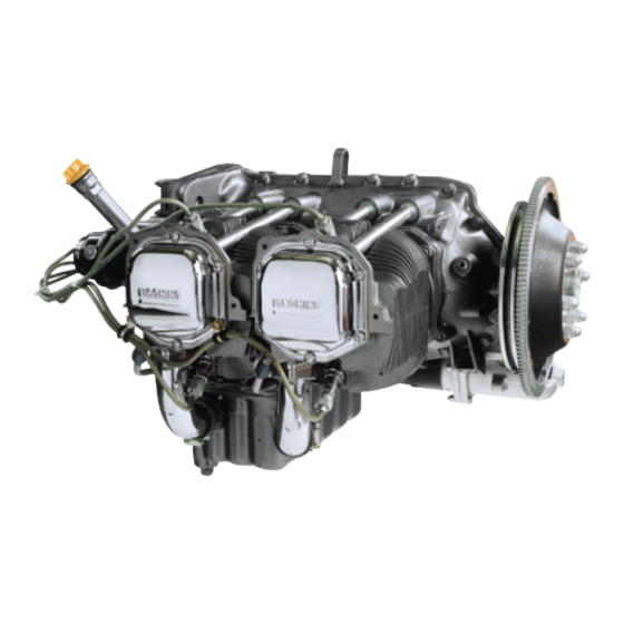
Summary of Contents for Lycoming IO-360-N1A
- Page 1 Engine Installation and Operation Manual IO-360-N1A Engine February 2016 Part No. IOM-IO-360-N1A © 2016 Avco Corporation. All Rights Reserved.
- Page 2 652 Oliver Street Williamsport, PA 17701 USA Phone: U.S. and Canada Toll Free: +1 (800) 258-3279 Factory Direct: +1 (570) 323-6181 Lycoming’s regular business hours are Monday through Friday from 8:00AM through 5:00PM Eastern Time (-5 GMT). Visit us Online: www.Lycoming.com...
-
Page 3: Record Of Revisions
IO-360-N1A Engine Installation and Operation Manual RECORD OF REVISIONS Revision Revised Revision Date Revision Description Original Release of Installation and Operation Manual - Part No. Original IOM-IO-360-N1A © 2016 Avco Corporation. All Rights Reserved Record of Revisions February 2016 Page i... - Page 4 IO-360-N1A Engine Installation and Operation Manual This page intentionally left blank. Record of Revisions © 2016 Avco Corporation. All Rights Reserved Page ii February 2016...
-
Page 5: Service Document List
IO-360-N1A Engine Installation and Operation Manual SERVICE DOCUMENT LIST NOTICE: The following is a list of service documents referenced in or incorporated into the information in this manual. Always refer to the latest revision of any service document for changes or additional information. - Page 6 IO-360-N1A Engine Installation and Operation Manual This page intentionally left blank. Service Document List © 2016 Avco Corporation. All Rights Reserved Page iv February 2016...
-
Page 7: Table Of Contents
IO-360-N1A Engine Installation and Operation Manual TABLE OF CONTENTS Section Page Frontal __________________________________________________________________________ Record of Revisions ..........................i Service Document List ........................iii Table of Contents ..........................v List of Figures ............................. ix List of Tables ............................xi Abbreviations and Acronyms ......................xiii Introduction ............................ - Page 8 IO-360-N1A Engine Installation and Operation Manual Section Page Engine Installation ________________________________________________________________ — Engine Installation Overview ....................17 — Step 1. Install the Engine on Mounts ..................18 — Step 2. Connect the Wiring Harness ..................18 — Step 3. Connect the Linkages ....................18 —...
- Page 9 IO-360-N1A Engine Installation and Operation Manual Section Page Engine Conditions ________________________________________________________________ — Action for Engine Conditions ....................31 —Apply Heat to a Cold Engine ....................32 —Cold Weather Start ......................33 —Engine Operation in Hot Weather ..................34 —Volcanic Ash ........................34 —Overspeed..........................
- Page 10 IO-360-N1A Engine Installation and Operation Manual This page intentionally left blank. Table of Contents © 2016 Avco Corporation. All Rights Reserved Page viii February 2016...
-
Page 11: List Of Figures
IO-360-N1A Engine Installation and Operation Manual LIST OF FIGURES Fig. No. Figure Title Page System Description Section IO-360-N1A Engine Engine Cylinder Crankcase Crankshaft Ignition System Starter Fuel Injection System Lubrication System Cylinder Number Designation Engine Reception and Lift Section Engine Data Plate... - Page 12 IO-360-N1A Engine Installation and Operation Manual This page intentionally left blank. List of Figures © 2016 Avco Corporation. All Rights Reserved Page x February 2016...
-
Page 13: List Of Tables
Prerequisites for Engine Installation Optional Equipment, Recommendations, and Requirements to Prepare the Engine for Installation Engine Installation Section Aircraft Where IO-360-N1A Engines Can Be Installed Aircraft Where IO-360-N1A Engines Cannot be Installed Engine Installation Steps and References Engine Start and Operation Section... - Page 14 IO-360-N1A Engine Installation and Operation Manual This page intentionally left blank. List of Tables © 2016 Avco Corporation. All Rights Reserved Page xii February 2016...
-
Page 15: Abbreviations And Acronyms
IO-360-N1A Engine Installation and Operation Manual ABBREVIATIONS AND ACRONYMS Ampere Brake Horsepower BSFC Brake Specific Fuel Consumption British Thermal Unit Celsius Cylinder Head Temperature Centimeter Exhaust Gas Temperature Environmental Protection Agency Fahrenheit Federal Aviation Administration Federal Aviation (and Space) Regulation Foreign Object Debris Ft.-lb... - Page 16 IO-360-N1A Engine Installation and Operation Manual ABBREVIATIONS AND ACRONYMS (CONT.) Millimeter Mandatory Service Bulletin Newton Meter Part Number Pilot’s Operating Handbook Particles per Million Pounds per Square Inch Revolutions per Minute Society of Automotive Engineers (oil viscosity) Service Bulletin Service Instruction...
-
Page 17: Introduction
IO-360-N1A Engine Installation and Operation Manual INTRODUCTION Engine Model Nomenclature The tables below show the definition of each letter and number for IO-360-N1A engines. Model Number Meaning Fuel Injected Horizontally Opposed Displacement in cubic inches Scope of this Manual This manual supplies instructions (in compliance with FAR 33.5 and 21.50) for engine preparation, installation, and operation of the IO-360-N1A Lycoming aircraft engines. - Page 18 Be sure to read and obey the Warnings, Cautions and Notices in this manual and in service documents. Although Lycoming cannot know all possible hazards or damages, it makes a reasonable effort to supply the best possible guidance and recommended practices for safe operation of its engines.
- Page 19 Supplemental Service Information Refer to the latest revision of Service Letter No. L114 for a list of Lycoming publications available for purchase. Feedback To supply comments, suggestions, or corrections to this manual, either make a call to customer service or use the Lycoming.com website.
- Page 20 IO-360-N1A Engine Installation and Operation Manual This page intentionally left blank. Introduction © 2016 Avco Corporation. All Rights Reserved Page xviii February 2016...
-
Page 21: System Description
IO-360-N1A Engine Installation and Operation Manual SYSTEM DESCRIPTION The Lycoming IO-360-N1A engine (Figure 1) is a direct-drive four-cylinder, horizontally opposed, fuel-injected, air-cooled engine. It has tuned induction, and a down exhaust. NOTICE: Refer to Appendix C for engine performance data. -
Page 22: Crankcase
IO-360-N1A Engine Installation and Operation Manual Crankcase The crankcase (Figure 3) is made up of two casting halves attached by a series of through-studs, bolts and nuts. The crankcase forms the bearings for the camshaft. The camshaft operates the tappets which control opening and closing of the intake and exhaust valves. -
Page 23: Starter
IO-360-N1A Engine Installation and Operation Manual Figure 5 Ignition System Starter The engine can have either a 12V or 24V starter (Figure 6). Refer to Appendix A. Figure 6 Starter © 2016 Avco Corporation. All Rights Reserved System Description February 2016... -
Page 24: Fuel Injection System
IO-360-N1A Engine Installation and Operation Manual Fuel Injection System The fuel injection system (Figure 7) includes: a fuel manifold and fuel injector, four injection nozzles (one per cylinder), a diaphragm-type fuel pump, and fuel lines which connect the fuel injectors to the fuel manifold. Refer to the fuel flow and consumption curves in Appendix C. -
Page 25: Cylinder Number Designations
IO-360-N1A Engine Installation and Operation Manual Cylinder Number Designations The propeller is at the front of the engine and the accessories are at the rear of the engine. When viewed from the top of the engine, the left side cylinders are 2-4. Cylinder 2 is at the front of the engine (Figure 9). - Page 26 IO-360-N1A Engine Installation and Operation Manual This page intentionally left blank. System Description © 2016 Avco Corporation. All Rights Reserved Page 6 February 2016...
-
Page 27: Engine Reception And Lift
1. When the engine is received, make sure that the shipping container or box is not damaged. If the engine crate is damaged, speak to Lycoming’s Service Department and the freight shipper. A. These engines are usually sent in a box where the engine is attached to a pallet within the box. -
Page 28: Engine Preservative Oil Removal
IO-360-N1A Engine Installation and Operation Manual Engine Preservative Oil Removal The engine is sent with preservative oil in the cylinder and preservative oil in the crankcase. Refer to the “Prepare a New, Rebuilt, or Overhauled Engine for Installation” section in the “Requirements for Engine Installation”... -
Page 29: Requirements For Engine Installation
2. Complete the preservative oil removal procedure as follows: A. If any of the dehydrator plugs (which contain crystals of silica gel) break and the crystals fall into the engine, complete the following per the IO-360-N1A Engine Maintenance Manual. Disassemble the affected portion of the engine. - Page 30 3. Examine the cylinder bores with a borescope for rust and contamination. Refer to the IO-360- N1A Engine Service Manual. 4. If any corrosion or unusual conditions are found, speak to Lycoming Engine’s Service Department. 5. Drain preservative oil from the oil sump: A.
- Page 31 IO-360-N1A Engine Installation and Operation Manual 6. Drain the fuel pump: A. Put a collection container underneath the fuel pump. B. Remove the shipping cap installed on the inlet fitting of the fuel pump. C. Disconnect the outlet hose from the outlet fitting on the fuel pump.
- Page 32 7. Remove any other moisture-prevention seals and covers from the engine. IF PRESERVATIVE OIL TOUCHES PAINTED SURFACES, REMOVE THE OIL IMMEDIATELY TO PREVENT DAMAGE TO THE PAINT. NOTICE: To touch-up paint, refer to Chapter 72-10 in the IO-360-N1A Engine Maintenance Manual. 8. Complete the preservative oil removal procedure as follows: A.
- Page 33 F. Safety wire the two oil sump drain plugs in accordance with the standard practices per the latest revision of AC43.13-1B. 12. Remove the oil filter and install a new oil filter. Refer to the IO-360-N1A Engine Service Manual. 13. If a constant speed propeller is to be used: A.
-
Page 34: Step 2. Supply Interface Items
Optional Equipment, Recommendations, and Requirements to Prepare the Engine for Installation Issue Recommendation/Requirement Installation drawings and Installation drawings are available for purchase from Lycoming wiring diagrams Engines. Refer to Appendix B. Magnetos Refer to the magneto manufacturer's documentation for information on various vibrator and switching arrangements. -
Page 35: Step 3. Remove Components
The Type 1 Dynafocal mounts can withstand a 10 G load per FAA FAR requirements. Step 5. Prepare the Aircraft Engine Harness Lycoming Engines can supply a wiring diagram to the aircraft manufacturer, which is used to prepare the aircraft engine harness. - Page 36 IO-360-N1A Engine Installation and Operation Manual This page intentionally left blank. Requirements for Engine Installation © 2016 Avco Corporation. All Rights Reserved Page 16 February 2016...
-
Page 37: Engine Installation
Any FAR Part 25 aircraft Any FAR Part 29 rotorcraft NOTICE: Installation drawings for this engine are available for purchase from Lycoming Engines. Refer to Appendix B for ordering information. To install the engine, refer to the section reference in this chapter for each step in Table 3. -
Page 38: Step 1. Install The Engine On Mounts
IO-360-N1A Engine Installation and Operation Manual Step 1. Install the Engine on Mounts MAKE SURE THAT THE ENGINE MOUNTS ARE ALIGNED AND NOT BENT OR DEFORMED. IF THE ENGINE IS INSTALLED ON DEFORMED ENGINE MOUNTS OR MISALIGNED, THE ENGINE CAN BE PUT UNDER UNUSUAL STRESS WHICH CAN CAUSE MALFUNCTION. -
Page 39: Step 8. Connect Fuel Lines
A. Make sure that each fuel line is intact. Not bent or damaged, and does not have any kinks or dents. The fuel line must be intact. NOTICE: Refer to Chapter 73-10 in the IO-360-N1A Engine Maintenance Manual for suggested routing and configuration arrangement diagrams for fuel lines on this engine. -
Page 40: Step 10. Install Components That Had Been Removed Before Engine Installation
IO-360-N1A Engine Installation and Operation Manual 3. When making oil line connections: Align the oil line with the fitting for best orientation (without kinks or sharp bends). Torque the fitting to the torque value in the latest revision of the Service Table of Limits - SSP-1776. -
Page 41: Step 12. Add Fuel
IO-360-N1A Engine Installation and Operation Manual Step 12. Add Fuel DETONATION CAN OCCUR IF THE INCORRECT FUEL IS USED. DETONATION CAN INCREASE ENGINE CYLINDER TEMPERAURE AND PRESSURE AND CAUSE DAMAGE TO THE ENGINE. Add the correct fuel. Refer to Appendix A or the latest revision of Service Instruction No. SI-1070 for approved fuels for this engine. - Page 42 IO-360-N1A Engine Installation and Operation Manual 8. Pre-oil start cycle: Energize the starter for 10 seconds and look for evidence of oil pressure of at least 25 psi (172 kPa) within 10 seconds. If there is no oil pressure within 10 seconds, stop energizing the starter. Wait at least 30 seconds and repeat the pre-oil start cycle.
-
Page 43: Engine Start And Operation
SPECIFICATIONS IN THIS MANUAL. YOU ALSO MUST COMPLETE THE RECOMMENDED SERVICE PROCEDURES IN ACCORDANCE WITH THE IO-360-N1A ENGINE SERVICE MANUAL FOR THIS ENGINE. Before Engine Start Before a newly installed/rebuilt/repaired/overhauled or stored engine can be used for flight, all of the steps shown in Table 1 must be done in the sequence shown. -
Page 44: Step 1. Prepare An Engine For First Time Operation
IO-360-N1A Engine Installation and Operation Manual Step 1. Prepare an Engine for First-Time Operation 1. After any of the following actions on a newly installed/rebuilt/repaired/overhauled or stored engine, complete the Pre-Flight Inspection for First-Time Operation Checklist to make sure that the engine is operating correctly after: ... -
Page 45: Pre-Flight Inspection For First Time Operation Checklist
IO-360-N1A Engine Installation and Operation Manual Pre-Flight Inspection for First-Time Operation Checklist (Cont.) Requirement Comments Done Make sure that the induction air filter is clean and securely in place. Examine the engine, propeller hub area, and cowl for Identify and correct the cause of indication of fuel and engine oil leaks. -
Page 46: Step 2. Start The Engine
If the engine is to be operated at temperatures over 90°F (32°C), refer to “Engine Operation in Hot Weather” in the “Engine Conditions” chapter in this manual. NOTICE: The following is Lycoming Engine’s recommended start procedure. If there is any variation between the start procedure in the aircraft manufacturer’s Pilot Operating Handbook (POH) and Lycoming Engine’s recommended start procedure, follow the... - Page 47 IO-360-N1A Engine Installation and Operation Manual DO NOT ENERGIZE THE STARTER FOR PERIODS OVER 10 SECONDS. LET THE STARTER COOL FOR 30 SECONDS AFTER EACH ENERGIZATION. IF THE STARTER FAILS TO ENERGIZE AFTER TWO ATTEMPTS, IDENTIFY AND CORRECT THE CAUSE. DO NOT TRY MORE THAN FIVE ENGINE STARTS WITHIN A 2-MINUTE PERIOD.
-
Page 48: Magnetic Drop-Off Check
IO-360-N1A Engine Installation and Operation Manual 16. Complete a magneto drop-off check as follows for all three cycles RIGHT/LEFT/BOTH. A. Move the propeller control through its complete range as a check for operation and return to the full low pitch position. Full feathering check (twin engine) on the ground is not... -
Page 49: Step 4. Operate The Engine
NOTICE: After 25 hours of operation, change the oil. Examine the oil filter and screen. Refer to Chapter 12-10 in the IO-360-N1A Engine Service Manual. 4. Examine the air filters every other flight for dirt and be prepared to clean or replace them if necessary. -
Page 50: Step 5. Stop The Engine
IO-360-N1A Engine Installation and Operation Manual 5. Operate the engine at maximum power mixture for performance cruise powers and at best economy mixture for economy cruise power; unless otherwise specified in the POH. Refer to Appendix A. 6. During let-down flight operations, it could be necessary to manually lean fuel-injected engines for smooth operation. -
Page 51: Engine Conditions
Then slowly increase rpm back to the desired operational rpm. Complete a safe landing. Identify and correct the cause. Propeller strike, sudden stoppage Make a safe landing. Refer to the IO-360-N1A Engine and lightning strikes Maintenance Manual for corrective action. -
Page 52: Apply Heat To A Cold Engine
50°F (10°C) per minute. Overheating Make a safe landing as soon as possible, and identify and correct the cause. Refer to the IO-360-N1A Engine (The temperature of the system Maintenance Manual components is greater than the maximum design operating temperature for the components.) -
Page 53: Cold Weather Start
“Cold Weather Start” in this chapter. Cold Weather Start NOTICE: The following is Lycoming Engine’s recommended procedure for cold weather engine starts. Refer to the aircraft manufacturer’s Pilot’s Operating Handbook (POH) for in- flight recommendations during cold weather. -
Page 54: Engine Operation In Hot Weather
F. Continue to closely monitor temperatures. Volcanic Ash 1. Given the dynamic conditions of volcanic ash, Lycoming’s recommendation is NOT to operate the engine in areas where volcanic ash is present - in the air or on the ground. Refer to the latest revision of Service Instruction No. -
Page 55: Overspeed
1. Complete a check of the oil level in the oil sump. Drain the oil, if necessary, to measure the oil quantity. Refer to Chapter 12-10 in the IO-360-N1A Engine Service Manual. 2. If the oil level is sufficient, complete a check of the accuracy of the oil pressure indication system. - Page 56 4. Examine the oil suction screen at the oil sump and the oil filter for blockage or metal deposits. If metal or blockage is found, remove the material and identify the origin of material. Correct the root cause. Refer to Chapter 12-10 in the IO-360-N1A Engine Service Manual.
-
Page 57: Flight Test
IO-360-N1A Engine Installation and Operation Manual FLIGHT TEST As shown in the “Engine Start and Operation” chapter of this manual, an operational test and a pre- flight ground run-up must be done before approval by an authorized inspector for a flight test. This flight test, which is part of the required engine break-in field procedure, is necessary to make sure that the engine and aircraft are in compliance with all of the manufacturer’s performance and... - Page 58 Complete this flight test again, up to and including this step before releasing the aircraft for service. M. Drain the oil per the “Oil Change Procedure” in Chapter 12-10 of the IO-360-N1A Engine Service Manual. N. Remove the oil suction screen and the oil pressure screen or oil filter to look for any blockage or contamination.
-
Page 59: Engine Preservation And Storage
If the engine cannot be operated at the recommended oil temperatures, speak with the aircraft manufacturer about the use of oil cooler winterization plates. NOTICE: The Lycoming warranty does not include corrosion unless otherwise identified on the notice tag for new, rebuilt, or overhauled engines sent from Lycoming Engines. -
Page 60: Engine Preservation - 30 To 60 Days
2. Stop the engine. 3. Drain the lubricating oil from the sump or system per Chapter 12-10 in the IO-360-N1A Engine Service Manual. 4. Wash and brush the oil suction screen with Low VOC mineral spirits. - Page 61 NOTICE: Make sure the oil is hot at the nozzle before spray application to the cylinders. 14. Remove both spark plugs from each cylinder. Refer to Chapter 74-20 in the IO-360-N1A Engine Service Manual. 15. Put the spray gun in either of the spark plug holes. Apply the preservative oil mixture to each cylinder, one at a time.
-
Page 62: Fuel Injector Preservation
Engine Preservation - 61 to 180 Days New, rebuilt, and overhauled engines from Lycoming Engines have preservation oil for 60 days per the tag on the outside of the engine box. The date of preservation is shown on the sticker on the outside corner of the engine box with the gross weight or the date written on the top of the box following a “Preservation Date”... -
Page 63: Engine Preservation - 181 Days Or More
Cold Weather Storage In cold weather, if possible, store the aircraft in a heated hangar between flights. Add oil to the engine as required with the specified oil grade (Appendix A). Refer to the IO-360-N1A Engine Service Manual. Long-Term Storage of Engines that Use Automotive Fuel If automotive fuel is used to operate this engine per the latest revision of Service Instruction No. - Page 64 IO-360-N1A Engine Installation and Operation Manual NOTICE: Aviation fuel can be mixed with the automotive fuel. The goal is to have more than 50% aviation fuel in the fuel tanks during storage to prevent possible formation of undesirable deposits. 3. Operate the engine for a minimum of 45 minutes with the oil temperature at 180ºF (80ºC) to work the aviation and automotive fuel mixture through the engine and fuel lines.
-
Page 65: Appendix Aengine Specifications And Operating Limits
IO-360-N1A Engine Installation and Operation Manual APPENDIX A ENGINE SPECIFICATIONS AND OPERATING LIMITS Table A-1 IO-360-N1A Engine Specifications Number of Cylinders Cylinder Arrangement - Firing Order 1-3-2-4 Spark Plugs Spark plug advance 25º BTC Maximum Continuous Horsepower & Brake Specified... - Page 66 IO-360-N1A Engine Installation and Operation Manual Table A-1 (Cont.) IO-360-N1A Engine Specifications Oil Grade at Temperatures between 30°F to 90°F (-1°C to 32°C) Oil Grade at Temperatures between 0°F to 70°F (-18°C 30, 40 or 20W-40 to 21°C) Oil Grade at Temperatures below 10ºF (-12ºC) 30 or 20W-30 The correct grade of oil to be used is based on environmental conditions.
-
Page 67: Table Of Operating Limits For Io-360-N1A Engine
IO-360-N1A Engine Installation and Operation Manual Table A-2 Table of Operating Limits for IO-360-N1A Engine Oil Pressure - Minimum Idling 25 psi 172 kPa Oil Pressure - Operating (rear of engine) 55 to 95 psi 379 to 655 kPa Oil Pressure - Starting, Warm-up, Taxi,... -
Page 68: Accessory Drives For Io-360-N1A Engines
* Except for torque limitation and rotation ** Except for torque limitation *** With compressor pulley diameter of 6.00 inches For any possible additional optional starters and alternators, refer to the latest revision of Lycoming Service Instruction No. SI-1154. Appendix A ©... -
Page 69: Appendix B - Installation And Wiring Diagrams
APPENDIX B INSTALLATION AND WIRING DIAGRAMS NOTICE: Installation drawing (04C63626) is available for purchase from Lycoming Engines for the IO-360-N1A engine. Contact the Publications Clerk at Lycoming Engines at 570- 327-7274. © 2016 Avco Corporation. All Rights Reserved Appendix B... - Page 70 IO-360-N1A Engine Installation and Operation Manual This page intentionally left blank. Appendix B © 2016 Avco Corporation. All Rights Reserved Page 50 February 2016...
-
Page 71: Appendix Cperformance Data
IO-360-N1A Engine Installation and Operation Manual APPENDIX C PERFORMANCE DATA Figure C-1 Sea Level and Altitude Performance © 2016 Avco Corporation. All Rights Reserved Appendix C February 2016 Page 51... - Page 72 IO-360-N1A Engine Installation and Operation Manual Figure C-2 Minimum Fuel Flow vs. Nozzle Pressure Appendix C © 2016 Avco Corporation. All Rights Reserved Page 52 February 2016...
- Page 73 IO-360-N1A Engine Installation and Operation Manual Figure C-3 Fuel Consumption vs. Actual Brake Horsepower © 2016 Avco Corporation. All Rights Reserved Appendix C February 2016 Page 53...
- Page 74 IO-360-N1A Engine Installation and Operation Manual Figure C-4 Cooling Air Requirements Appendix C © 2016 Avco Corporation. All Rights Reserved Page 54 February 2016...
Need help?
Do you have a question about the IO-360-N1A and is the answer not in the manual?
Questions and answers