
Subscribe to Our Youtube Channel
Related Manuals for SKF LUBRILEAN Basic


Summary of Contents for SKF LUBRILEAN Basic
- Page 1 ® Basic Minimum-quantity Lubrication UBRI ® Smart System for External Lubrication UBRI Operating Manual Version 03...
-
Page 3: Table Of Contents
Imprint Contents The operating manual is part of the scope of Part A: General Operating Manual supply of a SKF minimum-quantity central lubri- Contents .......... 0 - 1 cation system. Maintenance........A - 10 Filling with lubricant ......... A - 10... -
Page 4: Ec Declaration Of Conformity And Manufacture
EC Declaration of Conformity and Manufacture Page 0 - 2 EC Declaration of Confor- mity and Manufacture... - Page 5 EC Declaration of Conformity and Manufacture Page 0 - 3...
- Page 6 EC Declaration of Conformity and Manufacture Page 0 - 4...
-
Page 7: Lubri Lean ® Basic
® Basic Minimum-quantity Lubrication UBRI ® Smart System for External Lubrication UBRI Part A General Operating Manual... - Page 9 Systems Germany AG may be gers or work which requires spe- chasing a SKF minimum-quantity central lubri- used only in compliance with cation system. Our high-quality systems were cial caution is described.
-
Page 10: Safety Instructions
The lubricants stipulated for use in SKF mini- for each lubricating point. The lubricant amount ing any work on it, e.g. cleaning, mum-quantity central lubrication systems have is set manually. -
Page 11: Functional Description
SKF. In the case of a malfunction, the system must be Aerosol Production disconnected from the compressed air supply ®... -
Page 12: Design And Function
Smart are described in the cor- UBRI control valves mounted on the lubricant reserve responding chapters. Corresponding operating The lubricants stipulated for use in SKF mini- container regulate the necessary lubricant and elements of both systems types are designated mum-quantity central lubrication systems have atomizer amount as well as set the inner pres- by the same numbers. -
Page 13: Installation
Installation Page A - 5 Installation For this reason only lubricants provided by SKF Setup First filling may be used (see table A - 1). The minimum-quantity lubrication system The lubricant reserve container should be set up in the immediate vicinity of the... -
Page 14: Connections
Ensure that the main air valve is vation valve. The other end of the cable is con- closed before connecting the lubricants provided by SKF may be used. nected to a 24 V DC output on the processing compressed air line. -
Page 15: First Operation
First Operation Page A - 7 First Operation completely open the lubricant control valve The first operation of the minimum-quantity lu- brication system involves the flooding of the switch the solenoid valves (11) at the control (4) in order to increase the lubricant flow, transport lines, the setting of operating parame- ters and a functional check. -
Page 16: Checking The Settings
Operation Page A - 8 Operation Information on operation of the minimum- We recommend ascertaining and optimising the Checking the Settings quantity lubrication system can be found in the necessary settings for your application by un- Direct the spray nozzle toward the cutting edge chapter on the respective system type. -
Page 17: Failures
Failures Page A - 9 Failures The following prerequisites must be met for the If, however, failures nevertheless arise, they can compact system to function faultlessly: usually be quickly remedied as long as there is The system has been connected correctly. no functional failure of the system. -
Page 18: Maintenance
Do not mix different lubricants together unless you have the ex- Filling with lubricant Use a funnel to fill the container with lubricant to press consent of SKF to do so. the maximum level marking. Otherwise damages could arise, The lubricant reserve container... -
Page 19: Draining Lubricant
The lubricant container must not Close the drainage opening be disassembled; this would in- tightly after draining lubricant. validate any warranty claims. SKF LUBRICATION SYSTEMS GERMANY AG assume no liability for damages which accrue from improper installation work on the mini- mum-quantity lubrication system. -
Page 20: Closing Down
If you want to bring the minimum-quantity lubri- cation system to a permanent standstill, please comply with the legal stipulations for disposal of oil-containing components. The system can also be taken back by SKF for disposal if the costs are covered. - Page 21 ® Basic Minimum-quantity Lubrication UBRI System for External Lubrication Part B Device description...
-
Page 23: Ubri Lean
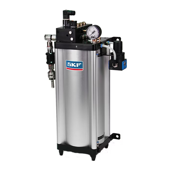
® Basic - Design and Function Page B - 1 UBRI Design and Function Figure B - 1 shows the design of the minimum- The solenoid valve is actuated via a 24V DC Atomizer air valve (3) ® quantity lubrication system L Basic. - Page 24 ® Basic - Design and Function Page B - 2 UBRI 357,5 91.5...
-
Page 25: Indicators
® Basic - Design and Function Page B - 3 UBRI Indicators Connections Filling level indicator (6) Compressed air connection (1) A riser is installed on the front side of the lubri- The minimum-quantity lubrication system ® cant reserve container from which the filling le- Vario has an NG8 coupling socket UBRI vel of the lubricant reserve container can be... -
Page 26: Installation And Connection
® Basic - Installation and Connection Page B - 4 UBRI Installation and Connection The system may be connected only by accordingly qualified and instructed personnel. Comply with the notes in this operating manual. The minimum-quantity lubrica- tion system may be operated only under the specified maxi- mum operating temperature. -
Page 27: Specifications
® Basic - Specifications Page B - 5 UBRI Specifications ® Table B - 1. Specifications for the system L Basic UBRI ® Designation Unit Basic UBRI Container Housing design Metal Installation position Vertical Filling amount Oil consumption ml/h 0-100 Aerosol outlets 2 - 8, upward Outer dimensions of aerosol container... - Page 28 ® Basic - Specifications Page B - 6 UBRI...
- Page 29 ® Smart Minimum-quantity Lubrication UBRI System for External Lubrication Part C Device description...
-
Page 31: Design And Function
® Smart - Design and Function Page C - 1 UBRI Design and Function Figure C - 1 shows the design of the minimum- Pressure reducing valve (5) Lubricant inlet (8) ® quantity lubrication system L Vario. UBRI The pressure reducing valve regulates the inner The lubricant inlet is closed with a screw. - Page 32 ® Smart - Design and Function Page C - 2 UBRI 56,5 52,5 Max. - max. Min. - min. 0,3 l M12x1...
-
Page 33: Indicators
® Smart - Installation and Connection Page C - 3 UBRI Installation and Connection The minimum-quantity lubrica- tion system may be operated Pressure indicator Indicators only under the specified maxi- The pressure gauge (10) installed on the cover mum operating pressure. Higher Filling level indicator (7) plate of the lubricant reserve container indicates pressures are dangerous for both... -
Page 34: Specifications
® Smart - Specifications Page C - 4 UBRI Specifications ® Table C - 1. Specifications for the system L Vario UBRI ® Unit Basic Designation UBRI Container Housing design Metal Installation position Vertical Filling amount 0.3; 0.5; 0.8 Aerosol outlets 1 - 2, upward Outer dimensions 0.3 l filling a-... - Page 35 Notes...
- Page 36 Notes...
- Page 37 Notes...
- Page 38 Notes...
- Page 40 SKF Lubrication Systems Germany AG Motzener Straße 35/37 12277 Berlin Postfach: 970444, 12704 Berlin Telefon: (++49) 30-7 20 02-0 Fax: (++49) 30-7 20 02-111 E-Mail: lubrication-germany@skf.com WWW: www.skf.com/schmierung 951-130-196 April 2009...
Need help?
Do you have a question about the LUBRILEAN Basic and is the answer not in the manual?
Questions and answers