
Related Manuals for SKF VectoLub VE1B


Summary of Contents for SKF VectoLub VE1B
- Page 1 Installation and commissioning VE1B systems SKF VectoLub Version Date of issue October 2020 Publication number 951-130-441 Languages Country/Countries EN …...
- Page 3 Minimal quantity lubrication system VE1B English translation of the original installation and operation manual...
-
Page 4: Imprint
FRANCE dards and regulations on documentation. Tel. +33 (0) 247 403 087 © SKF Or an SKF Service Centre, the addresses of which are given on our website: This documentation is protected by copy- right. All rights reserved. The photomechan- lubrication-france@skf.com... -
Page 5: Table Of Contents
Contents Imprint ......2 3. Design and function ... .13 7.2 Permanent shutdown. -
Page 6: Information Concerning The Ec Declaration Of Incorporation
EC Declaration of Incorporation in accordance with EC-Machinery Directive 2006/42/EC, Appendix II Part B The manufacturer SKF France SAS, 204, Bld Charles de Gaulle, B.P. 239 – 37540 St-Cyr-sur-Loire – FRANCE, declares herewith the confor- mity of the partly completed machine... - Page 7 The partly completed machine must not be put into service until the final machinery into which it is to be incorporated has been declared in conformity with the provisions of the EC Machinery Directive 2006/42/EC and other relevant Directives. St Cyr-sur-Loire, January 15 , 2015 Guillaume Amilien Gérard Gaudin R&D Manager Production unit manager SKF France SKF France Lubrication Business Unit Lubrication Business Unit...
-
Page 8: General
General Table 1 Hazard symbols Meaning of symbols and Symbol Standard Meaning corresponding information In this manual, the symbols and safety DIN 4844-2 W000 General hazard wordings shown on this page are intended to communicate a particular risk to persons, material assets, or the environment. -
Page 9: Safety Instructions
These instructions must be read purpose is considered unintended. and understood by all persons Products of SKF must not be used in con- who are involved with the installation, junction with substances and mixtures clas- operation, maintenance, and repair of sified as hazardous by the Annex I part 2-5 the product. -
Page 10: Authorized Personnel
1.2 Authorized personnel 1.3 Danger relating to electric 1.4 Danger relating to system current pressure The products described in the installation in- structions may only be installed, operated, maintained, and repaired by qualified ex- The electrical connection for the described perts. -
Page 11: Warranty And Liability
1.5 Warranty The instructions do not contain any informa- tion on the warranty. This can be found in the General Conditions of Sales, which are available at: www.skf.com/lubrication. -
Page 12: Lubricants
Should there be a need to use the product to convey media other than lubricants or hazardous substances, this must be dis- cussed with SKF first and the company must give express written permission. The intended use of this product is for the... -
Page 13: Selection Of Lubricants
(or maintenance person) who must You can request an overview of lubricant finally select the appropriate lubricant, with tests offered by SKF from our Service Center. the help of the lubricant supplier. When se- lecting a lubricant, the type of bearing/wear You must observe the machinery 2.3 Approved lubricants... -
Page 14: Lubricants And The Environment
2.4 Lubricants and the 2.5 Danger relating to D A N G E R ! environment lubricants Different lubricants must not be mixed together. Doing so can cause damage and require extensive cleaning of the products/centralized lubrication system. To prevent confusion, we recom- D A N G E R ! D A N G E R ! mend that you attach information indi-... -
Page 15: Design And Function
3. Design and function Refer to safety precautions in the lubricant If a minimal quantity lubrication manufacturer's material safety data sheet. unit is not listed in table 1, please Lubricants are hazardous substance. It is refer to the delivered technical sheet to 3.1 Versions essential to respect any safety instructions know the specific technical data of the... - Page 16 Table 1 Lubrication units VE1B No.: VE1B – – __ __ + __ __ __ Control type 0 = without P = pneumatic pulse generator E = solenoid valve Pumps A = setting with metering rings, 3 to 30 mm / stroke, stainless steel and brass B = setting with thumb wheel, 7 to 30 mm / stroke, stainless steel and brass...
-
Page 17: Construction
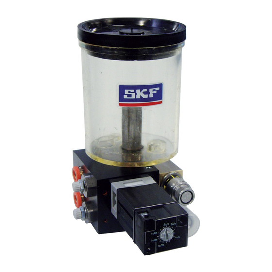
3.2 Construction The VE1B unit might have a pneumatic The VE1B unit is a compact lubrication sys- pulse generator or a pneumatic solenoid tem with all functions joined on a common valve for the actuation and the working fre- ground plate. quency adjustment of the micropump(s). - Page 18 Minimal quantity lubrication system VE1B Fig. 1 1 reservoir 0,3 l 2 coaxial outlet 3 pneumatic pulse generator 4 micropump, setting with thumb wheel 5 carrier air pressure regulator 6 air inlet port (beneath) 7 Solenoid valve 8 lubricant inlet port 9 micropump, setting with metering rings...
- Page 19 Fig. 2 Table 2 VE1B dimensions VE1B dimensions Number of micropumps...
-
Page 20: Function
3.3 Function The low-pressure carrier air and lubricant When the VE1B unit is switched on, it is sup- are simultaneously transported via the co- plied with compressed air (5 to 8 bars) and axial hose to the nozzle. The carrier air is with lubricant (0,1 to 0,5 bar). -
Page 21: Installation Instructions
4. Installation 4.1 Positioning and C A U T I O N ! installation instructions The lubrication system must not be tipped over or thrown. The minimal quantity lubrication system de- The system must be protected from mois- scribed in the mounting instructions may ture and vibrations but on the other hand only be installed, operated, maintained, and Country-specific accident prevention reg-... -
Page 22: Outlet Connection
7 bars. side of the one for lubricant. The coaxial line (from 1 to 5 m*) is connect- ed to the VE1B outlet port by means of quick-release connectors. *) For greater line length, please contact the SKF service center. - Page 23 The length of the coaxial line between the outlet port of the module and the nozzle has to be between 1 and 5 m. For greater length, please contact the SKF service center. Cross-section view of the outlet port 1 Upper quick-release connector...
- Page 24 Step 1 († fig. 6). • Unscrew and remove the nozzle (1) from the end tube (rigid or articulated) (3). • Slip the capillary (7) into the quick con- nector (6) of the fixing block (5) until it is coming out of the end tube (3). Step 2 •...
- Page 25 Connection coaxial line/nozzle Fig. 6 1 Nozzle 2 Union end tube - nozzle 3 End tube 4 Union fixing block - end tube 5 Fixing block 6 Quick-release connector 7 Capillary tube of the coaxial line 8 Outer tube of the coaxial line 9 Coaxial line 10 Quick-release connector Step 1...
-
Page 26: Electric Connection
4.4 Electric connection Fig. 7 D A N G E R ! The supply voltage on site must agree with the information on the codifi- cation of the VE1B unit. Check the fusing ➁ ➀ of the circuit. Use only the original fuse with the required ampere value. -
Page 27: Transport, Delivery And Storage
5.1 Transport Keep the packaging material until any and all be screened SKF products are packaged in accordance problems have been clarified. 5.3.3 Storage – general information with the regulations of the recipient country and in accordance with DIN ISO 9001. -
Page 28: Commissioning
6. Commissioning 6.2 Bleeding and C A U T I O N ! commissioning Only clean lubricant may be used. Contaminated lubricants can result in 6.1 General Before starting the VE1B unit, check that all serious system malfunctions. The minimal quantity lubrication system de- outer connections (reservoir, air supply, lube scribed here runs automatically. -
Page 29: Micropump Flow Rate Adjustment
6.3 Micropump flow rate To ensure the good function of the In the case of a VE1B unit with adjustment micropumps with thumb wheel, only 3 micropumps, the unused the minimal flow rate has to be above 7 outlet for air has to be closed. Therefore There are two different possibilities to adjust /stroke. - Page 30 Fig. 9 6.3.1 Adjustment with thumb wheel • Remove the metering ring (when one) and • Remove the protection cap from the put the new metering ring. Figure of de- Micropump with thumb wheel thumb wheel. livered volume is embossed on every me- •...
-
Page 31: Pneumatic Pulse Generator
6.3.3 Neutralizing the micropump quency of all micropumps. The frequency is When the pressure regulator is delivery indicated on the pulse generator in pulses completely turned to the right, The micropump lubricant outflow can be (piston stroke) per second. The values on the there is no more carrier air flow. - Page 32 Table 3 Table 2 The Vectometer shows different flow rate (in mm per minute) according to the lubricant flow rate and the working frequency of the micropump. Setting [mm stroke] Micropump working frequency [stroke/minute] 25.5 12.5 42.5 1,200 1,500 1,800 37.5 127.5 1,350...
-
Page 33: Reservoir Filling
If you wish to shut down the product tem- The system can also be taken back by SKF porarily, refer also to the instructions in the for disposal if the costs are covered. Ensure the reservoir is filled with... -
Page 34: Maintenance
• Regularly check the level of lubricant in the reservoir and, if necessary, replace re- SKF is not liable for damage caused by im- C A U T I O N ! fill the reservoir. -
Page 35: Failures
SKF Service. not connected to a power supply. The supply voltage must be turned off before Only original SKF spare parts may any product components are opened. - Page 36 Table 4 Failure analysis and remedy Problem Cause Remedy No lubricant at the nozzle No lubricant at the nozzle outlet Check the lubricant level in the reservoir and fill it if necessary outlet Check the tightness of the line reservoir/VE1B unit (connectors and hose). If necessary change the faulty part.
- Page 37 Following table 4 Failure analysis and remedy Problem Cause Remedy The micropump does not work Wrong setting of the metered volume of the Check the setting of the metered volume of the micropump micropump No air supply to the micropump Check the good function of the general air solenoid valve or of the air solenoid valve of the micropump •...
-
Page 38: Technical Data
10. Technical data Table 5 Technical data VE1B system VE1B unit Number of outlets 1 to 4 Min. air inlet 400 Nl/min, dry and filtered air (5 μm) Air inlet pressure 5 to 8 bars Micropump flow rate 3, 5, 10, 15, 20 and 30 mm /stroke (small flow, metering rings) 7 to 30 mm / stroke (small flow, thumb wheel) -
Page 39: Spare Parts And Accessories
Table 6 accessories List of spare parts Order No. Designation Only original SKF spare parts may PV.1975.0.30 Set of metering rings for micropump (0 to 30 mm be used. It is prohibited for the PV.2063.0.90 Set of metering rings for micropump (0 to 90 mm... - Page 40 SKF France Important information on product usage SKF and Lincoln lubrication systems or their components are not Lubrication Business Unit approved for use with gases, liquefied gases, pressurized gases in 204, bld Charles de Gaulle, B.P. 239 solution and fluids with a vapor pressure exceeding normal atmospheric 37540 St-Cyr-sur-Loire –...
Need help?
Do you have a question about the VectoLub VE1B and is the answer not in the manual?
Questions and answers