
Related Manuals for SKF LINCOLN FF Series


Summary of Contents for SKF LINCOLN FF Series
- Page 1 Operating instructions FF and FB according to ATEX Directive 2014/34/EU EEX multiline pump units foh use in phoghessive centhalized lubhication systems Version 02 951-180-076-EN...
- Page 2 EU Declaration of Conformity EU Declaration of Conformity pursuant to ATEX Directive 2014/34/EU, Annex X The manufacturer, SKF Lubrication Systems Germany GmbH, Walldorf Plant, Heinrich-Hertz-Straße 2-8, DE - 69190 Walldorf hereby declares the confor- mity of the device: Designation: Multiline pump unit, FF...A4056; FF...A4060; FF...A4070; FF...A4073 FB...D4128;...
-
Page 3: Masthead
LKF Lubrication Lystems Germany GmbH Disclaimer of liability Thaining Address of manufacturer plants The manufacturer shall not be held liable for SKF conducts detailed training in order to damage resulting from: enable the maximum safety and efficiency. ○ Improper usage, assembly, operation, Headquarters... -
Page 4: Table Of Contents
Table of contents Table of contents Masthead ..................3 Explanation of symbols and signs ............7 1.22 Nullification of ATEX approval .............20 Lafety instructions ................ 9 General safety instructions ..............9 1.23 Operation in potentially explosive atmospheres .......20 General behavior when handling the product ........9 1.24 Explosion protection marking .............20 Intended use ..................10... - Page 5 Table of contents Technical data ................32 Assembly ..................52 FF multiline pump unit, characteristics for designs 1M and 2M ..32 General information ................52 4.1.1 VEM motor characteristics, design “tb” (dust) ......33 6.1.1 Assembly location ................53 4.1.2 Siemens motor characteristics, design “tb” (dust) ......35 Mechanical connection .................53 4.1.3 VEM-Sondermotorkenngrößen, Ausführung "tb"...
- Page 6 Table of contents Initial commissioning ..............78 Repairs ..................92 Venting of pump elements ..............78 12.1 Removing a pump element ..............92 Varying pump displacement ..............79 12.2 Installing a pump element ..............93 Filling with lubricant ................80 Lhutdown, disposal ..............96 Inspections before initial commissioning ...........82 13.1 Temporary shutdown ................96 Operation ..................
-
Page 7: Explanation Of Symbols And Signs
Exmlanation of symbols, signs, and abbreviations Explanation of symbols and signs General warning Risk of electrical shock Risk of slipping Hot surfaces Being drawn into machinery Crushing hazard Pressure injection Suspended load Electrostatic sensitive Potentially explosive Unauthorized persons must be Pressure injection components atmosphere... - Page 8 Exmlanation of symbols, signs, and abbreviations Abbheviations and convehsion factohs regarding °C degrees Celsius °F degrees Fahrenheit approx. approximately Kelvin ounce i.e. that is Newton fl. oz. Fluid ounce incl. including hour inch min. minimum second pound per square inch max.
-
Page 9: Lafety Instructions
1. Safety instructions 1. Lafety instructions 1.1 General safety instructions 1.2 General behavior when handling the product ○ All safety regulations and in-house ○ The operator must ensure that the in- ○ The product may only be used in aware- instructions relevant to the particular structions are read by all persons tasked ness of the potential dangers, in proper... -
Page 10: Intended Use
ATEX. property damage. The use of synthetic and ○ in areas with damaging radiation (e.g., biodegradable oils or greases requires prior approval from SKF Lubrication Systems ionizing radiation) Germany GmbH. ○ Use to feed, forward, or store hazardous... -
Page 11: Painting Plastic Components
1. Safety instructions 1.5 Painting plastic components 1.7 Prohibition of certain activities 1.8 Inspections prior to delivery The painting of all plastic components and The following activities must be performed The following tests were performed prior to seals of the products described here is pro- only by employees of the manufacturer or delivery: hibited. -
Page 12: Referenced Documents
1. Safety instructions 1.9 Referenced documents 1.10 Markings on the product In addition to this manual, the following Symbol Description Order No. Quantity documents must be observed by the re- Motor rotation arrow 1 set, consisting of spective target group: 1 arrow and 10 PE 24-1826-2570 Equipotential bonding connection (PE) -
Page 13: Notes On The Rating Plate
______________________________ Note on Pressure Equipment Directive 2014/68/EU Due to its performance characteristics, the SKF Lubrication Systems Germany GmbH product does not reach the limit values KW/JJ defined in Article 4, Paragraph 1, Subpara- graph (a) item (i) and is, pursuant to Article -15 °C <... -
Page 14: Persons Authorized To Use The Product
1. Safety instructions 1.13 Persons authorized to use the 1.13.3 Qualified electrician 1.14 Instruction of outside fitters product A person with appropriate technical training, Before commencing work, the operator 1.13.1 Operator knowledge, and experience who can recog- must inform outside fitters of the opera- nize and avoid hazards that may result from tional safety regulations, applicable accident A person competent due to training, knowl-... -
Page 15: Operation
1. Safety instructions 1.16 Operation 1.18 Transport, assembly, maintenance, malfunction, repair, shutdown, disposal ○ All relevant persons must be informed of The following must be observed during limbs can be pinched by unintended commissioning and operation: the activity prior to the start of this work. movements. - Page 16 1. Safety instructions ○ Establish the electrical connection only in ○ All components used must be designed ○ Use suitable hoisting equipment when accordance with the valid circuit diagram for: working with heavy parts. and in observance of the relevant regula- - The maximum operating pressure ○...
-
Page 17: Initial Commissioning, Daily Startup
1. Safety instructions 1.19 Initial commissioning, daily startup 1.20 Cleaning ○ There is a fire hazard from the use of Ensure that: flammable cleaning agents. Use only ○ All safety mechanisms are fully present non-flammable cleaning agents that are and functional. suitable for the intended purpose. -
Page 18: Special Safety Instructions Regarding Explosion Protection
1. Safety instructions 1.21 Lpecial safety instructions regarding explosion protection ○ Always behave so as to avoid explosion ○ Inspect the product at regular intervals repair must be accepted and approved hazards. for damage that may present a risk of in writing by a recognized expert. - Page 19 1. Safety instructions ○ Avoid / immediately remove any accu- slipping, rubbing, or striking. If necessary, proper function. An inspection must be cover materials by appropriate means. mulated dust. Accumulated dust has a conducted at least every 12 months. thermal insulating effect and promotes ○...
-
Page 20: Nullification Of Atex Approval
The operator ○ Use of non-original SKF spare/replace- must take necessary measures for safety ○ All laws and regulations that the operator ment components and health protection. -
Page 21: Explosion Protection Measures
○ Ensures that only original spare parts evant to the manufacturer of the main are used machine (SKF customer) are to be applied in that manufacturer’s operating instructions. - 21 - 951-180-076-EN... -
Page 22: Duty To Provide Instruction And Training
1. Safety instructions 1.25.4 Duty to provide instruction and training ○ Avoidance of hazards when handling the The operator clearly defines the respon- sibilities of the personnel for operation, product and the main machine installation, maintenance. Prior to the first ○... -
Page 23: Residual Risks
1. Safety instructions 1.26 Residual risks Residual risk Possible in lifecycle Avoidance / Remedy Personal injury / property damage due Unauthorized persons must be kept away; nobody is allowed to be present below hoisted A, B, C, G, H, K to falling of hoisted parts parts. -
Page 24: Residual Atex Risks
1. Safety instructions 1.27 Residual ATEX risks Possible in Residual risk Avoidance / Remedy lifecycle Use in a potentially explosive atmo- Check the equipotential bonding for continuity before initial commissioning, after every repair, sphere without checking equipotential C, D, G and additionally at regular intervals defined by the operator bonding for electrical continuity Use with a damaged, incorrect, or miss-... - Page 25 1. Safety instructions Possible in Residual risk Avoidance / Remedy lifecycle Generation of electrostatic charges or sparks by C, D, E, F, G Secure parts against falling. if necessary, cover parts to avoid sparking dropping of parts Introduction of catalytic, unstable, or pyro- Ensure that none of these substances enter the potentially explosive atmosphere;...
-
Page 26: Lubricants
2. Lubricants 2. Lubricants 2.2 Lelection of lubricants 2.1 General information SKF Lubrication Systems considers lubri- Only lubricants specified for the Lubricants are used specially for specific cants to be an element of system design. product may be used applications. To fulfill the task, lubricants The selection of a suitable lubricant should (see “Technical data”... -
Page 27: Material Compatibility
(e.g., "bleeding"). lubricants that meet the required ○ Steel, gray cast iron, brass, copper, specifications according to the Please contact SKF if you have further ques- manufacturer’s data sheet are aluminum tions regarding lubricants. under some circumstances not ○... -
Page 28: Overview, Functional Description
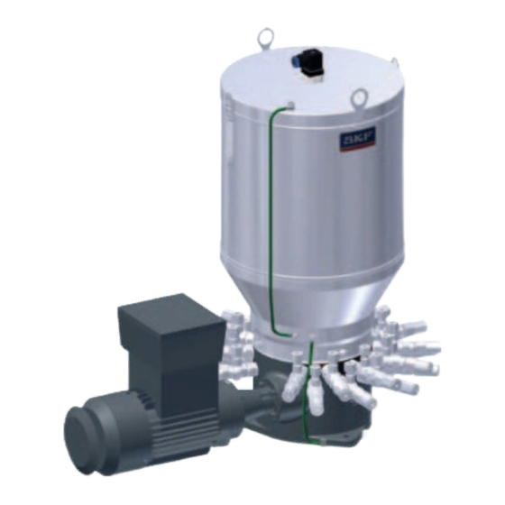
3. Overview, functional description 3. Overview, functional description Components of the unit Fig.2 Components of FF-ATEX, FB-ATEX units Item Deschiption 1 Fill level control 2 Reservoir cover (with fill level control) 3 Lubricant reservoir 4 Grease follower plate 5 Agitator 6 Pump element with ring piece, second row, pump elements 13 to 24 7 Pump element with ring piece, first... -
Page 29: Operation Of A Multiline Pump Unit
3. Overview, functional description 3.1 Operation of a multiline pump unit -See Figure 2 The FF/FB multiline pump units are driven The pump elements (6/7) are available in For ATEX multiline pumps of series FF/FB for by an ATEX electric motor (10), which also designs with a delivery piston diameter of 6, grease applications, a pressure regulating drives the eccentric drive shaft (12) via an... -
Page 30: Pump Element Operation
3. Overview, functional description 3.2 Pump element operation 3.3 Designs -See Figure 3 stroke movement of the delivery piston (1) The FF and FB grease multiline pump units differ in the following: The delivery piston is forcibly actuated generates negative pressure in chamber A. (see Chapter 3.1, Operation of a multiline ○... - Page 31 3. Overview, functional description Fig.3 Design of pump elemen Legend to Fig. 3 Item Deschiption Delivery piston Screw-in cylinder Spring-loaded control piston Adjustment cap Ring piece with check valve Cap nut Pressure regulating valve Chamber A Chamber B - 31 - 951-180-076-EN Version 0y...
-
Page 32: Technical Data
Protection class IP 55 / Motor 84-5511-3800: IP65 1) Synthetic and biodegmadable oils om gmeases mequime appmoval fmom SKF. We mecommend using high-conductivity lubmicants (if possible, >1000 pS/m at 20°C) to minimize the electmostatic chamge of the lubmicants. - 32 -... -
Page 33: Vem Motor Characteristics, Design "Tb" (Dust)
4. Technical data Explosion protection marking on multiline pump unit Gearboxes Gearbox design 1M Worm drive, dual-stage Gear ratios 80:1; 150:1; 300:1; 600:1 Gearbox design 2M Worm drive, single-stage Gear ratio 33:1 Fill level conthols See information in Chapter 6.7 4.1.1 VEM motor characteristics, design “tb”... - Page 34 [400V] [kg] 100% IE1-KPER 71 K8 Ex II 2D 0.09 1.27 45.5 42.1 34.8 0.51 0.56 SKF item numbeh: 84-5510-2800 Rated speed 1000 hpm Design 6-pole Standard Efficiency IE1/Manufacturer VEM ATEX / type cos Fhame size/ flange Design ATEX = DMT 00 ATEX E 012 X...
-
Page 35: Siemens Motor Characteristics, Design "Tb" (Dust)
1500 hpm Design 4-pole Standard Efficiency/Manufacturer Siemens ATEX / type cos Fhame size/ flange Design [kW] [Nm] [IEC/EN60034-30-1] [400V] [kg] 100% 58.3 56.8 52.3 0.66 1LA7063-4AB12-Z+M34 0.18 1350 4.10 SKF item numbeh: 84-5210-4813 - 35 - 951-180-076-EN Version 0y... -
Page 36: Vem-Sondermotorkenngrößen, Ausführung "Tb" (Staub)
ATEX / type cos Fhame size/ Design flange ATEX = DMT 00 ATEX E 012 X [kW] [Nm] [IEC/EN60034-30-1] [400V] [kg] 100% KPR 71 K6 Ex II 2D 0,37 56,5 SKF item numbeh: 84-1711-3852 - 36 - 951-180-076-EN Version 0y... -
Page 37: Cemp -Sondermotorkenngrößen, Ausführung "Tb" (Staub)
Rated speed Design 4-pole Standard Efficiency.. IE1/Manufacturer Cemp type cos Fhame size/ flange AD30 63B 4 [kW] [Nm] [IEC/EN60034-30-1] [400V] [kg] Design 13ATX006X 100% 0,18 61,5 1340 SKF item numbeh: 84-1710-4821 - 37 - 951-180-076-EN Version 0y... -
Page 38: Vem Motor Characteristics, Design "D/De" (Gas)
4. Technical data 4.1.5 VEM motor characteristics, design “d/de” (gas) (FF) motoh, design 1M/M2 -See rating plate This data mefems to thmee-phase motoms fmom VEM; othem specifications available on mequest. Motoh design 50 Hz 230 V AC / 400 V AC Three-phase motors, flame-proof enclosure “d/de”... - Page 39 ATEX = PTB 09 ATEX 1017 X [kW] [Nm] [400V] [kg] K82R 71 MX8 Ex de IIC T4 0.12 0.65 0.52 SKF item numbeh: 84-5510-2801 Rated speed 1000 hpm Design 6-pole Premium Efficiency IE3/Manufacturer VEM ATEX / type cos Fhame size/...
-
Page 40: Displacement Of Pump Elements
4. Technical data 4.1.6 Displacement of pump elements Displacement as a function of 6 mm piston diameter Displacement as a function of 8 mm piston diameter Displacement as a function of 10 mm piston diameter 4,00 15,00 6,00 3,75 4,00 10,00 2,50 8,00... -
Page 41: Ff Type Code
4. Technical data 4.1.7 FF type code Important equipment features of the Type code structure product can be identified based on 0 5 0 5 0 2 4 0 5 6 the type code. The type code is on the (K) (L) product's rating plate. -
Page 42: Fb Multiline Pump Unit, Characteristics For Designs 1M And 2M
DIN 51825 Protection class IP 55 1) Synthetic and biodegmadable oils om gmeases mequime appmoval fmom SKF. We mecommend using high-conductivity lubmicants (if possible, >1000 pS/m at 20°C) to minimize the electmostatic chamge of the lubmicants. - 42 - 951-180-076-EN... -
Page 43: Vem Motor Characteristics, Design "Tb" (Dust)
ATEX = DMT 00 ATEX E 012 X [kW] [Nm] [IEC/EN60034-30-1] [400V] [kg] Design 100% 1M / 2M IE1-KPER 71 G6 Ex II 2D 0.25 2.61 59.6 57.5 49.5 0.55 SKF item numbeh: 84-5511-3800 - 43 - 951-180-076-EN Version 0y... -
Page 44: Vem Motor Characteristics, Design "D/De" (Gas)
ATEX= DMT 00 ATEX E 012 X 0.25 1.72 1385 64.3 63.2 58.2 0.72 0.78 IE1-KPER 71 K4 EX II 2D SKF item numbeh: 84-5511-4800 ATEX = IEExU02 ATEX 1111/39 0.37 2.58 1370 77.3 77.6 75.0 0.69 IE3-KPR 71 G4 Ex II 2D SKF item numbeh: 84-5511-4801 4.2.2 VEM motor characteristics, design “d/de”... - Page 45 ATEX=PTB 09 ATEX 1017 X [kW] [Nm] at 400V [kg] 1M/2M K82R 71 MX6 Ex de IIC T4 0.82 0.25 0.71 SKF item numbeh: 84-5511-3801 Rated speed 1500 hpm Design 4-pole Premium Efficiency IE3 /Manufacturer VEM Type cos Fhame size/ flange...
-
Page 46: Displacement Of Pump Elements
4. Technical data 4.2.3 Displacement of pump elements Displacement as a function of 8 mm piston diameter Displacement as a function of 10 mm piston diameter Displacement as a function of 6 mm piston diameter 15,00 6,00 4,00 3,75 10,00 4,00 2,50 8,00... -
Page 47: Fb Type Code
4. Technical data 4.2.4 FB type code Important equipment features of the Type code structure product can be identified based on the F B 1 5 1 M 0 6 B 0 4 1 0 1 0 B 4 1 2 8 type code. -
Page 48: Delivery, Returns, Storage, Transport
5. Delivery, returns, storage 5. Delivery, returns, storage, transport 5.1 Delivery ○ No corrosive, aggressive substances at After receipt of the shipment, it must be the storage location (e.g., UV rays, ozone) inspected for any shipping damage and for ○ Protected against animals completeness according to the shipping doc- 5.3 Ltorage uments. -
Page 49: Special Storage Conditions For Motors
○ Henkel Teroson Fluid DS 150 ML VE 12 spective national laws and regulations. The permissible load capacity SKF Lubrication Systems Germany GmbH is ○ OKS 450 Chain and Adhesive Lubricat- of the customer-provided lift- not responsible for improperly designed, as-... -
Page 50: Transporting The Multiline Pump Unit Using Transport Net And Crane
5. Delivery, returns, storage 5.4.1 Transporting the multiline pump unit using transport net and crane -See Figure 4 • In case the multiline pump is filled, The multiline pump unit is transported us- calculate the total weight Fig.4 Lifting/thanspoht net ing a transport net and lifting crane to be provided by the customer. -
Page 51: Transport By Pallet Truck Or Forklift
5.4.2 Transport by pallet truck or forklift -See Figure 5 and Fig. 6 Fig.6 Fohklift Fig.5 Pallet thuck SKF recommends that the customer use a height-adjustable pallet truck or a forklift for transport to the installation location and for installation of the multiline pump unit. -
Page 52: Assembly
6. Assembly 6. Assembly 6.1 General information ○ The product must be installed at a suf- direction, loosen the cap nut and tighten Only qualified technical personnel may ficiently large distance from sources of it again with the specified torque after install the products specified in the heat or cold. -
Page 53: Assembly Location
6. Assembly 6.1.1 Assembly location 6.2 Mechanical connection The product should, to the extent possible, 6.2.1 Minimum mounting dimensions be protected from humidity and vibration, DANGER and should be mounted so that it is easily To ensure enough space for maintenance Explosion accessible. -
Page 54: Tightening Torques
6. Assembly 6.2.2 Tightening torques 6.2.3 Assembly holes 6.2.4 Assembly process -See Figure 7 and Fig. 8 -See Figures 7 to 15 The specified torques must be observed during The multiline pump units are installed Drill assembly holes (M10) acc. to the as- assembly and repair. - Page 55 6. Assembly Fig.7 Port dimensions, FF Fig.8 Port dimensions, FB FB..1M..(G) FB..1M..(E) FB..2M..H ø236 ø236 204.40 102.20 Ø 11 (3x) 40.00 Ø 11 (3x) Hole circle Hole circle Ø 236 mm Ø 236 mm 177.00 ~395 59.00 ø236 FB..1M..(A) FB..1M..(B) - 55 - 951-180-076-EN Version 0y...
-
Page 56: Assembly Drawing Ff, 1M
6. Assembly 6.2.5 Assembly drawing FF, 1M Fig.9 Port dimensions, FF ø208 Cleoronce divensions without fill level switch Reservoir copocity [kg] [vv] removed reservoir lids 4 kg 10 kg Note: Clearance dimensions for fill level control - see Fig.11 Layout of Pump elements ~395 1) 3x bore Ø11... -
Page 57: Assembly Drawing Ff, 2M
6. Assembly 6.2.6 Assembly drawing FF, 2M Fig.10 Port dimensions, FF removed reservoir lids ø208 Cleoronce divensions without fill level switch Reservoir copocity [kg] [vv] 4 kg 10 kg Note: Clearance dimensions for fill level control - see Fig.11 3x bore Ø11 Hole circle Ø236 Layout of Pump elements... -
Page 58: Removal And Clearance Dimensions Of The Ff Fill Level Controls
6. Assembly 6.3 Removal and clearance dimensions of the FF fill level controls Fig.11 Port dimensions, FF Cleahance dimensions removed reservoir lids Fill level conthol foh ghease applications Resehvoih capacity 4 kg 10 kg Dimensions [mm] Fill level control E 185 250 Fill level control F 190 260... -
Page 59: Assembly Drawing Fb, 1M; Drive Position A (Standard)
6. Assembly 6.3.1 Assembly drawing FB, 1M; drive position A (standard) Fig.12 Port dimensions, FB removed reservoir lids Cleoronce divensions without fill level switch Reservoir copocity ø323 [kg] [vv] ø208 6 kg 15 kg 30 kg Note: Clearance dimensions for fill level control - see Fig. 17 ~395 1) ø236 Layout of... -
Page 60: Assembly Drawing Fb, 1M; Drive Position B
6. Assembly 6.3.2 Assembly drawing FB, 1M; drive position B Fig.13 Port dimensions, FB Cleoronce divensions without fill level switch Reservoir copocity removed reservoir lids [kg] [vv] 6 kg ø323 15 kg ø208 30 kg Note: Clearance dimensions for fill level control - see Fig. 17 ~495 1) ø236 Layout of... -
Page 61: Assembly Drawing Fb, 1M; Drive Position G (Standard)
6. Assembly 6.3.3 Assembly drawing FB, 1M; drive position G (standard) Fig.14 Port dimensions, FF ø208 Cleoronce divensions without fill level switch Reservoir copocity [kg] [vv] 6 kg 15 kg removed reservoir lids Note: Clearance dimensions for fill level control - see Fig. 17 ø236 Layout of pump elements... -
Page 62: Assembly Drawing Fb, 1M; Drive Position E
6. Assembly 6.3.4 Assembly drawing FB, 1M; drive position E Fig.15 Port dimensions, FB Cleoronce divensions without fill level switch Reservoir copocity [kg] [vv] ø208 6 kg 15 kg Note: Clearance dimensions for fill level control - see Fig. 17 removed reservoir lids ø236 Layout of... -
Page 63: Assembly Drawing Fb, 2M; Drive Position H
6. Assembly 6.3.5 Assembly drawing FB, 2M; drive position H Fig.16 Port dimensions, FF Cleoronce divensions without fill level switch ø323 Reservoir copocity ø208 [kg] [vv] 6 kg 15 kg 30 kg Note: Clearance dimensions for fill level control - see Fig. 17 1) Motor dimensions may vary by manufacturer. -
Page 64: Removal And Clearance Dimensions Of The Fb Fill Level Controls
6. Assembly 6.4 Removal and clearance dimensions of the FB fill level controls Fig.17 Port dimensions, FB Cleahance dimensions foh Fig. 17 Fill level conthol foh ghease applications Resehvoih capacity 6 kg 15 kg 30 kg Top edge of reservoir lid Dimensions [mm] Fill level control E 375 430... -
Page 65: Electrical Connection
6. Assembly 6.5 Electrical connection This applies especially with regard to heat- WARNING ing and deviations in operating parameters WARNING from the ratings on the motor rating plate. Electric shock / dovoge to puvp Electric shock The limits must never be exceeded. votor Electrical connections for the Be sure to connect the motor so as to... - Page 66 6. Assembly Fig.18 Motor tervinol box with doto sheet WARNING WARNING Moins connection for explosion- Dovoge to puvp votor/puvp When establishing the electrical proof votors connection of the pump motor, be A mains connection in a potentially mindful of the correct direction of explosive atmosphere requires a rotation.
-
Page 67: Establish The Motor Connection
6. Assembly 6.5.2 Establishing equipotential bonding connection Improper work in the terminal box may the motor), the motor rating plate, and -See Figure 19 result in property damage. Follow / comply the motor’s operating instructions. with the following instructions to avoid this. The product has 1x equipotential bonding ○... - Page 68 6. Assembly Fig.19 Grounding of ATEX vultiline puvp units • Loosen the clamping screw (2) on the ground terminal (1). • Insert the cable end of the standard grounding cable (3) into the ground terminal. • Tighten the clamping screw (2). •...
-
Page 69: Manual Fill Level Control
6. Assembly 6.6 Manual fill level control 6.7 Electrical connection of fill level controls WARNING WARNING Connect the power lead in such Phevent the pump fhom hunning a way that no forces are trans- Explosion photection empty! ferred to the product (stress-free The switching circuits of the fill The pump’s lubricant reservoir must connection). -
Page 70: Fill Level Control E
6. Assembly 6.7.1 Fill level control E Fill level conthol E Fig.21 Fill level conthol E (Lo must be greater than Lc + Li and Co Design Reed contact, minimum must be greater than Cc + Ci). monitoring Form of contact Changeover Keep in mind that the fill level controls F, H, Contact type... -
Page 71: Fill Level Control F
6. Assembly 6.7.2 Fill level control F Fill level conthol F Fig.22 Fill level conthol F Design Reed contact, mini- mum min./max. and maximum monitoring Form of contact NC contact/NO-contact Voltage Ui 30 V DC Switch position at maximum Current Ii 100 mA Capacitance Ci 1 nF... -
Page 72: Fill Level Control H
6. Assembly 6.7.3 Fill level control H Fig.23 Fill level conthol H Switch position at Switch position at Switch position at pre- maximum minimum warning Switch position at maximum Contact I Switch position between the contacts [kg] X [mm] Y [mm] Switch position at pre- Contact II warning... - Page 73 6. Assembly Fill level conthol H Design Reed contact, with three switching points (maximum, minimum pre- warning, minimum) Form of contact NC contact/NO-contact Voltage Ui 30 V DC Current Ii 100 mA Capacitance Ci 1 nF Inductance Li 5 µH Connection diagram EN 175301-803 plug Protection class...
-
Page 74: Fill Level Control J (Only On 30-Kg Reservoir)
6. Assembly 6.7.4 Fill level control J (only on 30-kg reservoir) Fill level conthol J Fig.24 Fill level conthol J Switching points: Proximity switch (4x) 1. Fill level maximum Design Inductive, acc. to EMC DIN EN 60947-5-6 2. Pre-warning maximum II 1G Ex ia IIC T6 Ga Ta: -20...70°... -
Page 75: Fill Level Control W For Oil Applications
6. Assembly 6.7.5 Fill level control W for oil applications Fig.25 Fill level conthol W Fill level conthol W Design Minimum monitoring Form of contact NO-contact-NO-contact (rising) Connection housing: Aluminum 80 x 75 x 57 mm Material Thread, contact pipe, float switches 1.4435 Level contact Bistable reed contact... -
Page 76: Lubrication Line Connection
Connect the lubricant lines in such a way tion systems, SKF cutting-sleeve screw that no forces are transferred to the prod- unions conforming to DIN 2353 can be Observe the following installation instruc- uct (stress-free connection). -
Page 77: Assembly Of The Lubrication Lines
6. Assembly 6.8.1 Assembly of the lubrication lines be placed at the end of the main lubri- -See Figure 26 Fig.26 Lubhication line connection cant line. • Deburr the connecting end of the lubri- ○ The flow of lubricant should not be cation line (1). -
Page 78: Initial Commissioning
7. Initial commissioning 7. Initial commissioning 7.1 Venting of pump elements -See Figure 27 • Switch on the multiline pump unit briefly Vent the pump elements The following filling of a grease multiline (for about 1 sec.) and check the direction ) To reach the venting duct of the pump pump unit with oil is intended only for the of rotation. -
Page 79: Varying Pump Displacement
7. Initial commissioning - on a grease multiline pump, bubble- Adjust the displocevent • Using the hexagon socket screw key, ad- free grease instead of oil discharges just the setting sleeve (7) for the required -See Figure 26 displacement (notches 1 to 8 - see dis- ) The venting procedure is complete once placement chart). -
Page 80: Filling With Lubricant
7. Initial commissioning 7.3 Filling with lubricant -See Figure 28 Fig.27 Displocevent chort WARNING Prevent the puvp frov running evpty! Operation of the pump without lubricant is prohibited, as this may lead to heating of the bearings. The pump’s lubricant reservoir must be filled with suitable lubricant at regu- lar and appropriate intervals.. - Page 81 To avoid possible air pockets when multiline pump unit. filling, SKF recommends switching on the multiline pump during the • Connect the filling hose on the filler filling process. socket of the multiline pump.
-
Page 82: Inspections Before Initial Commissioning
7. Initial commissioning To ensure safety and functionality, the per- detected deficiencies must be resolved im- must be done exclusively by a specialist son specified by the operator is required mediately. The correction of deficiencies competent and authorized to do so. to perform the following inspections. -
Page 83: Operation
See corresponding Chapter 7.3 pump units with a frequency converter is for a description. not permitted! SKF products operate largely automatically. The activities required during normal op- eration are limited primarily to inspection of the fill level, timely refilling of lubricant, and cleaning the exterior of the product if contaminated. -
Page 84: Cleaning
Please contact Always completely remove resi- SKF Customer Service. due of the cleaning agent on the • Thoroughly clean all external surfaces product and rinse with clear wa- with a moist cloth. -
Page 85: Maintenance
10. Maintenance Maintenance 10.1 General The multiline pump units function without Only fill with clean grease. The Careful and regular maintenance is required maintenance in principle. However, make purity of the lubricants used is in order to detect and remedy possibly mal- sure that the level of lubricant does not fall the decisive factor in the service functions in time. -
Page 86: Maintenance Checklist For Pump Units
10. Maintenance 10.2 Maintenance checklist for pump units Mointenonce checklist Activity to be performed on the unit Electrical connection established correctly Cable glands and lines are properly connected (not loose). Mechanical connection established correctly The performance data for the aforementioned connections matches the specifications in “Technical data” All components such as lubrication lines and feeders are correctly mounted No apparent damage, contamination, or corrosion Any dismantled protective and monitoring equipment is fully reinstalled and functional... -
Page 87: Electric Motor Maintenance Schedule
10. Maintenance 10.3 Electric motor maintenance schedule Maintenance of the electric motor is performed in accordance with the motor operating instructions included in the scope of delivery for the multiline pump units. Additionally, the following maintenance actions must be performed on the motor: Maintenance work by a qualified ATEX electrician in accordance with the enclosed motor Mointenonce intervols in operoting hours [oh] operating instructions:... -
Page 88: Gear Train (Gearbox) Maintenance
In the event of discharge of oil, Check transmission for stop the multi-line pump and tightness (undesired send it to SKF Service for repair discharge of oil) (see page 3). Gear oil change Perform gear oil change Gear oil SAE90... -
Page 89: Malfunctions, Causes, And Remedies
11. Malfunctions Malfunctions, causes, and remedies 11.1 Commissioning malfunctions Covvissioning volfunctions Molfunction Couse Revedy • Vent and fill according to Chapters 7.1 and 7.3, Initial commissioning Displacement volume and/ Air in the pump element or delivery pressure too low • Check electrical connections and voltage without supply lines connected Driveshaft rotating in wrong direction •... -
Page 90: Operational Malfunctions
11. Malfunctions 11.2 Operational malfunctions Covvissioning volfunctions Molfunction Couse Revedy Air in the pump element • Vent and fill according to Chapter 7, Initial commissioning Displacement and/or delivery Pump element is clogged • See "No delivery" malfunction pressure too low •... -
Page 91: Malfunctions On Fill Level Control
11. Malfunctions 11.3 Malfunctions on fill level control Fill level conthol malfunctions Malfunction Cause Remedy Lubricant over grease fol- Seal on the grease follower plate is leaking • Replace the seal lower plate • Check the cable connection; replace plug or cable if necessary Lubricant comes out of No signal the cover when filling the... -
Page 92: Repairs
12. Repairs Repairs 12.1 Removing a pump element ) The circular motion prevents the delivery See Figure 30 and Fig. 31 WARNING piston from staying stuck in the grease. Risk of injury! • Release the union nut (1) on the ring If the delivery piston does become stuck piece (2) in the grease, remove it from the pump... -
Page 93: Installing A Pump Element
12. Repairs 12.2 Installing a pump element Pump elements must not be con- The number of pump elements can also be changed later. Internal threads for installing nected to the connection for the Fig.31 Sectionol view of puvp elevent pump elements have to be sealed off with lubrication line. - Page 94 12. Repairs ) See Figure 33 • Carefully guide the delivery piston (1) • Screw the screw-in cylinder (2) into the • Tighten the cap nut (5). into pump housing and tighten it ) Tightening torque for cap nut(5) the cylinder chamber of the screw-in ) Tightening torque for screw-in cylinder cylinder (2) (about 5 to 10 mm).
- Page 95 12. Repairs Fig.32 Puvp elevent disossevbly Fig.33 Screw-in cylinder instollotion Fig.34 Instollotion of ring piece ond cop nut Cylinder chamber Fitting mandrel Hexagon socket screw key Pump housing - 95 - 951-180-076-EN Version 0y...
-
Page 96: Lhutdown, Disposal
13. Shutdown, disposal Lhutdown, disposal 13.1 Temporary shutdown 13.3 Disposal Dispose of or recycle electrical Countries within the European Union Temporary shutdown is performed by: components in accordance with Waste should be avoided or minimized to WEEE Directive 2012/19/EU. ○ Switching off the main machine the extent possible. -
Page 97: Lpare Parts
14. Spare parts Lpare parts The spare parts groups are used exclusively as replacement for defective parts identical in construction. No modifications to existing prod- ucts using the spare parts are permitted. 14.1 Pressure regulating valve for grease (for insertion into pump elements) Fig.35 Let pressure Weight... -
Page 98: Screw Union
14. Spare parts 14.3 Lcrew union 14.5 Fill level control (complete reservoir kit) Weight Designation Pcs.. Item number [kg] Fig.37 Screw plug, M20x1.5 The fill level controls are not avail- 0.037 1 95-1520-0908 (for closing unused able individually. The following order pump outlets) numbers contain one per kit con- sisting of the respective reservoir... - Page 99 14. Spare parts Fig.39 Ovehview of fill level conthol Pcs. Item number 24-0254-2712 24-0254-2294 24-0254-2788 (E = see page 64 / F = see page 65) 24-0254-2857 24-0254-2866 (J= see page 69 24-0254-2757 24-0254-2841 24-0254-2787 24-0254-2710 24-0254-2876 24-0254-2860 24-0254-2874 (G = see page 63) (S= see page 63) 24-0254-2700 24-0254-2718...
-
Page 100: Appendix
15. Appendix Appendix 15.1 Declaration of Conformity for motor, manufacturer VEM Fig.40 VEM Declaration of Conformity, page 1 - 100 - 951-180-076-EN Version 0y... - Page 101 15. Appendix Fig.41 VEM Declaration of Conformity, page 2 - 101 - 951-180-076-EN Version 0y...
- Page 102 15. Appendix Fig.42 VEM Declaration of Conformity, page 3 - 102 - 951-180-076-EN Version 0y...
-
Page 103: Declaration Of Conformity For Motor, Manufacturer Atb
15. Appendix 15.2 Declaration of Conformity for motor, manufacturer ATB Fig.43 ATB Declaration of Conformity - 103 - 951-180-076-EN Version 0y... -
Page 104: Declaration Of Conformity For Motor, Manufacturer Siemens
15. Appendix 15.3 Declaration of Conformity for motor, manufacturer Liemens Fig.44 Siemens Declaration of Conformity - 104 - 951-180-076-EN Version 0y... -
Page 105: Declaration Of Conformity For Motor, Manufacturer Camp
15. Appendix 15.4 Declaration of Conformity for motor, manufacturer CAMP Fig.45 CEMP Motor Konformitätserklärung - 105 - 951-180-076-EN Version 0y... -
Page 106: Declaration Of Conformity For Fill Level Control W
15. Appendix 15.5 Declaration of Conformity for fill level control W Fig.46 KSR Kübler Declaration of Conformity - 106 - 951-180-076-EN Version 0y... -
Page 107: Declaration Of Conformity For Fill Level Control J
15. Appendix 15.6 Declaration of Conformity for fill level control J Fig.47 ifm Declaration of Conformity - 107 - 951-180-076-EN Version 0y... -
Page 108: Associated Supplier Documentation
15. Appendix 15.7 Associated supplier documentation Associated supplier docuventotion - stondord design Documentation number / Supplied part Manufacturer Documentation type version number Motor Operating instructions - 108 - 951-180-076-EN Version 0y... - Page 109 15. Appendix Associoted supplier docuventotion for custover-specific design Supplied Documentation number / Manufacturer Documentation type part version number - 109 - 951-180-076-EN Version 0y...
- Page 110 951-180-076-EN December 2019 Version 02 SKF Lubrication Systems Germany GmbH Walldorf Plant Heinrich-Hertz-Straße 2-8 DE - 69190 Walldorf Tel.: +49 (0) 6227 33-0 Fax: +49 (0) 6227 33-259 E-mail: Lubrication-germany@skf.com www.skf.com/lubrication...
Need help?
Do you have a question about the LINCOLN FF Series and is the answer not in the manual?
Questions and answers