
Related Manuals for SKF ST-1240-GRAPH


Summary of Contents for SKF ST-1240-GRAPH
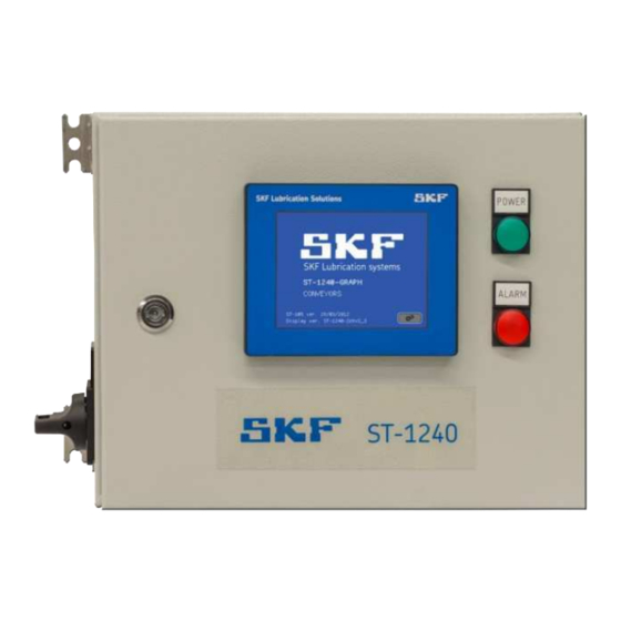
- Page 1 ST-1240-GRAPH CONTROL CENTRE FOR CENTRALISED LUBRICATION SYSTEM Date: 16/9/2022 Document no: ST-1240-GRAPH Version: 1C Read this manual before installing or commissioning the product and keep it at hand for later reference.
- Page 2 Technical documentation has been drawn up in accordance with Part B of Annex VII. The manufacturer undertakes to deliver the technical documentation to national authorities in electronic format when so requested. The company authorised to compile the technical documents is SKF (U.K.) Limited, 2 Canada Close, Banbury, Oxfordshire, OX16 2RT, GBR. Description: Control centre for controlling various lubrication systems.
-
Page 3: Masthead
The instructions contain no statements regarding the warranty or liability for defects. That information can be found in our General Terms of Payment and Delivery. Training We conduct detailed training in order to enable maximum safety and efficiency. We recommend taking advantage of this training. For further information, contact your authorised SKF dealer or the manufacturer. -
Page 4: Table Of Contents
Transport, installation, maintenance, malfunctions, repairs, shutdown for maintenance and disposal ......14 First start-up, daily start-up ..............................14 Cleaning ..................................... 14 Residual risks ..................................15 2. ST-1240-GRAPH CONTROL CENTRE ............................ 16 General description ................................16 3. TECHNICAL SPECIFICATIONS ............................... 18 4. MAIN COMPONENTS ................................19 Main parts .................................... - Page 5 7.4.2 Parameters to be set ..............................34 7.4.3 Changing set values ..............................35 Configuration settings of the lubrication channel ......................... 35 Other settings ..................................37 Entering password ................................38 8. REMOTE CONTROL INTERFACE - WEB GATE........................39 Setting up the remote control............................... 39 Launching the Web Gate ..............................
-
Page 6: Safety Alerts, Visual Presentation, And Layout
Safety alerts, visual presentation, and layout While reading these instructions, you will encounter various symbols, illustrations, and text layouts intended to help you navigate and understand the instructions. Their meaning is explained below. Safety alerts: Activities that present specific hazards (to life and limb or possible damage to property) are indicated with safety alerts. Always be sure to follow the instructions given in the safety alerts. - Page 7 Symbol Meaning ¯ Instruction step ñ List item Conditions which must be met before the activities ð described in the title clause can be completed ö Related factors, causes or consequences Conversion factors length 1 mm = 0.03937 in. area 1 cm²...
- Page 8 Abbreviations approx. approximately °C degrees Celsius °F degrees Fahrenheit i.e. in other words; that is Kelvin ounce etc. et cetera Newton fl. oz. fluid ounce poss. possibly hour inch incl. including second pounds per square inch min. minimum sq.in. square inch max.
-
Page 9: Safety Instructions
" Unauthorised changes may have unexpected effects on the safety and performance of the product, which is why making such changes is prohibited. Only original SKF spare parts and SKF accessories may be used. " Any unclear points regarding proper condition or correct assembly/operation must be clarified. Operation is prohibited until issues have been clarified. -
Page 10: General Electrical Safety Instructions
" Never use parts of the centralised lubrication system or of the machine as standing or climbing aids. Intended use SKF control centre is used for controlling various lubrication systems in accordance with the specifications, technical data and limits stated in these instructions. -
Page 11: Provision Of Personal Protective Equipment
Foreseeable misuse Any use differing from that stated in these instructions is strictly prohibited, particularly the following: " use outside the indicated temperature range, see Technical specifications ST-1240-GRAPH " use in areas with aggressive or corrosive materials (e.g. high ozone pollution);... -
Page 12: Notes On The Type Plate
Notes on the type plate The type plate provides important data such as the type designation, order number, and sometimes regulatory characteristics. To avoid loss of this data in case the type plate becomes illegible, it should be entered in the manual. Figure 2 type plate Notes concerning CE marking... -
Page 13: Emergency Shutdown
Emergency shutdown This is done by a course of action to be defined by the operator. Assembly, maintenance, fault, repair Prior to the start of this work, all relevant persons must be notified of it. At a minimum, the following safety measures must be taken before any work is done: "... -
Page 14: Transport, Installation, Maintenance, Malfunctions, Repairs, Shutdown For Maintenance And Disposal
Transport, installation, maintenance, malfunctions, repairs, shutdown for maintenance and disposal " All relevant persons must be informed of the activity prior to starting any work. Observe safe operating measures and work instructions. " Transport the products with suitable transportation and hoisting equipment using suitable work methods. "... -
Page 15: Residual Risks
Residual risks Residual risk Prevention/remedy Lifecycle stage: Installation / start-up / operation / setting and retrofitting " Check the supply cable before connecting power supply to the Electrical shock caused by a faulty or incorrectly connected device. power cable " Connect all wires correctly. Torn/broken wires, when "... -
Page 16: St-1240-Graph Control Centre
ST-1240-GRAPH is a microprocessor-based control centre for SKF Dual-line (DuoFlex), SKF Single-line (MonoFlex) and SKF Progressive (ProFlex) lubrication systems. The control centre can be used for controlling two separate lubrication channels or systems. ST-1240-GRAPH controls lubrication in accordance with the given settings and triggers an alarm for any possible malfunctions. -
Page 18: Technical Specifications
3. TECHNICAL SPECIFICATIONS 0&+50 °C Operation temperature +32&+122 °F Operating voltage 115 V / 230 VAC, automatic range selection Operating voltage range 93 to 132 V AC; 186 to 264 V AC Operating voltage frequency 47 to 63 Hz Power consumption 5.4 A/115 V AC, 2.2 A/230 V AC Fuse Circuit breaker, 6 A... -
Page 19: Main Components
4. MAIN COMPONENTS Main parts Main parts of the ST-1240-GRAPH control centre are: main switch (pos. 7) on the side of the casing indicator lamps: a green indicator lamp for power (pos. 5) and a red indicator lamp for alarm (pos. 6) on the casing cover HMI control panel (pos. - Page 20 Connector X0 Signal Input voltage 115VAC/230VAC Input voltage 115VAC/230VAC Protective ground Connector XA Signal 4&20 mA or contact input Pressure transmitter/switch channel 1 line 1 3 Pressure transmitter/switch channel 1 line 1 + 4&20 mA or contact input Pressure transmitter/switch channel 1 line 2 - Pressure transmitter/switch channel 1 line 2 +...
- Page 21 4&20 mA or contact input Pressure transmitter/switch channel 2 line 2 - Pressure transmitter/switch channel 2 line 2 + Low limit channel 2 (Master / LL1) (+) contact input 0 V (Master / LL1) (-) Channel 2 line 1 control or channel 1 24V/ 2A shut-off valve control Channel 2 line 2 control or channel 2...
-
Page 22: Pressure Transmitter/Switch Inputs
Channel 1 interlocking, relay coil + input 24V/40mA *) Channel 1 interlocking, relay coil - Channel 2 interlocking, relay coil + input 24V/40mA *) Channel 2 interlocking, relay coil - Alarm contact output (C) max. 230V/1A Alarm contact output (NO), open in alarm mode Alarm contact output (NC), closed in alarm mode... -
Page 23: Interlocking Inputs 3 External Signals
(Slave) barrel in case where the first (Master) barrel becomes empty the secondary (slave) barrel will be taken into use automatically by the ST-1240-GRAPH control centre. If the pump configuration is: 1 pumping centre, Dualset, the channels share a doubled pump. The master pump is connected to the master pump control output of channel 1 and the slave pump is connected to the master pump control output of channel 2. -
Page 24: Other Properties
5. OTHER PROPERTIES Collection of lubrication history and analysis The ST-1240-GRAPH saves the centre9s lubrication events into a battery-backed-up memory. The lubrication history data can be read and analysed with the PC software Online1440. The ST-1240-GRAPH support the Windows software Online 1440, which is designed for controlling, monitoring and analysing lubrication systems. -
Page 25: Dimensions
Dimensions... -
Page 26: Spare Parts
6. SPARE PARTS Circuit board ST105-GRAPH 4 12380050 Connector board CB-105 12500410 Power supply unit DRA-240 13500332 User interface HMI Panel 12500415 LED indicator, green 10544185 Led indicator, red 10544180... -
Page 27: St-1240-Graph User Interface
7. ST-1240-GRAPH USER INTERFACE General description The user interface of the control centre ST-1240-GRAPH is a colour touch screen panel. The user interface is used for programming lubrication, acknowledging alarms and monitoring lubrication events. Main components The GRAPH user interface includes a touch screen, which is divided into a lubrication channel specific status display and parameter display pages. -
Page 28: Displays
Displays 7.3.1 Start display When the ST-1240-GRAPH centre is switched on, a start page is displayed Go to the lubrication channel display by pressing the button . The status display for channel 1 opens. Lubrication centre9s name Software versions of... - Page 29 Display lines The texts in brackets are examples of display texts. NOTE! The first line indicates the selected channel: " number (CH1 = lubrication channel 1) " operation mode, see section 3.4 (DuoFlex, SG) " name (Conveyor 1) Next, the selected channel is shown: "...
- Page 30 When the operation mode of the channel is ProFlex (progressive lubrication system), the pulse amount counted from the piston detector monitoring the progressive distributor is shown instead of pressure display. The graphic presentation is scaled as percentages to the set pulse count. The bottom line shows the function buttons for the selected channel: "...
-
Page 31: Lubrication Program Phases
7.3.3 Lubrication program phases Phase code Phase description The time elapsed since the start of the previous pressurization is Interval presented in minutes. Interlocking input is in status ON. The interval calculation has been Interlocking interrupted. Closed The lubrication channel is not in operation. Pressurization time has been set to 0s. -
Page 32: User Actions On Status Display
7.3.4 User actions on status display The user can give the lubrication channel different control commands depending on the lubrication phase with the function button on the lower right-hand corner of the display. Interrupt pressurisation An ongoing pressurization can be interrupted. The button has the text Stop. In a dual-line system, the next pressurization starts on the other line. -
Page 33: Set Value Display And Changing Values
Set value display and changing values 7.4.1 General The user needs a username and password to be able to change the set values. See section: Entering the password The set values may be: " Numbers. When the set values in the blue field are pressed, number buttons are displayed. "... -
Page 34: Parameters To Be Set
7.4.2 Parameters to be set Parameter Description The number of lubrication cycles since the last reset. The counter can be reset. Lub. counter Autol.ON/ Autom ON: The lubrication channel is in automatic lubrication mode as per the set parameters. ManualON ManualON: The lubrication channel is in manual mode. -
Page 35: Changing Set Values
7.4.3 Changing set values Changing the set values is possible, if the password setting is active. See section Entering password. On this page,the password level is A. You can go to this page with the button Passwd. Press the touch screen at the value of the parameter to be changed. The display shows the value input page. Configuration settings of the lubrication channel This page shows a summary of the lubrication channel specific configuration settings that are usually set according to the lubrication system already upon delivery. - Page 36 Parameter Description Lubrication channel Operation mode codes: operation mode " SG1, MonoFlex: single-line grease lubrication system (in the picture " SG2, DuoFlex) SG2, DuoFlex: dual-line grease lubrication system " SG1E, MonoFlex: single-line grease lubrication system, pressurization maintaining operation " SG2E, DuoFlex: dual-line grease lubrication system, pressurization maintaining operation "...
-
Page 37: Other Settings
Other settings This page shows a summary of configuration settings that are not lubrication channel specific. The page can be entered from the set value display with the Comm conf button. Parameter Description Name The name of the centre, shown on the start display. The maximum length of the name is 10 characters. -
Page 38: Entering Password
Entering password A password needs to be entered when the set values for lubrication need to be changed. There are three password levels: Level A: The lubrication parameters can be changed on the set value page. The password is 1240. Level B: The settings can be changed on the configuration page. -
Page 39: Remote Control Interface - Web Gate
8. REMOTE CONTROL INTERFACE - WEB GATE Setting up the remote control HMI panel can be operated remotely only through the Internet Explorer web browser or Edge, provided that the following requirements are met: If the used web is Microsoft Edge make sure that the Edge browser is set to run in <Internet Explorer= mode. -
Page 40: Launching The Web Gate
Launching the Web Gate Enter the assigned control centre IP address to the web browser9s address bar. Following web page will show up. Web Gate 3 Homepage First, to start Monitoring interface login is required and interface can be opened in in frame or New window. Web Gate login window... - Page 41 Use the same user name and password than in the user interface. User Name A or B. Password for user A 1240 or user B: 1241 After login, the control centre can be remotely operated through the web browser. Web Gate user interface. Automatic logout will happen after 10 minutes if no any actions have been performed during the time.
-
Page 42: Remote Control Via Mobile Device
" Store the products clear of the ground or floor " Protect the products from mechanical shocks, corrosion and dust 11. CONTACT INFORMATION Oy SKF Ab P.O. Box 80 40951 MUURAME FINLAND Tel.: +358 20 7400 800 Fax: +358 20 7400 899... -
Page 43: Appendices
12. APPENDICES China RoHS Table Table 14...
Need help?
Do you have a question about the ST-1240-GRAPH and is the answer not in the manual?
Questions and answers