Table of Contents

Related Manuals for SKF GVP-S-034-6


Summary of Contents for SKF GVP-S-034-6
- Page 1 Installation and operation manual Grease injection lubrication system GVP-S-034-6 Date of issue December 2016 Form number 951-130-450-S034-6 Read manual prior to installation or use of this product. Keep manual nearby for future reference.
-
Page 2: Table Of Contents
10. Technical data ............Or an SKF Service Centre, the addresses 11. -
Page 3: Information Concerning The Ec Declaration Of Incorporation
EC Declaration of Incorporation in accordance with EC-Machinery Directive 2006/42/EC, Appendix II Part B The manufacturer SKF France SAS, 204, Bld Charles de Gaulle, B.P. 239 – 37540 St-Cyr-sur-Loire – FRANCE, declares herewith the confor- mity of the partly completed machine... -
Page 4: Safety Instructions
Other use or use beyond this purpose is considered unintended. Products of SKF must not be used in conjunction with subs- tances and mixtures classified as hazardous by the Annex I part 2-5 of the CLP regulation (EC 1272/2008), and identified with hazard pictograms GHS01-GHS06 and GHS08. -
Page 5: Authorized Personnel
General Conditions of Sales, which are available Qualified experts are persons who have been trained, instructed, and at: www.skf.com/lubrication. familiarized with the end product into which the described product is installed. -
Page 6: Lubricants
CLP regulation (EC 1272/2008), and identified with hazard picto- nents for the conveyance of the selected lubricant and to plan grams GHS01-GHS06 and GHS08, can only be used to feed the SKF and design their centralized lubrication system. centralized lubrication systems, transported or distributed by these systems after consultation with SKF and obtaining written permission. -
Page 7: Lubricants And The Environment
Leaking centralized lubrication systems or components of the lubri- CAUTION! cation equipment are a source of danger in relation to slip hazard Different lubricants must not be mixed together. Doing so can and the risk of injury. These dangers can cause physical injury to per- cause damage and require extensive cleaning of the products/ sons or damage to other material assets. -
Page 8: Construction And Operation
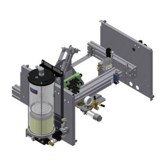
8 kg capacity. The reservoir is equipped with a follower plate and a min., warning and max. level switch. • An air treatment unit for the pneumatic air feed, with a regula- tor-filter and a manometer Fig. 1 234,81 862,31 1108 Dimensions GVP-S-034-6 dimensions in mm... -
Page 9: Function
3.2 Function The function principle of the grease injection system for the lubri- cation of conveyor chains is more or less the same for all systems († fig. 2). However some models differ from others by the type of lubrication points, the number of injection heads, etc. - Page 10 EVE2 4-20 Rollers EVE1 Pins Schematic diagram:GVP-S-034-6D and -6G E - Control assembly Schematic diagram: GVP-S-034-6 Solenoid valve 5/2, pick-up and return A - Pumping unit Solenoid valve 5/2, injection control Pressure regulating valve Air pressure gauge PVP.3 pump Lubricant pressure gauge...
-
Page 11: Installation Instructions
4. Installation instructions CAUTION! It is necessary to properly secure the GVP lubrication system on its support to prevent any accidental system fall. A system fall The product described in the mounting instructions may only be ins- may damage it or cause material damage and can also injure the talled, operated, maintained, and repaired by qualified experts. -
Page 12: Pneumatic Connection
4.2 Pneumatic connection Fig. 5 The lubrication system must be connected to the compressed air network. The compressed air quality must comply with purity class 5 defined by DIN ISO 8573-1: • Maximum particle size: 40 μm • Maximum particle density: 10 mg/m • Dew point: 7 °C • Maximum water content : 7,800 mg/m • Maximum residual oil content: 25 mg/m... -
Page 13: Electric Connection
NOTE For the product-specific electric data see the relevant documen- tation. If you do not have access to this documentation, you can request it directly from SKF. WARNING! Only qualified, instructed specialists who are authorized by the operator may install the electrical connections for the lubrication unit. -
Page 14: Mechanical Adjustments
4.5 Mechanical adjustments • Loosen the four fastening screws from the flanges († pos. A fig. 8). The position of the lubrication system must be mechanically adjust • Loosen the counter nut († pos. B fig. 8) of the adjustment screw to optimize the lubrication process. - Page 15 4.5.2 Pick-up system Fig. 9 Roller pick-up system The lubrication unit has two pick-up systems for rollers and pins. CAUTION! Adjustments to the pick-up system must only be made when the pneumatic feed is shut off and the chain stopped. First identify the two pick-up systems and then proceed to adjustment.
-
Page 16: Transport, Delivery And Storage
• Before placing products into storage, protect uncoated metal sur- SKF products are packaged in accordance with the regulations of the faces - and drive parts and mount surfaces in particular - from recipient country and in accordance with DIN ISO 9001. Our products corrosion using long-term corrosion protection. -
Page 17: Commissioning
6 Commissioning Fig. 11 6.1 General • Before starting the lubrication unit, check that all outer connec- tions (reservoir, air supply, electric connections, etc.) have been well mounted and tightened. • Check that the lubricant feed device is drained. CAUTION! ... - Page 18 NOTE The operating manual of the AEP3 control unit is delivered with the lubrication system. If you do not have access to this docu- mentation, you can request it directly from SKF. Table 1 Detection of the lubrication points Pick-up...
-
Page 19: Modification Of The Injector Metered Volume
6.3 Modification of the injector Fig. 12 metered volume 0,5 cm 1 cm The GVP lubrication system is delivered with a fixed metered volume. It is possible to modify later this metered volume. Four different metered volumes are available: 0,33 ; 0,5 ; 0,75 or 1 cm /stroke. - Page 20 Fig. 15 CAUTION! The lubrication system GVP must be disconnected from the power supply and not under pressure when modifying the metered volume. Therefore turn off the power supply and depressurize the system. • Check the GVP unit is off and the air supply closed. • Loosen the locking nut with an open end wrench (H.19) (†...
-
Page 21: Pvp.3 Pump
6.4 PVP.3 pump 6.4.1 Filling The lubrication system is equipped with a pneumatic pump and a 8 kg lubricant reservoir. The reservoir is made of transparent Plexiglas for a visual lubricant level monitoring. It is also equipped with a level switch with three switching points: • minimal level • warning level (before the minimal level) -
Page 22: Shutdown
Lubricants must be used and disposed of in compliance with the perly fitted. rules. Instructions and local regulations must be observed when handling lubricants. The system can also be taken back by SKF for disposal if the costs are covered. Table 2 GVP system maintenance... -
Page 23: Failures
Table 3 gives an overview of possible malfunctions and their causes. tallation, maintenance, and repair work may only be carried out If you are unable to rectify the malfunction, please contact SKF Ser- by qualified experts on products that are not connected to a vice Center. -
Page 24: Technical Data
10. Technical data Table 4 Technical data GVP-S-034-6 lubrication system Air feed pressure 5 to 7 bar Injection volume 0,33 to 1 cm (factory setting 1 cm Operating temperature 5 to 45 °C Lubricant grease NLGI grade 2 Chain max. speed 10 m/min Pneumatically driven pump (PVP.3) -
Page 25: Spare Parts
11. Spare parts NOTE Only original SKF spare parts may be used. It is prohibited for the operator to make alterations to the product or to use non original spare parts and resources. Table 5 Spare part list GVP-S-034-6 Position Order No. - Page 26 Fig. 21 Spare part list GVP-S-034-6 ( 1 : 4 ) ( 1 : 4 ) Option...
- Page 28 Important information on product usage SKF and Lincoln lubrication systems or their components are not approved for use with gases, liquefied gases, pressurized gases in solution and fluids with a vapor pressure exceeding normal atmospheric pressure (1 013 mbar) by more than 0,5 bar at their maximum permissible temperature.
Need help?
Do you have a question about the GVP-S-034-6 and is the answer not in the manual?
Questions and answers