Allen-Bradley A Series Installation Instructions Manual
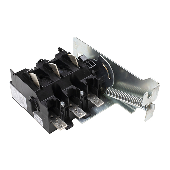
Universal disconnect switch
Hide thumbs
Also See for A Series:
- Quick start manual (38 pages) ,
- Installation instructions manual (16 pages) ,
- Troubleshooting manual (148 pages)
Table of Contents
Advertisement
Installation Instructions
Universal Disconnect Switch Installation Instructions (200A)
(Cat 1494U-D200; Series A)
WARNING: To prevent electrical shock, disconnect from power source before installing or servicing. Follow NFPA 70E requirements. Install in suitable enclosure. Keep free from
contaminants.
Installation, adjustments, putting into service, use, assembly, disassembly, and maintenance shall be carried out by suitably trained personnel in accordance with applicable code of
practice. In case of malfunction or damage, no attempts at repair should be made. The product should be returned to the manufacturer for repair. Do not dismantle the product.
WARNING: The following procedures are critical to the proper operation of the disconnect handle and switch. Failure to follow these steps can result in damage to the equipment and/or
serious injury or death to the operator.
Tools Needed: 5/16", 3/8" & 7/16" Nut Drivers, Hammer, Center Punch, File, Flat Screwdriver, Phillips Screwdriver, 7/32" Drill Bit, Needlenose Pliers, Hacksaw
Table of Contents
Rod and Cable Operated Disconnect Switch Location........................................................................................................................................................ 2
Rod Operated Switch Installation.................................................................................................................................................................................................2
Handle Installation.........................................................................................................................................................................................................................2
Cutting Connecting Rod..............................................................................................................................................................................................................3
Connecting Rod Installation.......................................................................................................................................................................................................3
Cable Operated Switch Installation.............................................................................................................................................................................................4
Handle and Cable Mechanism Installation...........................................................................................................................................................................4
Cable to Switch Mechanism Installation................................................................................................................................................................................4
Rod Operated Adjustment Procedure........................................................................................................................................................................................5
Cable Operated Adjustment Procedure.....................................................................................................................................................................................5
Enclosure without Handle Cutout................................................................................................................................................................................................6
Door Catch Bracket Installation.....................................................................................................................................................................................................6
Trailer Fuse Block Installation.........................................................................................................................................................................................................7
Fuse Clip and Fuse Installation..................................................................................................................................................................................................8
Auxiliary Contact Installation.........................................................................................................................................................................................................9
Auxiliary Contact Wire Routing.....................................................................................................................................................................................................9
Line Terminal Adapter Installation...............................................................................................................................................................................................9
Electrical Interlock Installation.......................................................................................................................................................................................................9
Protective Cover Installation........................................................................................................................................................................................................10
Bulletin 1494U Disconnect Switch Component Accessory List......................................................................................................................................11
Page
Advertisement
Table of Contents

Subscribe to Our Youtube Channel
Related Manuals for Allen-Bradley A Series


Summary of Contents for Allen-Bradley A Series
-
Page 1: Table Of Contents
Installation Instructions Universal Disconnect Switch Installation Instructions (200A) (Cat 1494U-D200; Series A) WARNING: To prevent electrical shock, disconnect from power source before installing or servicing. Follow NFPA 70E requirements. Install in suitable enclosure. Keep free from contaminants. Installation, adjustments, putting into service, use, assembly, disassembly, and maintenance shall be carried out by suitably trained personnel in accordance with applicable code of practice. -
Page 2: Rod And Cable Operated Disconnect Switch Location
Universal Disconnect Switch Installation Instructions (200A) Rod and Cable Operated Disconnect Switch Location Disconnect Switch Location and Installation A) For Rod Operated Switches, follow steps 1 - 5 below. B) For Cable Operated Switches, follow steps 3 - 5 below. IMPORTANT: When locating the 200A cable operated switch, verify that the minimum diameter for the loop of the cable between the switch mechanism and handle mechanism is not less than 6 inches. -
Page 3: Cutting Connecting Rod
Universal Disconnect Switch Installation Instructions (200A) Rod Operated Switch Installation (Cont’d) Cutting Connecting Rod Measure working depth of enclosure. Measure, mark and cut connecting rod. Remove burrs. Enclosure Mounting Working Depth Plate (Inside Flange of Enclosure to Mounting Plate) Connecting Rod Installation Verify that disconnect switch and handle are in “OFF”... -
Page 4: Cable Operated Switch Installation
Universal Disconnect Switch Installation Instructions (200A) Cable Operated Switch Installation 1494U Handle and Cable Mechanism Installation Enclosures with Right Flange Connect handle link to lever pin. Install handle nuts and hitch pin. Install defeater lever. 30-40 lb-in (3.4-4.5 N-m) 7-11 lb-in (0.8-1.2 N-m) Handle Link Defeater... -
Page 5: Rod Operated Adjustment Procedure
Universal Disconnect Switch Installation Instructions (200A) Rod Operated Adjustment Procedure Adjustment Procedure if switch does not turn "ON". Adjustment Procedure if switch does not turn "OFF". Move disconnect handle to the "ON" position. Move disconnect handle to the "OFF" position. If switch does not fully close, return handle to "OFF"... -
Page 6: Enclosure Without Handle Cutout
Universal Disconnect Switch Installation Instructions (200A) Enclosure without Handle Cutout • Some Enclosures with hinged flange panels may require additional flange support brackets to stiffen panel. Consult your local enclosure manufacturer. Locate Handle Drill Handle Holes 1-3/32 MAX. 1-1/4" MIN. 10-1/8"... -
Page 7: Trailer Fuse Block Installation
Universal Disconnect Switch Installation Instructions (200A) Trailer Fuse Block and Phase Barrier Installation Trailer Fuse Block Location Trim phase barrier to desired length as shown in the table in Step "Z" Thread forming screws 90-130 lb-in Slide phase barriers into left channels on switch. 10-15 Nm 4 - 3/4"... -
Page 8: Fuse Clip And Fuse Installation
Universal Disconnect Switch Installation Instructions (200A) Fuse Clip and Fuse Installation Direct Mount for J Fuses 40-60 lb-in (4.5-6.8 N-m) Fuse Clip Installation Fuse Installation 18-22 lb-in (2-2.5 N-m) 23-37 lb-in (2.6-4.2 N-m) Publication 1494U-IN007B-EN-P - July 2018... -
Page 9: Auxiliary Contact Installation
Universal Disconnect Switch Installation Instructions (200A) Auxiliary Contact Installation Auxiliary Contact Wire Routing Wire tie-down points 0.32" (8 mm) #18 - #12 AWG Wire routing channel CLICK (0.75-2.5 mm²) 6-8 lb-in (0.7-0.9 N-m) Line Terminal Adapter Installation Electrical Interlock Installation Wire Clamp Adapter 25 lb-in... -
Page 10: Protective Cover Installation
Universal Disconnect Switch Installation Instructions (200A) Protective Cover Installation Position cover in front of switch as shown. Remove line side Spread sides apart at bottom to fit around fuse block. shield. Rotate cover up and slide top sides into tracks shown on switch. Press center of cover tight to mounting plate to engage notch in right Push in until fully inserted and pull cover down slightly to ensure side of cover with switch bracket. -
Page 11: Bulletin 1494U Disconnect Switch Component Accessory List
Universal Disconnect Switch Installation Instructions (200A) Bulletin 1494U Disconnect Switch Component Accessory List Component Cat No. Disconnect Switch and Mechanism 1494U-D200 Handle 1494U-HM1 (5-1/2” Painted Metal) (30A - 200A) 1494U-HP1 (5-1/2” Molded Plastic) (30A - 200A) 1494U-HS1 (5-1/2” Stainless Steel) (30A - 200A) (1494U-HM1 shown) Connecting Rod 200A Disconnect Switches... - Page 12 1494U-PC200 Rockwell Automation maintains current product environmental information on its website at http://www.rockwellautomation.com/rockwellautomation/about-us/sustainability-ethics/product-environmental-compliance.page. Allen-Bradley, Rockwell Software, and Rockwell Automation are trademarks of Rockwell Automation, Inc. Trademarks not belonging to Rockwell Automation are property of their respective companies. EEE Yönetmeliğine Uygundur.
Need help?
Do you have a question about the A Series and is the answer not in the manual?
Questions and answers