Sign In
Upload
Manuals
Brands
Allen-Bradley Manuals
Switch
A Series
User Manuals: Allen-Bradley A Series Switches
Manuals and User Guides for Allen-Bradley A Series Switches. We have
4
Allen-Bradley A Series Switches manuals available for free PDF download: Troubleshooting Manual, Quick Start Manual, Installation Instructions Manual
Allen-Bradley A Series Troubleshooting Manual (148 pages)
Brand:
Allen-Bradley
| Category:
DC Drives
| Size: 5 MB
Table of Contents
Table of Contents
5
Manual Objective
9
Who Should Use this Manual
9
Safety Precautions
9
1336 PLUS Product Identification
11
Drive Nameplate Location
11
Software Compatibility
12
Drive and Option Identification
13
1336 PLUS Drive Catalog Numbers
13
Drive Rating Qualifications
17
Enclosure Type
17
Conventions
18
Related Publications
20
Chapter Objectives
21
Chapter Overview
21
Control Interface Option
22
Control Interface Board Jumpers
23
Available Inputs
24
Local Programming
24
Human Interface Module (HIM)
28
Description
28
Module Removal
30
HIM Operation
30
Troubleshooting Overview
31
Electrostatic Discharge Precautions
32
Fault Descriptions
33
Fault Display
33
Contact Description
33
Diagnostic Procedures by Symptom
41
Drive will Not Start
41
No Display
42
Drive will Not Jog
43
Drive Stays at Zero Hertz When Started
44
Drive Goes to Max Frequency
45
Clearing Faults
45
Chapter Objectives
47
Disassembly and Access Overview
47
Electrostatic Discharge Precautions
47
Tools
48
Fastener Torque Specifications
48
Torque Sequence
48
Torque Specifications
49
Disassembly and Access Procedures
51
Removing the Drive Enclosure
51
Removing Control Interface Board MOD-L4, -L5, or -L6
55
Removing the Main Control Board Mounting Plate
57
Removing the Main Control Board from the Mounting Plate
59
Removing the Gate Driver Board Mounting Plate
61
Removing the Gate Driver Board from the Mounting Plate
63
Removing the Precharge Board Mounting Plate
65
Component Test Procedures
75
Component Test Overview
75
Electrostatic Discharge Precautions
76
Tools
76
Test 2 - Testing the Precharge Board
79
Test 3 - Testing the Power Modules
81
Test 4 - Testing the Bus Capacitors
84
Test 5 - Testing the Input Rectifiers
87
Part Replacement Procedures
89
Chapter Objectives
89
Part Replacement Overview
89
Safety Precautions
89
Electrostatic Discharge Precautions
89
Tools
90
Major Component Replacement
91
Detailed Product Identification
92
Thermistor
96
Power Modules
98
Input Rectifiers
101
Fan and Transformer Assembly
103
DC Bus Inductor L1
107
Ground Sense CT
109
Bus Fuse
111
Lems
113
MOV Surge Suppressor
115
Chapter Objectives
117
Ordering Replacement Parts
117
Replacement Parts Listing
118
Advertisement
Allen-Bradley A Series Quick Start Manual (38 pages)
Protection System for Feeder and Motor Protection
Brand:
Allen-Bradley
| Category:
Protection Device
| Size: 1 MB
Table of Contents
Table of Contents
3
Equipment
5
Supported Applications
5
Who Should Use this Manual
5
Installation
6
Additional Resources
6
Chapter 1 Setpointps
7
User Interface
7
Firmware Compliance
8
Operating Safety
8
Protection Functions
8
General Precautions
10
Before Installation
10
Catalog Number Explanation
11
Chapter 2
13
Mounting Instructions
13
Measuring and Control Connections
15
Voltage Measurement Mode
20
Protection System Front Panel
21
Chapter 3 Menu Navigation and Pointers
22
Communication Ports
24
Digital and Virtual Inputs
25
Virtual Inputs and Outputs
26
Output Matrix
26
Chapter 4 Step 1: Gather Required Information
29
Step 2: Review Required Information
29
Step 3: Validate the 857 Installation
30
Configuring the Protection System
30
Step 4: Power Up, Configuring the Protection System and Verifying
31
Operation
31
Step 5: Configuring the Setpointps Software Tool
32
Step 6: Configuring the Protection System Using Setpointps
33
Set the Valid Protection Stages
35
Set the Current Scaling Parameter Using the Front Panel
36
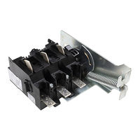
Allen-Bradley A Series Installation Instructions Manual (12 pages)
Universal Disconnect Switch
Brand:
Allen-Bradley
| Category:
Switch
| Size: 6 MB
Table of Contents
Table of Contents
1
Rod and Cable Operated Disconnect Switch Location
2
Rod Operated Switch Installation
2
Handle Installation
2
Cutting Connecting Rod
3
Connecting Rod Installation
3
Cable Operated Switch Installation
4
Handle and Cable Mechanism Installation
4
Cable to Switch Mechanism Installation
4
Rod Operated Adjustment Procedure
5
Cable Operated Adjustment Procedure
5
Enclosure Without Handle Cutout
6
Door Catch Bracket Installation
6
Trailer Fuse Block Installation
7
Fuse Clip and Fuse Installation
8
Auxiliary Contact Installation
9
Auxiliary Contact Wire Routing
9
Line Terminal Adapter Installation
9
Electrical Interlock Installation
9
Protective Cover Installation
10
Bulletin 1494U Disconnect Switch Component Accessory List
11
Advertisement
Allen-Bradley A Series Installation Instructions Manual (16 pages)
DeviceNet Network Powered 16-input Module
Brand:
Allen-Bradley
| Category:
Control Unit
| Size: 0 MB
Table of Contents
Table of Contents
1
Important User Information
2
Environment and Enclosure
3
Preventing Electrostatic Discharge
3
About the Module
4
Catalog Number Explanation
5
Install the Module
5
Set the Node Address
5
Mount the Module
6
Connect the Cordsets
8
Communicate with the Module
9
Interpret Status Indicators
10
Specifications
12
Advertisement
Related Products
Allen-Bradley ArmorPOINT I/O
Allen-Bradley AADvance
Allen-Bradley ArmorBlock MaXum B Series
Allen-Bradley A020
Allen-Bradley A025
Allen-Bradley ArmorPoint DeviceNet A Series
Allen-Bradley ArmorPOINT Series
Allen-Bradley ArmorBlock Series
Allen-Bradley ArmorBlock A Series
Allen-Bradley AT16
Allen-Bradley Categories
Control Unit
Controller
I/O Systems
Power Supply
Switch
More Allen-Bradley Manuals
Login
Sign In
OR
Sign in with Facebook
Sign in with Google
Upload manual
Upload from disk
Upload from URL