Table of Contents
Advertisement
Installation Instructions
Original Instructions
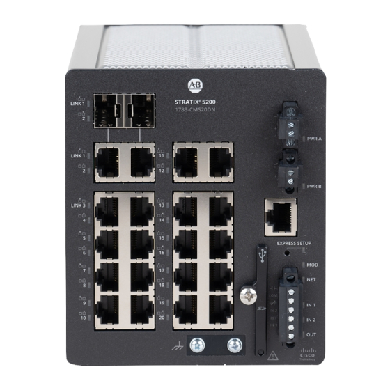
Stratix 5200 Ethernet Managed Switches
Catalog Numbers 1783-CMS6B, 1783-CMS6P, 1783-CMS10B, 1783-CMS10P, 1783-CMS10DP, 1783-CMS10DN, 1783-CMS20DB, 1783-CMS20DP, 1783-CMS20DN
Topic
Install or Remove the SD Card
Page
5
5
5
6
7
7
8
9
11
12
12
12
13
14
13
13
14
14
15
15
Advertisement
Table of Contents

Related Manuals for Allen-Bradley Stratix 5200 1783-CMS6B


Summary of Contents for Allen-Bradley Stratix 5200 1783-CMS6B
-
Page 1: Table Of Contents
Installation Instructions Original Instructions Stratix 5200 Ethernet Managed Switches Catalog Numbers 1783-CMS6B, 1783-CMS6P, 1783-CMS10B, 1783-CMS10P, 1783-CMS10DP, 1783-CMS10DN, 1783-CMS20DB, 1783-CMS20DP, 1783-CMS20DN Topic Page Parts List Required Tools Site Requirements Mount the Switch Ground the Switch Wire the DC Power Source Install the Power Connectors on the Switch Wire External Alarms Connect to Console Ports Install or Remove the SD Card... - Page 2 Stratix 5200 Ethernet Managed Switches Installation Instructions ATTENTION: Read this document and the documents listed in the Additional Resources section about installation, configuration and operation of this equipment before you install, configure, operate or maintain this product. Users are required to familiarize themselves with installation and wiring instructions in addition to requirements of all applicable codes, laws, and standards. Activities including installation, adjustments, putting into service, use, assembly, disassembly, and maintenance are required to be carried out by suitably trained personnel in accordance with applicable code of practice.
- Page 3 Stratix 5200 Ethernet Managed Switches Installation Instructions North American Hazardous Location Approval The following information applies when operating this equipment in hazardous Informations sur l’utilisation de cet équipement en environnements dangereux. locations. Products marked "CL I, DIV 2, GP A, B, C, D" are suitable for use in Class I Division 2 Les produits marqués "CL I, DIV 2, GP A, B, C, D"...
- Page 4 Stratix 5200 Ethernet Managed Switches Installation Instructions ATTENTION: This equipment is certified for use only within the surrounding air temperature range of -40…+60 °C (-40…+140 °F). The equipment must not be used outside of this range. ATTENTION: Power to this equipment and all connected I/O must be supplied from a source compliant with the following: •...
-
Page 5: Parts List
Stratix 5200 Ethernet Managed Switches Installation Instructions WARNING: The console port is intended for temporary local programming purposes only and not intended for permanent connection. If you connect or disconnect the console cable with power that is applied to this module or any device on the network, an electric arc can occur. This could cause an explosion in hazardous location installations. -
Page 6: Mount The Switch
Stratix 5200 Ethernet Managed Switches Installation Instructions • Temperature surrounding the unit does not exceed 60 °C (140 °F). IMPORTANT When the switch is installed in an industrial enclosure, the temperature within the enclosure is greater than normal room temperature outside the enclosure. -
Page 7: Ground The Switch
Stratix 5200 Ethernet Managed Switches Installation Instructions Ground the Switch For DC power connections, use UL- and CSA-rated, style 1007 or 1569 twisted-pair copper appliance wiring material (AWM) wire. Use at least 4 mm (12 AWG) wire to connect to the external grounding screw. -
Page 8: Install The Power Connectors On The Switch
Stratix 5200 Ethernet Managed Switches Installation Instructions Loosen the two captive screws that attach the power connector to the switch, and remove the power connector. Remove both connectors if you are connecting to two power sources. Insert the exposed part of the positive wire into the connection that is labeled DC+ and the exposed part of the return wire into the connection labeled DC-. Be sure that you cannot see any wire lead. -
Page 9: Wire External Alarms
Stratix 5200 Ethernet Managed Switches Installation Instructions Use a ratcheting torque flathead screwdriver to tighten the captive screws on the sides of the power connectors. When you test the switch, one power source is sufficient. If you install a second power source, repeat this procedure for the second power connector (Pwr B). When you install the switch, secure the wires from the power connectors to the rack by using tie wraps. - Page 10 Stratix 5200 Ethernet Managed Switches Installation Instructions To wire the switch to an external alarm device, follow these steps. Loosen the captive screws that hold the alarm relay connector on the switch, and remove the connector from the switch chassis. Measure two strands of twisted-pair wire (18…20 AWG) long enough to connect to the external alarm device.
-
Page 11: Connect To Console Ports
Stratix 5200 Ethernet Managed Switches Installation Instructions Connect to Console Ports The switch has both a USB micro-Type B port and an RJ-45 console port on the front panel. USB Micro-Type B Console Port Loosen the captive screw on the cover of the USB micro type B console port. The USB port shares its cover with the SD card connector. -
Page 12: Install Or Remove The Sd Card
Stratix 5200 Ethernet Managed Switches Installation Instructions Install or Remove the SD Card To install or replace the optional SD card, follow these steps. On the front of the switch, locate the door that protects the SD card slot. Loosen the captive thumbscrew at the top of the door by using a screwdriver to open the door. Be careful when pulling out the SD Card guard cover so the retainer does not pop out of place. -
Page 13: Connect To 10/100 And 10/100/1000 Ports
Stratix 5200 Ethernet Managed Switches Installation Instructions c. Remove the dust plugs from the SFP module optical ports, store them for later use. To remove an SFP module from an SFP slot, follow these steps. a. Disconnect the fiber LC connector from the SFP module. b. -
Page 14: Connect To 10Base-T, 100Base-Tx, Or 1000Base-T Ports
Stratix 5200 Ethernet Managed Switches Installation Instructions Connect to 10Base-T, 100Base-TX, or 1000Base-T Ports To connect to 10Base-T, 100Base-TX, or 1000Base-T ports, follow these steps. To connect a device, choose one of the following options: • When connecting to workstations, servers, and routers, connect a straight-through cable to an RJ45 connector on the front panel. •... -
Page 15: Specifications
Provides declarations of conformity, certificates, and other certification details. You can view or download publications at http://www.rockwellautomation.com/global/literature-library/overview.page. To order paper copies of technical documentation, contact your local Allen-Bradley distributor or Rockwell Automation sales representative. Rockwell Automation Publication 1783-IN022A-EN-P - July 2023... - Page 16 Rockwell Otomasyon Ticaret A.Ş. Kar Plaza İş Merkezi E Blok Kat:6 34752 İçerenköy, İstanbul, Tel: +90 (216) 5698400 EEE Yönetmeliğine Uygundur Allen-Bradley, expanding human possibility, Rockwell Automation, Rockwell Software, and Stratix are trademarks of Rockwell Automation, Inc Trademarks not belonging to Rockwell Automation are property of their respective companies.
Need help?
Do you have a question about the Stratix 5200 1783-CMS6B and is the answer not in the manual?
Questions and answers