Table of Contents
Advertisement
User Manual
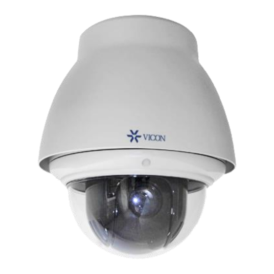
V672-PTZ Outdoor Analog PTZ Dome Camera
Vicon Industries Inc. does not warrant that the functions contained in this equipment will
meet your requirements or that the operation will be entirely error free or perform precisely
as described in the documentation. This system has not been designed to be used in life-
critical situations and must not be used for this purpose.
Document Number: 8009-8307-00-00 Product specifications subject to change without
notice. Issued: 9/18 Copyright © 2018 Vicon Industries Inc. All rights reserved.
XX307-00-00
Vicon Industries Inc.
Tel: 631-952-2288) Fax: 631-951-2288
Toll Free: 800-645-9116
24-Hour Technical Support: 800-34-VICON
(800-348-4266) UK: 44/(0) 1489-566300
www.vicon-security.com
Advertisement
Table of Contents

Related Manuals for Vicon V672-PTZ


Summary of Contents for Vicon V672-PTZ
- Page 1 V672-PTZ Outdoor Analog PTZ Dome Camera XX307-00-00 Vicon Industries Inc. Vicon Industries Inc. does not warrant that the functions contained in this equipment will Tel: 631-952-2288) Fax: 631-951-2288 meet your requirements or that the operation will be entirely error free or perform precisely Toll Free: 800-645-9116 as described in the documentation.
- Page 2 WARNING TO REDUCE THE RISK OF FIRE OR ELECTRIC SHOCK, DO NOT EXPOSE THIS PRODUCT TO RAIN OR MOISTURE. DO NOT INSERT ANY METALLIC OBJECTS THROUGH THE VENTILATION GRILLS OR OTHER OPENINGS ON THE EQUIPMENT. CAUTION CAUTION RISK OF ELECTRIC SHOCK DO NOT OPEN CAUTION: TO REDUCE THE RISK OF ELECTRIC SHOCK, DO NOT REMOVE COVER (OR BACK)
- Page 3 FCC COMPLIANCE STATEMENT This device complies with Part 15 of the FCC Rules. Operation is subject to the following two conditions: (1) this device may not cause harmful interference, and (2) this device must accept any interference received, including interference that may cause undesired operation. FCC INFORMATION: This equipment has been tested and found to comply with the limits for a Class A digital device, pursuant to Part 15 of the FCC Rules.
- Page 4 IMPORTANT SAFETY INSTRUCTIONS Read these instructions. Keep these instructions. Heed all warnings. Follow all instructions. Do not use this apparatus near water. Clean only with dry cloth. Do not block any ventilation openings. Install in accordance with the manufacturer’s instructions. Do not install near any heat sources such as radiators, heat registers, stoves, or other apparatus (including amplifiers) that produce heat.
-
Page 5: Table Of Contents
3.12 Dome Setup ........................28 Operation .......................... 34 Using a ViconNet VMS ..................... 34 Using a Valerus VMS ....................... 35 Appendix A — Specifications ..................36 Appendix B — Troubleshooting ..................38 Shipping Instructions ......................... 42 Vicon Standard Equipment Warranty ..................43... -
Page 6: Chapter 1 - Introduction
Chapter 1 — Introduction 1.1 Features Built-in optical power zoom camera with True Night Shot function 240 preset positions with the individual camera AE setup 8 tours, consisting of presets, patterns, auto scans and other tours, can be programmed with over 300 functions and preset locations. -
Page 7: Chapter 2 - Installation And Configuration
Chapter 2 — Installation and Configuration 2.1 Package Contents The package contains the following. * Dome Camera * Instruction Manual (this document) * Accessory Kit & Connectors 1) Torx wrench 2) 2-Pin Terminal Block 3) 3-Pin Terminal Block 4) 4-Pin Terminal Block 5) 5-Pin Terminal Block * Install Adaptor... -
Page 8: Mounting The Camera
2.2 Mounting the Camera An optional mount kit, either a wall mount or a ceiling mount, is required for installation. The wall or ceiling mount must be attached to a structural object such as hard wood, concrete that will support the weight of the mount and dome camera. The use of a solid backboard is recommended when attaching to gypsum walls. -
Page 9: Wall Mounting
2.2.1 Wall Mounting The wall mounting plate must be attached to a structural object such as concrete that will support the weight of the mount and dome camera. 1. Select a suitable mounting location and verify there is sufficient cable to reach the middle of the Wall Mount. -
Page 10: Ceiling Mounting
2.2.2 Ceiling Mounting The ceiling mounting plate must be attached to a structural object such as concrete that will support the weight of the mount and dome camera. 1. Select a suitable mounting location and verify there is sufficient cable to connect with cables... -
Page 11: Ptz Camera Removal For Maintenance
2.2.3 PTZ Camera Removal for Maintenance In order to perform maintenance or change hardware or DIP switch settings, remove the PTZ camera as shown below. 1. Open the cover. 2. Remove the screw. 3. To detach PTZ camera from 4. Change the DIP switch setting. external housing, turn it counterclockwise. -
Page 12: Basic Configuration Of Dome Camera System
2.3 Basic Configuration of Dome Camera System Connector Wire Color Description 24 VAC or 12 VDC+ 3-pin terminal block WHITE 24 VAC or 12 VDC- PINK HEATER & FAN 3-pin terminal block (24 VAC) BROWN GREEN TX+: RS485+ (A) 2-pin terminal block BLUE TX-: RS485- (B) GRAY... -
Page 13: Setting Dome Camera (Dip Switch)
4000 ft (1.2 km). You can set the PTZ coaxial control protocol with D1 and D2 in SW3. By default, the unit will auto- detect the system controlling the unit; the unit is set to Vicon protocol. SW3-D1... -
Page 14: Setting Dome Camera Address (Id)
2.5 Setting Dome Camera Address (ID) To prevent damage, each dome camera must have a unique address (ID). The factory default setting is 1. When using ViconNet, the dome ID is set in the VMS. Refer to section 3.10 Dome Communication for detailed information. 2.6 Connections •... -
Page 15: Getting Started
2.7 Getting Started Note: This manual pertains to working with Vicon protocol on a ViconNet/Valerus VMS or Vicon keypad. After dome camera is installed, apply power to the dome camera. The dome camera will start a configuration sequence. ViconNet screen... -
Page 16: Chapter 3 - Program And Operation
The programming instructions below are based on Vicon protocol. The dome can be controlled by a Vicon keypad or by a Vicon VMS system, ViconNet or Valerus. When using the camera with ViconNet, the camera ID is assigned within the ViconNet programming system. Only a user with administrator privileges can perform these functions. -
Page 17: Auto Scan
3.4 Auto Scan The Auto Scan supports up to 17 programmed sector angles at user-programmable speeds. Only 8 of these can be called up; the remaining can be set and used as steps in a tour if needed. Use UP/DOWN to navigate through the menu selections; use either the UP/DOWN or +/- to change the value of the selection. - Page 18 TITLE EDIT MENU (CTRL KEY) A B C D E F G H I J K L M N O P Q R S T U V W X Y Z 0 1 2 3 4 5 6 7 8 9 ( ) ALL DELETE EXIT(ESC TO EXIT) 5.
-
Page 19: Preset
3.5 Preset If you need to view specific positions routinely, you should program Presets. A Preset is a programmed video scene with automatic pan, tilt, zoom, focus, and AE settings. In addition, Presets may be assigned the “Home” position for the dome camera. Up to 59 presets (1-59), whose positions are saved in the dome camera’s firmware, may be programmed and called up. - Page 20 Select “MOTION SETUP” and use RIGHT/LEFT to display the MOTION Setup menu. MOTION SETUP SENSITIVITY : 10 POSITION : ALL DELAY : 00 SEC OUTPUT : OFF HOLD TIME : 03 SEC EXIT(ESC TO EXIT) Set SENSITIVITY 00 ~ 20 Set POSITION ALL, CENTER Set DELAY...
-
Page 21: Tour
3.6 Tour There are 8 programmable Tours. Each Tour can consists of up to 40 preset positions, patterns, auto-scans or other tours (second-level). Using second-level tours, it can be expanded to over 300 functions in a single tour. TOUR SETUP NUMBER : 01 TITLE... -
Page 22: Pattern
7. Select “DWELL” to enter the time the dome will stay in that position before moving to the next position. 8. Use the +/- to enter the preset, auto scan, pattern or tour in that position; use the RIGHT/LEFT to move to the next position. -
Page 23: Privacy Zone
3.8 Privacy Zone Use Privacy masks to hide up to 16 unwanted scenes in a camera scene. There are four pages of Privacy Zone menus. Each page has 4 Privacy Zones. PRIVACY ZONE SETUP (CTRL KEY) METHOD COLOR BLOCK BLACK BLOCK BLACK -----... -
Page 24: Camera Menu
3.9 Camera Menu Use UP/DOWN to navigate the menu and RIGHT/LEFT or +/- to change the settings in the Camera Setup menu. CAMERA SETUP FOCUS CONTROL WB CONTROL AE CONTROL CAMERA CONTROL SHARPNESS : 03 DIGITAL ZOOM : OFF IMAGE FLIP : OFF PRESET FREEZE : OFF... - Page 25 • WB (White Balance) CONTROL WB SETUP MODE : AUTO R GAIN : --- B GAIN : --- SAVE AND EXIT(ESC TO CANCEL) MODE AUTO, MANUAL, INCANDESCENT, FLUORESCENT, OUTDOOR AUTO Computes the white balance value output using color information from the entire screen automatically. INCANDESCENT Auto white balance mode that is compatible with incandescent lighting.
- Page 26 The NIGHT SHOT option removes the IR cutoff filter of the camera and makes the camera sensitive to near infrared. AUTO Camera goes into B&W mode at low light. GLOBAL Not Available. B/W mode. Color mode. NOTE: AUTO in NIGHT SHOT function is not available in “MANUAL” mode of AE Control. ADDITIONAL AE ADDITIONAL AE SETUP : OFF...
-
Page 27: Dome Communication
PARITY : NONE SAVE AND EXIT(ESC TO CANCEL) DOME ID 1 ~ 3999 available; Vicon’s limit is up to 255. PROTOCOL AUTO*, (F2/F2E, PELCO-PD are not Vicon protocol). BAUDRATE 2400, 4800, 9600, 19200, 38400 bps; all units in the system must be set to the same baud rate. -
Page 28: Dome Setup
ALARM OUT SETUP Use RIGHT/LEFT to open Alarm Out Setup menu. ALARM OUT SETUP OUT1 : ALARM OUT2 : 1 MIN EXIT(ESC TO EXIT) ALARM: Alarm output is active during an alarm operation. 1 ~ 5 MIN (minute): Alarm output is active during this set time only by the function run of the dome menu. - Page 29 Follow these steps to program the Home position: 1. Select FUNCTION and use RIGHT/LEFT or +/- to scroll through the None, Tour, Pattern, Auto Scan or Preset functions. If NONE is selected, the other settings in the menu are not available. 2.
- Page 30 • ORIGIN OFFSET Use UP/DOWN to navigate the menu and RIGHT/LEFT or +/- to change the settings in the Offset Setup menu. This menu requires using the CTRL key, preset 95. OFFSET SETUP (CTRL KEY) PAN OFFSET : 000.0 TILT OFFSET : 000.0 ENABLE : OFF...
- Page 31 ON (5 minutes), OFF (menu always display) DOME ANSWER ON, OFF (no acknowledge command from the dome). This setting is not applicable for Vicon protocol, which is simplex. This option is helpful to avoid a collision of the commands in some systems. PRESET FOCUS AUTO, MANUAL, ONE PUSH.
- Page 32 NORMAL TILT maximum speed 40 ~ 200/second TURBO PAN maximum speed 200 ~ 380/second TURBO TILT maximum speed 90 ~ 300/second Note: The SLOW and TURBO setting do not work with Vicon protocol. PASSWORD EDIT PASSWORD EDIT SETUP (CTRL KEY) INPUT PASSWORD PASSWORD:...
- Page 33 HOME position after the origin check operation. ORIGIN CHECK ARE YOU SURE ? CANCEL • FUNCTION RUN The Function Run menu is not applicable in a Vicon system. • SYSTEM INFORMATION SYSTEM INFORMATION CAMERA TYPE : xxxx-Vx.xx H/W VERSION : Vx.xx-xxxx...
-
Page 34: Operation
Operation The V672-PTZ can be operated from the ViconNet or Valerus VMS as well as from a keypad. Using a ViconNet VMS PTZ dome cameras can be easily operated and controlled from the ViconNet Main window. Note that an appropriate encoder must be used to with the camera and VMS. -
Page 35: Using A Valerus Vms
Using a Valerus VMS PTZ dome cameras can be easily operated and controlled from the Valerus Monitoring screen. Note that an appropriate encoder must be used to with the camera and VMS. 1. Select the required PTZ camera from the Resources List and drag to a tile to display. 2. -
Page 36: Appendix A - Specifications
Appendix A — Specifications Model V672-PTZ HD Analog Camera IMAGE Optical Zoom 30X Lens 4.3mm ~ 129.0mm Angle of View 61.8° (H) ~ 2.9° (H) Type 1/2.8" SONY STARVIS CMOS sensor Image Sensor Pixels 1945 (H) x 1097 (V) Color : 0.35 Lux @ 50IRE Min. - Page 37 Operating Humidity 0 ~ 90%RH (Non-condensing) Operating Temperature -58F ~ 149F (-50C ~ 65C) Camera 12 VDC, 24 VAC Power Supply Heater & Fan 24 VAC Camera 1.0A (12.0W) @ 12VDC, 24VAC Power Consumption Heater & Fan 2.2A (50.0W) @ 24VAC Dimensions See dimension drawing Net Weight...
-
Page 38: Appendix B - Troubleshooting
Appendix B — Troubleshooting If problems occur, verify the installation of the camera with the instructions in this manual and with other operating equipment. Isolate the problem to the specific piece of equipment in the system and refer to the equipment manual for further information. Problem Possible Solution Verify that power is connected to all pieces of equipment... -
Page 39: Shipping Instructions
Shipping Instructions Use the following procedure when returning a unit to the factory: 1. Call or write Vicon for a Return Authorization (R.A.) at one of the locations listed below. Record the name of the Vicon employee who issued the R.A. -
Page 40: Vicon Standard Equipment Warranty
“autopan” or “tour” modes of operation. Such continuous operation is outside the scope of this warranty. 11. Any product sold as “special” or not listed in Vicon’s commercial price list: One year from date of original retail purchase. - Page 41 THE TERMS OF THIS WARRANTY APPLY ONLY TO SALES MADE WHILE THIS WARRANTY IS IN EFFECT. THIS WARRANTY SHALL BE OF NO EFFECT IF AT THE TIME OF SALE A DIFFERENT WARRANTY IS POSTED ON THE COMPANY’S WEBSITE, WWW.VICON-SECURITY.COM. IN THAT EVENT, THE TERMS OF THE POSTED WARRANTY SHALL APPLY EXCLUSIVELY.
Need help?
Do you have a question about the V672-PTZ and is the answer not in the manual?
Questions and answers