Table of Contents
Advertisement
Quick Links
Installation and Operation Guide
XX229-11-00
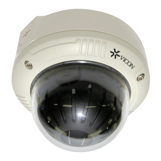
V661D-312N-1 Indoor/Outdoor
Analog Camera Dome
Vicon Industries Inc.
Tel: 631-952-2288
Fax: 631-951-2288 Toll Free: 800-645-9116
24-Hour Technical Support: 800-34-VICON (800-348-4266) UK: 44/(0) 1489-566300
Vicon Industries Inc. does not warrant that the functions contained in this equipment will meet your requirements or that the
operation will be entirely error free or perform precisely as described in the documentation. This system has not been designed
to be used in life-critical situations and must not be used for this purpose.
www.vicon-security.com
Document Number: 8009-8229-01-00
Issued: 0615
Advertisement
Table of Contents

Related Manuals for Vicon V661D-312N-1


Summary of Contents for Vicon V661D-312N-1
- Page 1 24-Hour Technical Support: 800-34-VICON (800-348-4266) UK: 44/(0) 1489-566300 Vicon Industries Inc. does not warrant that the functions contained in this equipment will meet your requirements or that the operation will be entirely error free or perform precisely as described in the documentation. This system has not been designed to be used in life-critical situations and must not be used for this purpose.
-
Page 2: Fcc Compliance Statement
FCC COMPLIANCE STATEMENT This device complies with Part 15 of the FCC Rules. Operation is subject to the following two conditions: (1) this device may not cause harmful interference, and (2) this device must accept any interference received, including interference that may cause undesired operation. FCC INFORMATION: This equipment has been tested and found to comply with the limits for a Class A digital device, pursuant to Part 15 of the FCC Rules. -
Page 3: Important Safety Instructions
IMPORTANT SAFETY INSTRUCTIONS EXPLANATION OF GRAPHICAL SYMBOLS... -
Page 4: Camera Connections
INTRODUCTION The V661D-1 series of cameras provides high-quality images using CCD technology especially designed for closed-circuit television (CCTV) and security surveillance applications. Features: High resolution and high performance Privacy Mask (8 positions, 16 colors) 1/3” CCD Technology AGC (Auto Gain Control) Excellent picture quality Mirror (ON / OFF) 700 lines (color) of resolution... -
Page 5: Surface Mount
- Surface Mount 1. Loosen the three Torx screws as shown in Figure 1. Do not remove the screws. Lift the trim ring off the mount and set aside. 2. Drill the mounting location using the supplied drilling guide. 3. Attach the surface mount to the ceiling as shown in Figure 2. M5x30 fasteners are supplied;... - Page 6 - Surface Mount Locking flap's Screws(x3) Locking flap(x3)
- Page 7 - In Ceiling Note: The ceiling tile cannot be thinner than 0.15 Inch (3.7mm) 1. Loosen the three Torx screws as shown in Figure 1. Do not remove the screws. Lift the trim ring off the mount and set aside. Note: Set the surface mount aside.
- Page 8 - In Ceiling Locking flap's Screws(x3) Locking flap(x3)
-
Page 9: Lens Adjustment
Lens Adjustment Field of View: Adjust setting from Telephoto (T) to wide (W) for Field of View. ∞ Focus: Adjust lens focus from near (N) to infinity ( Note: To access the lens, press the two finger tabs on the shroud to remove the shroud. Refer to Figure 2- Adjust Focus Adjust Anguler Feild View DC Auto iris Lens... -
Page 10: The Definition Of Terms
THE DEFINITION OF TERMS White Balance Compensates for deviations in the white color caused by changes in the color temperature of the light source so that the colors are reproduced correctly. Auto Exposure Automatically adjusts the images to the optimum brightness. SHT(Electronic Shutter) Controls the integration time (exposure) of the photodiode array and reduces, blooming overexposure, and smear when capturing moving objects. - Page 11 Frame Control Specifies how many frames are generated/transmitted in a unit of time. The more frames there are, the smoother the image will be, The television system(NTSC/PAL) has adopted 30/25 frames per second(fps) to be regarded as completely smooth image. However, when recording video data, video surveillance systems often use lower fram rates to reduce the size of the recording data.
-
Page 12: Structure Of The Setup Menu
STRUCTURE OF THE SETUP MENU... -
Page 13: Lens Selection
Use the joystick to navigate the setup menus. Move it up or down to move the cursor to select the menu option, left or right to view setting options and press to select. LENS (Selection) This function is used to adjust the brightness of the screen. 1. - Page 14 Use the WHITE BALANCE function to adjust the color according to the lighting conditions of the scene. 1) ATW1 Set the color temperature 2500˚K - 10000˚K Set the color temperature 2000˚K -13000˚K 2) ATW2 3) AUTO -> SET Press the joystick button while the camera is directed at a piece of white paper to obtain the optimum state under current illumination.
- Page 15 The DAY / NIGHT menu is used to configure how the camera handles color and changes between day and night mode. This camera can turn the IR (infrared) filter on or off by selecting B/W mode. Modes: AUTO / COLOR / B/W. From AUTO, adjust the day and night transition settings. Dead Pixel Compensation (DPC) finds dead pixels in the image, marks them digitally and compensates for them to get a complete image.
- Page 16 The motion menu allows the camera to be configured for detecting motion (MD) in the scene. Up to 4 detection areas can be configured. This can be turned ON or OFF. When motion is detected in the selected area, the detection areas are displayed on the screen when turned ON.
- Page 17 3) PRIVACY The privacy mask function hides areas of a scene that the user does not want to display. Up to 8 masks can be configured. AREA SELECT Select MASK area number (AREA1 ~ AREA8) AREA STATE Select MASK ON / OFF Adjust height of MASK area HEIGHT WIDTH...
-
Page 18: Image Adjust
IMAGE ADJUST provides image adjustment features for the camera. Adjust lens shading level (0~255) to adjust image brightness in the corners 1) LENS SHAD Select 2DNR ON / OFF to adjust the luminance noise level in low light situations 2) 2DNR Select MIRROR ON / OFF to reverse the image on the horizontal frame (left-right) as seen in a mirror 3) MIRROR... -
Page 19: Specifications
SPECIFICATIONS V661D-312N-1 V661N-312-1-P AC 24V / DC 12V - 200mA (2.5 Watts) DC Jack / 2Pin Wire ˚ ˚ ˚ ˚ Φ143x4.48In(H) / Φ143x114mm(H) - Page 20 (3.8) 143.4(5.6) 0.1 in. (3.0mm thick), impact-resistant P.C(LEXAN) 3.9in (9.9cm)diameter 1.16 lb. (0.53kg) 1.49 lb. (0.68kg) Unit : mm(inch)
-
Page 21: Shipping Instructions
Shipping Instructions Use the following procedure when returning a unit to the factory: 1. Call or write Vicon for a Return Authorization (R.A.) at one of the locations listed below. Record the name of the Vicon employee who issued the R.A. -
Page 22: Coaxial Cable Recommendations
Coaxial Cable Recommendations Caution: Careful selection of proper cable is essential to obtain the best performance from this equipment. Vicon assumes no responsibility for poor performance when cables other than those recommended, or equivalent, are installed. In all cases, coaxial cable impedance should be 75 ohms. -
Page 23: Vicon Standard Equipment Warranty
“autopan” or “tour” modes of operation. Such continuous operation is outside the scope of this warranty. 10. Any product sold as “special” or not listed in Vicon’s commercial price list: One year from date of original retail purchase. - Page 24 Except as provided in this written warranty and to the extent permitted by law, neither VIcon nor any affiliated shall be liable for any loss, (including loss of data and information), inconvenience, or damage, including, but not limited to, direct, special, incidental or consequential damages, resulting from the use or inability to use the Vicon product, whether resulting from breach of warranty or any other legal theory.
- Page 25 PRECAUTIONS Before installation, carefully read the manual to ensure correct operation and setup, heeding all warnings and instructions. Do not block any ventilation openings. Install in accordance with the manufacturer's instructions. Ensure manual is kept in good condition for future use. Do not install the device near any heat sources such as radiators, heat registers, stoves, or other equipment (including amplifiers) that produce heat.
- Page 28 Vicon Industries Inc. Internet Address: www.vicon-security.com Rev.A 50303785A...
Need help?
Do you have a question about the V661D-312N-1 and is the answer not in the manual?
Questions and answers