Lincoln Electric V160-S Service Manual
Hide thumbs
Also See for V160-S:
- Service manual (107 pages) ,
- Operator's manual (29 pages) ,
- Operator's manual (12 pages)
Table of Contents
Advertisement
For use with machines having Code Numbers: 10877, 10878
Safety Depends on You
Lincoln arc welding and cutting
equipment is designed and built
with safety in mind. However, your
overall safety can be increased by
proper installation ... and thought-
ful operation on your part. DO
NOT INSTALL, OPERATE OR
REPAIR THIS EQUIPMENT
WITHOUT
READING
THIS
MANUAL AND THE SAFETY
PRECAUTIONS CONTAINED
THROUGHOUT.
And,
most
importantly, think before you act
and be careful.
• Sales and Service through Subsidiaries and Distributors Worldwide •
Cleveland, Ohio 44117-1199 U.S.A. TEL: 216.481.8100 FAX: 216.486.1751 WEB SITE: www.lincolnelectric.com
RETURN TO MAIN MENU
V160-S & -T
SERVICE MANUAL
• World's Leader in Welding and Cutting Products •
11031, 11032
Copyright © Lincoln Global Inc.
SVM177-A
October, 2007
Advertisement
Chapters
Table of Contents

Related Manuals for Lincoln Electric V160-S


Summary of Contents for Lincoln Electric V160-S
- Page 1 RETURN TO MAIN MENU SVM177-A October, 2007 V160-S & -T For use with machines having Code Numbers: 10877, 10878 11031, 11032 Safety Depends on You Lincoln arc welding and cutting equipment is designed and built with safety in mind. However, your overall safety can be increased by proper installation ...
- Page 2 Miami, Florida 33135 or CSA Standard W117.2-1974. A Free copy of “Arc Welding Safety” booklet E205 is available from the Lincoln Electric Company, 22801 St. Clair Avenue, Cleveland, Ohio 44117-1199. BE SURE THAT ALL INSTALLATION, OPERATION, MAINTENANCE AND REPAIR PROCEDURES ARE PERFORMED ONLY BY QUALIFIED INDIVIDUALS.
- Page 3 SAFETY ELECTRIC SHOCK can kill. ARC RAYS can burn. 3.a. The electrode and work (or ground) circuits 4.a. Use a shield with the proper filter and cover are electrically “hot” when the welder is on. plates to protect your eyes from sparks and Do not touch these “hot”...
- Page 4 SAFETY WELDING SPARKS can CYLINDER may explode cause fire or explosion. if damaged. 6.a. Remove fire hazards from the welding area. 7.a. Use only compressed cylinders If this is not possible, cover them to prevent containing the correct shielding gas for the the welding sparks from starting a fire.
- Page 5 SAFETY PRÉCAUTIONS DE SÛRETÉ 6. Eloigner les matériaux inflammables ou les recouvrir afin de prévenir tout risque dʼincendie dû aux étincelles. Pour votre propre protection lire et observer toutes les instructions 7. Quand on ne soude pas, poser la pince à une endroit isolé de et les précautions de sûreté...
- Page 6 Troubleshooting and Repair (V160-S / T) ........
-
Page 7: Table Of Contents
TABLE OF CONTENTS - INSTALLATION SECTION V160-S Installation ................A-1 Technical Specifications . - Page 8 INSTALLATION TECHNICAL SPECIFICATION V160-S INPUT - SINGLE PHASE ONLY Input Voltages / 50 /60 Hz. Max. Input Current at rated Output 115 V (20 A branch) 20 A 115 V (30 A branch) 25 A 230 V 34 A RATED OUTPUT...
-
Page 9: Installation
5 minutes minimum to allow the power capacitors • Always wear dry insulating gloves. to discharge before working inside this equipment. • Do not touch electrically live parts. • Always connect the V160-S to a power supply ----------------------------------------------------------------------- grounded according to the National Electrical Code GROUND CONNECTION and local codes. - Page 10 115V INPUT • Failure to wire as instructed may cause personal The rated output of the V160-S is available when con- injury or damage to equipment. To be installed or nected to a 30A branch circuit. When connected to a...
-
Page 11: Output Connections
Many engine drives do not meet these conditions (eg this purpose; however, any similar TIG torch can be Miller Bobcats, etc). Operation of the Invertec V160-S used. To attach the Twist-Mate Plug to a Lincoln Torch, is not recommended on engine drives not conforming slide the rubber boot onto the torch cable (enlarge the to these conditions. -
Page 12: Quick Disconnect Plug
TIG mode (GTAW), WITHOUT a remote control device 1. Cut off welding cable lug, if present. connected to the V160-S, the output will come on auto- 2. Remove .75 in. (19mm) of welding cable insulation. matically. WITH a remote control device connected to 3. - Page 13 DIP Switch 6: European/USA Machine Configuration ........B-6 V160-S & -T...
-
Page 14: Operation
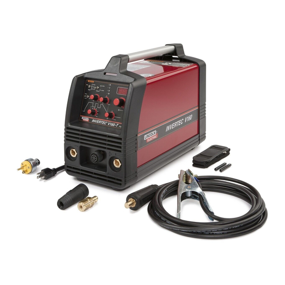
GENERAL DESCRIPTION Read and understand this entire section before operating your machine. SAFETY INSTRUCTIONS The Invertec V160-S is an industrial 160 amp arc weld- ing power source which utilizes single phase input WARNING power, to produce constant current output. The weld- ing response of this Invertec has been optimized for stick (SMAW) and Touch Start TIG (GTAW). -
Page 15: Rear Control Panel
115V input. 3. Mode Switch: This switch changes the welding modes of the machine. The V160-S has two welding 6. Thermal LED: This indicator will turn on when the modes: Stick (SMAW) and Lift TIG (GTAW). - Page 16 (Note: Any remote control device with trigger-only circuit, such as the K814 Arc Start 12. “Twist-Mate” Connection (Positive): Switch, will not be sensed by the V160-S remote control connection, and therefore will not allow con- trol of the output).
-
Page 17: Dip Switch Functions (Service Information
OPERATION DIP SWITCH FUNCTIONS DIP Switch 1: Machine Type This controls the output of the V160-S and some weld- ing waveform functions. It configures the V160-S to his section has 8 DIP switch functions of the V160-S. automatically turn ON depending on the position of the Read and understand the functions before making any Welding Mode switch. -
Page 18: Dip Switch 6: European/Usa Machine Configuration
OFF and a trigger is need- ed. Simple Lift-TIG welding is possible using a 2- step trigger sequence. DIP Switch 7 thru 8 non-functional for the V160-S. START/CRATER CURRENT ADJUSTMENT It is not possible to change the start/crater current of a "S"... - Page 19 Factory, Field Installed ..............C-2 V160-S & -T...
- Page 20 K870 - Foot Amptrol for TIG welding. When the are available for welding stainless steel, mild steel, alu- V160-Sʼs Output Control is in the “REMOTE” position, minum and copper alloys. See publication C9.10. the foot Amptrol energizes the output and controls the output remotely.
- Page 21 Routine Maintenance ..............D-2 V160-S & -T...
- Page 22 •Disconnect the power supply before every opera- tion. ------------------------------------------------------------------------ Carry out the following periodic controls on the power source: • Clean the power source inside by means of low- pressure compressed air. • Check the electric connections and all the connec- tion cables. V160-S & -T...
- Page 23 Insulated Gate Bipolar Transistor (IGBT) Operation ......... .E-6 FIGURE E.1 – V160-S BLOCK LOGIC DIAGRAM...
- Page 24 GENERAL DESCRIPTION WELDING CAPABILITY The V160-S is an industrial 160 amp arc welding The Invertec V-160-S is rated at 160 amps, 26.4 volts, power source which utilizes single phase input power, at 35% duty cycle on a ten minute basis. It is capable to produce constant current output.
- Page 25 PRECHARGE input board) that limit the charge current. During precharge time, an automatic system (manages by The Invertec V160-S can be connected to a 115V or reconnect board mounted on the input board) sets 230V single phase input voltage. the input board for 115V or 230V working mode (volt- This unit can also connect to engine driven genera- age duplicator when 115Vac is applied).
- Page 26 - Output circuit: The output diodes rectify the output the current from the main transformer. The choke fil- ters the output current.The shunt provides output feedback information to the control board. NOTE: Unshaded areas of Block Logic Diagram are the subject of discussion V160-S & -T...
- Page 27 - Display board: Supports all the potentiometer, switches and LED NOTE: Unshaded areas of Block Logic Diagram are the subject of discussion V160-S & -T...
- Page 28 F F I I G G U U R R E E E E . . 6 6 - - I I G G B B T T POSITIVE VOLTAGE APPLIED GATE GATE SOURCE SOURCE BODY REGION BODY REGION DRAIN DRIFT REGION DRAIN DRIFT REGION BUFFER LAYER BUFFER LAYER INJECTING LAYER INJECTING LAYER DRAIN DRAIN A. PASSIVE B. ACTIVE V160-S & -T...
- Page 29 Remote Control Connection ............AA-7 V160-S & -T...
-
Page 30: Installation
230/50/60 PHYSICAL DIMENSIONS Height Width Depth Weight 12.6 in. 7.9 in. 16.9 in. Approx. 24.2lbs. 320 mm 200 mm 430 mm 11 kgs. TEMPERATURE RANGES OPERATING TEMPERATURE RANGE STORAGE TEMPERATURE RANGE -20°C to +40°C -50°C to +85°C V160-S & -T... -
Page 31: Select Suitable Location
Read the section on “Machine Grounding and High Frequency Interference Protection” in this manual. • When operated in ambient temperatures greater than 40°C, the output duty cycle may be reduced. V160-S & -T... -
Page 32: Input Connections
(as in 5 (b) above) around the periphery of the build- ing are recommended. • lnstall only plugs that are corresponding to safe- ty regulations. Failure to observe these recommended installation ------------------------------------------------------------------------ procedures can cause radio or TV interference prob- lems. V160-S & -T... - Page 33 ARFU device. It only operates when the input is con- The following Lincoln engine drives meet these condi- nected to an 115V supply and protects from input over tions when run in the high idle mode: current conditions. V160-S & -T...
-
Page 34: Output And Gas Connection For Tig Welding
Insert the connector with the key lining up with the key- way, and rotate approximately 1/4 turn clockwise; until COMPOSÉ DE RETENUE LE TIG INCENDIENT LE CABLE ÉLECTRIQUE AVEC LE GAZ FITING the connection is snug. Do not over tighten. V160-S & -T... -
Page 35: Quick Disconnect Plug
• Arc Start Switch (K814). SET SCREW BRASS PLUG COPPER TUBE 8. Slide rubber boot over brass plug. The rubber boot must be positioned to completely cover all electrical surfaces after the plug is locked into the receptacle. V160-S & -T... - Page 36 NOTES AA-8 AA-8 V160-S & -T...
- Page 37 Start/Crater Current Adjustment ........... . .BB-12 V160-S & -T...
-
Page 38: Operation
• Do not weld, cut or gouge on containers that have held com- bustibles. ____________________________________ ARC RAYS can burn. • Wear eye, ear and body protection. ____________________________________ Only qualified personnel should operate this equip- ment. Observe all safety information throughout this manual. V160-S & -T... -
Page 39: Rear Control Panel
Stick (SMAW), Lift TIG (GTAW) and HF TIG (GTAW). When the mode switch is in the Stick position, the fol- lowing welding features are enabled: FIGURE BB.1 1. Power Switch 2. Fan 3. Gas Inlet V160-S & -T... - Page 40 7. Thermal LED 17. Background Current Control 8. Remote LED 18. Electrode Connection (Negative) 9. Output LED 19. Remote Control Connector 10. Output Current Control 20. Electrode Connection (Positive) 11. Downslope Control 12. Postflow Control 13. Digital Display V160-S & -T...
- Page 41 The machine will open the gas valve to start the flow of the shielding gas. After a 0.5 second preflow time to purge air from the torch hose, the output of the machine is turned ON. At this time the arc can be started. V160-S & -T...
- Page 42 The duration of this postflow time is adjusted by the Postflow control knob. This operation is shown in (4 step diagram 1). 4 Step Diagram 1 V160-S & -T...
-
Page 43: Dip Switch Functions (Service Information
FIGURE BB.3 are performed only by qualified indi- viduals. Lincoln Electric is not responsible for damages caused by improper Front of machine installation, improper care or abnormal operation. Before opening the machine to make changes to the DIP Switches it must first be turned OFF and disconnected from the input source. -
Page 44: Dip Switch 3: 2 Step Restart Enable
TIG torch trigger a second time during downs- lope to end the downslope time and maintain the out- put current at the Start/Crater current. When the TIG torch trigger is released the output will turn OFF and the postflow time will start. FIGURE BB.5 V160-S & -T... -
Page 45: Dip Switch 4: 4 Step Restart Enable
3A. If it is not necessary to maintain the Start/Crater current, the TIG torch trigger can be pressed and released instead of holding it. In this case, step 4 will automatically follow. V160-S & -T... - Page 46 When the TIG torch trigger is released the output will again increase (upslope) to the welding current, like in step 4, to continue welding. When the main part of the weld is complete go to step 3. V160-S & -T...
-
Page 47: Dip Switch 5: Low Ocv Enable
• No remote control connected. The TIG slope func- tions are enabled. After the arc is started the output current will be increased (upslope) to the welding current. At the end of the weld the current will be decreased with the downslope function. V160-S & -T... -
Page 48: Dip Switch 7 & 8: Upslope Timer
The by qualified individuals. Lincoln Electric is not access hole for this trimmer is the higher one on the responsible for damages caused by improper display board. - Page 49 Factory, Field Installed ..............CC-2 V160-S & -T...
- Page 50 PTA-17 12.5 ft long back cap • K1782-3 PTA-17 25 ft long back cap NOTE: Each torch requires a Twist-Mate adapter,(one is included with the machine). Collects, collect bodies, and nozzles are not included and must be ordered separately. V160-S & -T...
- Page 51 Major Component Location for V160S/T ..........DD-3 V160-S & -T...
- Page 52 •Disconnect the power supply before every opera- tion. ------------------------------------------------------------------------ Carry out the following periodic controls on the power source: • Clean the power source inside by means of low- pressure compressed air. • Check the electric connections and all the connec- tion cables. V160-S & -T...
- Page 53 MAINTENANCE DD-3 DD-3 1) Front Assembly 2) Rear Assembly 3) Base/Main Assembly Figure DD.1 - Major Component Locations V160-S & -T...
- Page 54 NOTES DD-4 DD-4 V160-S & -T...
- Page 55 • Do not operate with coers removed. • Disconnect input power by unplugging power cord before servicing. REMOTE • Do not touch electrically live parts. CONNECTOR • Only qualified persons should install, use or service this machine V160-S & -T...
- Page 56 Fleetweld 37, Fleetweld 180 and Jet-LH 78 MR. It fea- tures adjustable arc control to adjust the arc force and start. LIMITATIONS The V160-S is not recommended for pipe thawing. NOTE: Unshaded areas of Block Logic Diagram are the subject of discussion V160-S & -T...
- Page 57 The initial power is applied to the Invertec V160-T present. The fan shuts down after 5 minutes when directly on the input board. A line switch located on the output is shut off. NOTE: Unshaded areas of Block Logic Diagram are the subject of discussion V160-S & -T...
- Page 58 - Output circuit: The output diodes rectify the output the current from the main transformer. The choke fil- ters the output current.The shunt provides output feedback information to the control board. NOTE: Unshaded areas of Block Logic Diagram are the subject of discussion V160-S & -T...
- Page 59 - Display board: Supports all the potentiometer, switches and LED - Meter board: Displays the pre-set and actual output current NOTE: Unshaded areas of Block Logic Diagram are the subject of discussion V160-S & -T...
- Page 60 F F I I G G U U R R E E E E E E . . 6 6 - - I I G G B B T T POSITIVE VOLTAGE APPLIED GATE GATE SOURCE SOURCE BODY REGION BODY REGION DRAIN DRIFT REGION DRAIN DRIFT REGION BUFFER LAYER BUFFER LAYER INJECTING LAYER INJECTING LAYER DRAIN DRAIN B. ACTIVE A. PASSIVE V160-S & -T...
- Page 61 Retest After Repair ..............F-38 V160-S & -T...
-
Page 62: Troubleshooting And Repair
HOW TO USE TROUBLESHOOTING GUIDE WARNING Service and Repair should only be performed by Lincoln Electric Factory Trained Personnel. Unauthorized repairs performed on this equipment may result in danger to the technician and machine operator and will invalidate your factory warranty. For your safety and to avoid Electrical Shock, please observe all safety notes and precautions detailed throughout this manual. - Page 63 Do not touch electrically hot parts. - If you return a PC board to The Lincoln Electric Company for credit, it must be in the static-shielding CAUTION bag. This will prevent further damage and allow prop- er failure analysis.
- Page 64 3. Check the welding cable CAUTION If for any reason you do not understand the test procedures or are unable to perform the tests/repairs safely, contact the Lincoln Electric Service Department for technical troubleshooting assistance before you proceed. Call 1-888-935-3877. V160-S & -T...
- Page 65 2. Perform the Inverter oard Test CAUTION If for any reason you do not understand the test procedures or are unable to perform the tests/repairs safely, contact the Lincoln Electric Service Department for technical troubleshooting assistance before you proceed. Call 1-888-935-3877. V160-S & -T...
- Page 66 NOTES V160-S & -T...
- Page 67 CASE COVER REMOVAL AND REPLACEMENT PROCEDURE WARNING Service and repair should be performed by only Lincoln Electric factory trained personnel. Unauthorized repairs performed on this equipment may result in danger to the technician or machine operator and will invalidate your factory warranty. For your safety and to avoid electrical shock, please observe all safety notes and precautions detailed throughout this manual.
- Page 68 2. Using a phillips head screwdriver, remove the four screws on the back. See Figure F.1 3. Pull out the rear panel, take off the handle, then remove the cover. 4. Perform Discharge Procedure detailed in this Input Filter Capacitor section. V160-S & -T...
- Page 69 If for any reason you do not understand the test procedures or are unable to per- form the test / repairs safely, contact the Lincoln Electric Service Department for electrical troubleshooting assistance before you proceed. Call 1-888-935-3877.
- Page 70 3. Be careful not to make contact with the capacitor solder pads located on the input board. See Figure F.2. FIGURE F.2 – LOCATION OF INPUT FILTER CAPACITOR TERMINALS ON THE INPUT BOARD INSULATED PLIERS INSULATED GLOVES V160-S & -T...
-
Page 71: Input Board Test
If for any reason you do not understand the test procedures or are unable to per- form the test / repairs safely, contact the Lincoln Electric Service Department for electrical troubleshooting assistance before you proceed. Call 1-888-935-3877. - Page 72 FIGURE F.3 – INPUT BOARD Input Board TEST PROCEDURE 1. Remove input power to the V160S/T 2. Perform Case Removal Procedure. 3. Perform the Input Filter Capacitor Discharge Procedure detailed earlier in this section. 4. Locate the Input board. Figure F.3. V160-S & -T...
- Page 73 TEST PROCEDURE 1. Locate test points. See figure F.4. 2. Check capacitors + input bridge for open or shorts. See input board schematic. 3. Check Fuse F1. 4. Check start resistor for 20 ohms. V160-S & -T...
- Page 74 Pin 9 = +5Vdc TEST PROCEDURE 1. Locate connector JP1. See figure F.5. 2. Check pin 5 to pin 11 for -5vdc. 3. Check pin 7 to pin 11 for +15vdc. 4. Check pin 9 to pin 11 for +5vdc. V160-S & -T...
- Page 75 320 Vdc AC1 AC2 DC- DC+ TEST PROCEDURE 1. Locate test points. See Figure F.6. 2. Check AC1 + AC2 for 115 VAC or 230 VAC depending on input voltage. 3. Check DC+ to DC- for 320Vdc. V160-S & -T...
- Page 76 TROUBLESHOOTING & REPAIR F-16 F-16 INPUT BOARD TEST V160-S/T (continued) FIGURE F.6A – INPUT BOARD CONNECTOR JP1 Check Capacitors F2 0 Ohms F1 Fuse For Shorts PIN 15 PIN 1 PIN 16 PIN 2 Start Resistor 20 Ohms TEST PROCEDURE: 1.
- Page 77 TROUBLESHOOTING & REPAIR F-17 F-17 INPUT BOARD TEST V160-S/T (continued) FIGURE F.7 – INPUT BOARD V160 INPUT PCB INSIDE F1 Fuse Protects Revision Number Reconnect Transformer F2 Thermostat -5 VDC Supply +5 VDC Supply +15 VDC Supply Start Resistor Reconnect Relay...
- Page 78 TROUBLESHOOTING & REPAIR F-18 F-18 INPUT BOARD TEST V160-S/T (continued) FIGURE F.8 – INPUT BOARD V160 TOP VIEW V160 TOP VIEW 115AC or 230AC Input Input PCB F2 Thermostat 320 VDC Input DC- 320 VDC Input DC+ Output Same As...
-
Page 79: Main Igbt Inverter Board V160-T "Welding Logic And Inverter" Section Test
If for any reason you do not understand the test procedures or are unable to per- form the test / repairs safely, contact the Lincoln Electric Service Department for electrical troubleshooting assistance before you proceed. Call 1-888-935-3877. - Page 80 TROUBLESHOOTING & REPAIR F-20 F-20 MAIN IGBT INVERTER BOARD V160-S/T “WELDING LOGIC AND INVERTER” SECTION TEST (continued) TEST PROCEDURE 1. Remove input power to the V160S/T machine. 2. Perform Case Cover Removal Procedure. 3. Perform Procedure detailed earlier in this section.
- Page 81 TROUBLESHOOTING & REPAIR F-21 F-21 MAIN IGBT INVERTER BOARD V160-S/T “WELDING LOGIC AND INVERTER” SECTION TEST (continued) FIGURE F.10 MAIN IGBT INVERTER BOARD LOCATION VOLTAGE CHECKS ON JP1 INVERTER BOARD CHECK FOR 320 VDC REFER PIN 2 AS GROUND PIN 3 = 15 VDC...
- Page 82 TROUBLESHOOTING & REPAIR F-22 F-22 MAIN IGBT INVERTER BOARD V160-S/T “WELDING LOGIC AND INVERTER” SECTION TEST (continued) FIGURE F.11 MAIN IGBT INVERTER BOARD LOCATION WAVEFORM ON EACH GATE 5us/div 10V/div Take note that you need an oscilloscope insulated from 1 3 5 7 9...
- Page 83 TROUBLESHOOTING & REPAIR F-23 F-23 MAIN IGBT INVERTER BOARD V160-S/T “WELDING LOGIC AND INVERTER” SECTION TEST (continued) FIGURE F.12 MAIN IGBT INVERTER BOARD LOCATION CHECK THE IGBT S FOR SHORTS (AN OPEN STATUS NORMALLY IS EVIDENT) CHECK FOR THERMAL PROTECTION (~ 36 OHMS)
- Page 84 TROUBLESHOOTING & REPAIR F-24 F-24 MAIN IGBT INVERTER BOARD V160-S/T “WELDING LOGIC AND INVERTER” SECTION TEST (continued) FIGURE F.13 MAIN IGBT INVERTER BOARD LOCATION VOLTAGE CHECKS ON JP1 INVERTER BOARD: JP1:9 TO JP1:2 C FB (Current feedback from shunt) (Voltage signal between 0-10V = 0-600 Example 100A=1.66V) REFER PIN 2 AS GROUND JP1:10 to JP1:2 V FB (Voltage feedback) (Voltage signal bewteen 0-10V = 0-60 Example 7.1V = 42v)
- Page 85 TROUBLESHOOTING & REPAIR F-25 F-25 MAIN IGBT INVERTER BOARD V160-S/T “WELDING LOGIC AND INVERTER” SECTION TEST (continued) FIGURE F.14 MAIN IGBT INVERTER BOARD LOCATION GATE DRIVE OUTPUT RECTIFIER IGBT IGB T SHUNT 1 Ohm OUTPUT TRANSFORMER T3 T3 INSIDE INVERTER PCB...
- Page 86 NOTES F-26 F-26 V160-S & -T...
-
Page 87: Input Board Removal And Replacement Procedure
INPUT BOARD REMOVAL AND REPLACEMENT PROCEDURE WARNING Service and repair should be performed by only Lincoln Electric factory trained personnel. Unauthorized repairs performed on this equipment may result in danger to the technician or machine operator and will invalidate your factory warranty. For your safety and to avoid electrical shock, please observe all safety notes and pre- cautions detailed throughout this manual. - Page 88 FIGURE F.15 – INPUT BOARD Input Board REMOVAL PROCEDURE 6. Label and remove leads DC-, DC+, AC1, 1. Remove input power to the V160-S/T. AC2, and ground. See Figure F.16. 2. Perform the Case Cover Removal 7. Using a 7mm nutdriver remove the four P.C.
- Page 89 1. Connect leads HF1 and HF2 to the new P.C. Board. 2. Replace 7mm P.C. Board mounting screws. 3. Connect leads DC-. DC+, AC1, AC2, and ground to P.C. Board. 4. Connect plugs JP1, JP2, JP3 & Ground lead. 5. Install case cover. V160-S & -T...
- Page 90 NOTES F-30 F-30 V160-S & -T...
-
Page 91: Main Igbt Inverter Board Removal And Replacement Procedure
If for any reason you do not understand the test procedures or are unable to per- form the test / repairs safely, contact the Lincoln Electric Service Department for electrical troubleshooting assistance before you proceed. Call 1-888-935-3877. - Page 92 MAIN IGBT INVERTER BOARD REMOVAL AND REPLACEMENT PROCEDURE (continued) REMOVAL PROCEDURE 7. Using a 10mm nutdriver remove the two 1. Remove input power to the V160-S/T. bolts connecting the P.C. Board to heavy leads. See Figure F.19. 2. Perform the Case Cover Removal 8.
- Page 93 3. Replace 2 10 mm bolts previously removed. 4. Connect leads DC-, DC+ and plugs to there proper position. 5. Replace the previously removed 7mm P.C. Board mounting screws. 6. Replace the case cover. FIGURE F.18 MAIN IGBT INVERTER BOARD PLUG LOCATIONS Ground V160-S & -T...
- Page 94 TROUBLESHOOTING & REPAIR F-34 F-34 MAIN IGBT INVERTER BOARD REMOVAL AND REPLACEMENT PROCEDURE (continued) FIGURE F.19 MAIN IGBT INVERTER BOARD MOUNTING BOLTS 7MM SCREWS 10MM SCREWS V160-S & -T...
- Page 95 If for any reason you do not understand the test procedures or are unable to per- form the test / repairs safely, contact the Lincoln Electric Service Department for electrical troubleshooting assistance before you proceed. Call 1-888-935-3877.
- Page 96 REMOVAL PROCEDURE 6MM NUT & WASHER 9. Using a thin knife blade or small flathead 1. Remove input power to the V160-S/T. screwdriver carefully remove the red caps on the 5 control knobs located on 2. Perform the Case Cover Removal the front of the machine.
- Page 97 2. Replace the four display board mounting the bottom of the machine. bolts. 8. Replace the case cover. 3. Replace control knobs. 4. Replace nuts and associated washers securing control knobs. 5. Replace previously removed red caps. V160-S & -T...
-
Page 98: Retest After Repair
To test V160T on TIG mode set mode switch to LIFT TIG! “do not use HF TIG or dam- age to measuring equipment will occur!! To test HF on V160T attach tig torch, remote amptrol, and argon shielding gas. V160-S & -T... - Page 99 Schematic - V160-S / -T Input PC Board Voltage Supplies .......
-
Page 100: Electrical Diagrams
ELECTRICAL DIAGRAMS WIRING DIAGRAM - V160-S (CODE 10877) V160-S WIRING DIAGRAM BLUE WHITE 115/230/1/50/60 BLACK DC-A BLACK BROWN INVERTER BOARD W05X0190 INPUT BOARD GREEN (SCHEMATIC: X0190) W05X0250 (SCHEMATIC: X0203) GREEN /YELLOW 1 2 3 10 11 13 14 26 25... -
Page 101: Wiring Diagram - V160-S (Code 11031
ELECTRICAL DIAGRAMS WIRING DIAGRAM - V160-S (CODE 11031) NOTE: INPUT FILTER PCB NOT ON ALL MODELS NOTE: DISPLAY PCB NOT ON ALL MODELS WARNING: HIGH VOLTAGE CAN KILL * Do not operate with covers removed. * Disconnect input power by unplugging power cord before servicing. -
Page 102: Wiring Diagram - V160-T (Code 10878
NOTE: This diagram is for reference only. It may not be accurate for all machines covered by this manual. The wiring diagram specific to your code is pasted inside one of the enclosure panels of your machine. V160-S / T... -
Page 103: Wiring Diagram - V160-T (Code 11032
NOTE: This diagram is for reference only. It may not be accurate for all machines covered by this manual. The wiring diagram specific to your code is pasted inside one of the enclosure panels of your machine. V160-S / T... - Page 104 ELECTRICAL DIAGRAMS SCHEMATIC - V160-S & -T (PAGE 1) DC+a 320V 2n2F 630V 1600V HGTP12N0604A STTA1206D MONTARE 10nF 10nF VOLANTE 110V 160A 1600V 1600V 110V 100A 220R 4n7F BYT12PI 150K 1.5KE250 2n2F 630V 400V MONTARE 400V VOLANTE 1.5KE250 NON MONTARE R7...
- Page 105 ELECTRICAL DIAGRAMS SCHEMATIC - V160-S & -T (PAGE 2) W58X0220 W7165610 W7162430 MONTARE VOLANTE RL2B RL1B RL1C + C12 + C15 DC+a 4n7F 1500µF 1500µF 400V 250V 250V 115V RL1D DC-a 4n7F + C19 + C18 1500µF 1500µF 1000V 250V...
- Page 106 PMW Controlled 100KZ to Maintain Proper supply -5VDC HIGH FREQ CIRCUIT ONLY ON TIG VERSION NOT ON STICK VERSION NOTE: This diagram is for reference only. It may not be accurate for all machines covered by this manual. V160-S / T...
- Page 107 JP1 To Control PCB 12VDC For Fan Pins 1 & 2 Solenoid Circuit present on TIG machines only NOTE: This diagram is for reference only. It may not be accurate for all machines covered by this manual. V160-S / T...
Need help?
Do you have a question about the V160-S and is the answer not in the manual?
Questions and answers