
Related Manuals for Security Tronix ST-WD600PTZMINI


Summary of Contents for Security Tronix ST-WD600PTZMINI
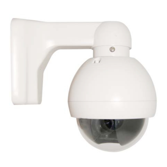
- Page 1 INSTALLATION MANUAL ST-WD600PTZMINI Vandalproof Intelligent Dome PTZ Color Camera v2.2 7/28/11...
-
Page 2: Package Contents
This package contains: One ST-WD600PTZMINI vandalproof intelligent dome color camera One installation manual Note: The ST-WD600PTZMINI requires a minimum 12VDC 500mA power supply such as the ST-PS12VDC1A or ST-PS12VDC2A. PRODUCT DESCRIPTION The ST-WD600PTZMINI is a professional grade IP66-rated outdoor dome color camera with pan, tilt and zoom (PTZ) capability of 600TVL of resolution. -
Page 3: Unpacking And Handling
INSTALLATION AND OPERATION This symbol is intended to alert the user to the presence of important operating and maintenance (servicing) instructions. This symbol is intended to alert the user to the presence of uninsulated “dangerous voltage” within the product’s enclosure that may be of sufficient magnitude to constitute a risk of electrical shock. -
Page 4: Wiring Connections
4. WIRING CONNECTIONS a. Connect the power supply’s DC plug to the camera’s power outlet. b. Connect the camera to the monitor with a 75Ω coaxial video cable. c. Connect unshielded twisted pair (UTP) control cable between the camera’s RS485 port and the PTZ controller. - Page 5 5. SETTING CAMERA ADDRESS, PROTOCOL and BAUD RATE USING DIP-SWITCHES Camera address, protocol and baud rate can be set using the camera’s OSD menus and a PTZ controller connected to the camera or using the camera’s onboard DIP-switches. To use the camera’s DIP-switches, open the camera’s top cover.
- Page 6 6. SETTINGS USING CAMERA’s ON SCREEN DISPLAY MENU v2.2 7/28/11...
- Page 7 7. FUNCTIONS The camera uses preset commands to achieve a number of functions. CLEAR / SET / GOTO and the preset number to perform these functions. Set Preset Point Numbers: Preset No. Function 1 – 32 Set Preset Point Set Left Limited Point Set Right Limited Point Set Home Point Set Home Point Wait Time to 64...
-
Page 8: Troubleshooting
To Set and Run a Pattern: a. Input SET preset 242 to begin pattern learning. b. Send GOTO preset command so the camera will recognize this point as a pattern point. For example, if the camera is to tour at point 1, 3, and 6 input GOTO preset point 1, GOTO preset point 3 and GOTO preset point 1.
Need help?
Do you have a question about the ST-WD600PTZMINI and is the answer not in the manual?
Questions and answers