Table of Contents
Advertisement
Quick Links
Advertisement
Table of Contents

Related Manuals for AIC SB201-VG


Summary of Contents for AIC SB201-VG
- Page 1 SB201-VG Storage Server Barebone User's Manual UM_SB201-VG_v1.2_062419...
-
Page 2: Table Of Contents
Table of Contents Preface ������������������������������������������������������������������������������������������������� i Safety Instructions ������������������������������������������������������������������������������ ii About This Manual ������������������������������������������������������������������������������ iv Chapter 1� Product Features �������������������������������������������������������������� 1 1.1 Box Contents ................... 1 1.2 Specifications ..................2 1.3 Feature ..................... 3 Chapter 2� Hardware Setup ���������������������������������������������������������������� 6 2.1 Central Processing Unit Setup ............... - Page 3 Chapter 4. BIOS Configuration Settings ������������������������������������������� 41 4.1 Navigation Keys ..................41 4.2 BIOS Setup .....................42 4.2.1 Menu ......................... 42 4.2.2 Startup ......................42 4.3 Main .......................45 4.3.1 Main ........................45 4.4 Advanced ....................46 4.4.1 Peripheral Configuration ................. 46 4.4.2 Video Configuration ..................46 4.4.3 Socket Configuration ..................
- Page 4 Copyright © 2018 AIC, Inc� All Rights Reserved� This document contains proprietary information about AIC products and is not to be disclosed or used except in accordance with applicable agreements.
- Page 5 Document Release History Release Date Version Update Content January User's Manual release to public. 2018 Febuary Content update 2019 June New cover 2019...
-
Page 6: Preface
Disclaimer AIC shall not be liable for technical or editorial errors or omissions contained herein. The information provided is provided "as is" without warranty of any kind. To the extent permitted by law, neither AIC or its affiliates, subcontractors or suppliers will be liable for incidental, special or consequential damages including downtime cost;... -
Page 7: Safety Instructions
Safety Instructions Before getting started, please read the following important cautions: • All cautions and warnings on the equipment or in the manuals should be noted. • Most electronic components are sensitive to electrical static discharge. Therefore, be sure to ground yourself at all times when installing the internal components. •... - Page 8 • If one of the following situations arise, the equipment should be checked by service personnel: 1. The power cord or plug is damaged. 2. Liquid has penetrated the equipment. 3. The equipment has been exposed to moisture. 4. The equipment does not work well or will not work according to its user manual. 5.
-
Page 9: About This Manual
This document pellucidly presents a brief overview of the product design, device installation, and firmware settings for SB201-VG. For the latest version of this user's manual, please refer to the AIC website: https://www.aicipc.com/en/productdetail/20884. -
Page 10: Chapter 1� Product Features
Chapter 1. Product Features SB201-VG User Manual Chapter 1. Product Features SB201-VG is a high density storage server that includes mother board, chassis, power supply, and HDD backplane. For more information about our product, please visit our website at http://www.aicipc.com/en. -
Page 11: 1.2 Specifications
SB201-VG User Manual Chapter 1. Product Features 1.2 Specifications mm : 430 x 646.2 x 88.2 • 2 x16 slots (LP) Dimensions Expansion Slots PCIe 3.0 • 3 x8 slots (LP) (W x D x H) inches : 17 x 25.4 x 3.5... -
Page 12: Feature
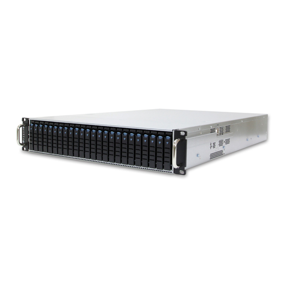
Chapter 1. Product Features 1�3 Feature SB201-VG is a reliable 2U storage server barebone with 24 hot swap drives bays at the front and two 7mm at the rear. This product is designed to accommodate the serverboard, Virgo, which supports Intel® C620 PCH chipset and 12 DDR4 2400/2666Mhz EEC UDIMM to offer greater perfomance, efficiency, and utility for our customers. - Page 13 SB201-VG User Manual Chapter 1. Product Features Front Panel 2.5-inch hot swap drive bay System LED Indicator and Switch Item Description Power Button System Power LED Drive Activity LED System ID LED System Reset Button Rear Panel ...
- Page 14 SB201-VG User Manual Chapter 1. Product Features Top View Item Description Virgo Motherboard 3 x 80 x 38mm system fans...
-
Page 15: Chapter 2� Hardware Setup
Chapter 2� Hardware Setup Chapter 2. Hardware Setup SB201-VG User Manual This chapter provides the graphic detail and basic instruction for hardware installation. Turn off the system and unplug all peripheral devices before proceeding. 2�1 Central Processing Unit Setup The serverboard supports dual Xeon scalable processors and Socket P0 (LGA-3647). - Page 16 SB201-VG User Manual Chapter 2. Hardware Setup Processor Socket Assembly: The server board includes two processor sockets (LGA-3647), supports one or two of the Intel® Xeon® Processor Scalable Family and has a Thermal Design Power (TDP) of up to 165W on selected models.
- Page 17 Chapter 2. Hardware Setup SB201-VG User Manual PHM Screw Installation Order: The PHM sits level with the processor socket assembly. The PHM is NOT installed properly if it does not sit level with the processor socket assembly. Once the PHM is seated over the processor socket assembly, the four heat sink torque screws must be secured in the following order as shown below.
-
Page 18: Cpu Heatsink
SB201-VG User Manual Chapter 2. Hardware Setup 2�1�2 CPU heatsink CAUTION There may be possible thermal during physical contact with the heatsink. Avoid moving the heatsink after it has contacted the top of the CPU. Too much movement could disturb the layer of thermal compound, causing voids and leading to ineffective heat dissipation and component damage. -
Page 19: System Memory
Chapter 2. Hardware Setup SB201-VG User Manual 2�2 System Memory 2�2�1 DIMM Installation Unlock the DIMM socket by pressing the retaining clips outward. Insert the memory module into the slot. Make sure that the DIMM notch is accurately positioned. -
Page 20: Dimm Installation Order
SB201-VG User Manual Chapter 2. Hardware Setup 2�2�2 DIMM Installation Order JDIMML0 JDIMMC0 JDIMMK0 JDIMMB0 JDIMMJ0 JDIMMA0 DIMM Numbers DIMM ARRANGMENT CPU 0 CPU 0 CPU 1 CPU 1 CPU1 CPU0 2 DIMMs JDIMM_L0 JDIMM_C0 JDIMMG0 JDIMMD0 JDIMMH0 JDIMME0 JDIMMI0... - Page 21 Chapter 2. Hardware Setup SB201-VG User Manual JDIMML0 JDIMMC0 JDIMMK0 JDIMMB0 JDIMMJ0 JDIMMA0 CPU1 CPU0 JDIMM_L0 JDIMM_C0 CPU 0 CPU 0 CPU 1 CPU 1 JDIMM_K0 JDIMM_B0 10 DIMMs JDIMM_J0 JDIMM_A0 JDIMM_G0 JDIMM_D0 JDIMMG0 JDIMMD0 JDIMM_I0 JDIMM_F0 JDIMMH0 JDIMME0 JDIMMI0...
-
Page 22: Top Cover
SB201-VG User Manual Chapter 2. Hardware Setup 2�3 Top Cover Push the release button on both sides of the chassis and push the cover towards the rear panel. Lift the top cover upward to complete removal. ... -
Page 23: Power Supply Unit Module
Chapter 2. Hardware Setup SB201-VG User Manual 2�4 Power Supply Unit Module Extract the power supply unit by pushing the ejector while pulling the power supply unit. Pull the module completely out of the chassis. Install the new power supply unit by pushing it into the chassis. Ensure that the ... -
Page 24: Fan Module
SB201-VG User Manual Chapter 2. Hardware Setup 2�5 Fan Module Unplug the cables and connectors. Lift the fan module upward. Check to carefully dislodge the rubber connectors from the attached bracket. Insert the new fan into the chassis. Verify to align the rubber connectors ... -
Page 25: Hard Disk Drive
Chapter 2. Hardware Setup SB201-VG User Manual 2�6 Hard Disk Drive Press the release button on the tray lever to loosen the lever. Pull the tray lever outward completely. Pull the tray out of the chassis. ... - Page 26 SB201-VG User Manual Chapter 2. Hardware Setup Insert the disk drive into the tray. Ensure that the dimples on the tray match the disk drive. For additional security, fasten the screws x 4 on the drive tray to lock the disk drive.
-
Page 27: Hdd Backplane Module
Chapter 2. Hardware Setup SB201-VG User Manual 2�7 HDD Backplane Module Detach the cables and hard disk drives from the backplane module. Release the module by shifting the hook. Dislodge the screws on the module. Lift the module upward to remove. -
Page 28: Slide Rail Installation
SB201-VG User Manual Chapter 2. Hardware Setup 2�8 Slide Rail Installation NOTE This sections provides a basic instruction for mounting the slide rail onto the system. Tool-less rails vary per order. The rail in this manaul may not exactly match the rail for your system. - Page 29 Chapter 2. Hardware Setup SB201-VG User Manual Install the inner rail onto the system barebone. Lock the keyholes and secure the screws on sides of the system. Keyhole screw Continue installing the outer rail bracket to the mounting frame. Attach the outer ...
- Page 30 SB201-VG User Manual Chapter 2. Hardware Setup Pull out the middle channel until the ball bearing retainer is locked forward. NOTE Verify ball bearing retainer is locked forward. Slide the release tab and push barebone into rack. Make sure the barebone is ...
-
Page 31: Chapter 3� Hardware Settings
Chapter 3� Hardware Settings SB201-VG User Manual Chapter 3. Hardware Settings This section describes the jumpers, internal connectors and internal LEDs setting in the system barebone. 3�1 Motherboard Block Diagram Platform Environment Control Interface(PECI) DIMM #H0 DIMM #J0 DIMM #L0... -
Page 32: Motherboard Content List
SB201-VG User Manual Chapter 3. Hardware Settings 3�2 Motherboard Content List Connector/Jumper/Header Location Connector/Jumper/Header Location Power Supply JPWR1, JPWR3, Front I/O USB Header JUSB_INT Connector JPWR4 Power Supply JPWR2 SSI Front Panel Header JFRNT_SSI Connector External Thermal J2, J13, J24... -
Page 33: Motherboard Layout
SB201-VG User Manual Chapter 3. Hardware Settings 3�3 Motherboard Layout CPU1 CPU1 CPU0 CPU0 CPU0 19 18... -
Page 34: Connector And Jumper
SB201-VG User Manual Chapter 3. Hardware Settings 3�4 Connector and Jumper 3�4�1 Connector 6 SAS IOC Activity LED Header (J19) 1 Power Connector +3.3V (JPWR1, JPWR3 & JPWR4) SAS_LED_GPIO16 SAS_LED_GPIO20 SAS_LED_GPIO17 SAS_LED_GPIO21 SAS_LED_GPIO18 SAS_LED_GPIO22 SAS_LED_GPIO19 SAS_LED_GPIO23 7 SAS IOC Error LED Header (J25) 2 Power Connector (JPWR2) +3.3V... - Page 35 SB201-VG User Manual Chapter 3. Hardware Settings SFF-8643 Connector for PCIe (CN1) SFF-8643 Connector for PCIe (CN4) SMBDAT_MUX_6 C1 A1 CLK_100M_SSD6_P SMBDAT_MUX_4 C1 A1 CLK_100M_SSD4_P SMBCLK_MUX_6 C2 A2 CLK_100M_SSD6_N SMBCLK_MUX_4 C2 A2 CLK_100M_SSD4_N C3 A3 GND C3 A3 GND CPU1_EXP1_TX_DP_13 C4 A4 CPU1_EXP1_RX_DP_13...
- Page 36 SB201-VG User Manual Chapter 3. Hardware Settings SFF-8643 connector for SAS (CN7) SIO1_SAS_DOUT C1 A1 N.C. C2 A2 SIO1_SAS_CLK C3 A3 GND SAS_EXP_TX_P6 C4 A4 SAS_EXP_RX_P6 SAS_EXP_TX_N6 C5 A5 SAS_EXP_RX_N6 C6 A6 GND SAS_EXP_TX_P7 C7 A7 SAS_EXP_RX_P7 SAS_EXP_TX_N7 C8 A8 SAS_EXP_RX_N7...
- Page 37 SB201-VG User Manual Chapter 3. Hardware Settings 15 PCH SSGPIO Header (JSSGPIO) 27 Front I/O USB Header (JUSB_INT) 17 PCH GPIO Header (JPCH_GPIO) 28 SSI Front Panel Header (JFRNT_SSI) 24 SAS IOC ICE Header (J12)
- Page 38 SB201-VG User Manual Chapter 3. Hardware Settings 32 EPSI Header (JEPSI) 34 PCIE Hot-Plug SMB Header (JPCIE_HP) 33 Debug Port Header (JLPC_DP) 35 PCIE Hot-Plug Front Panel Header (J4, J5, & J6)
- Page 39 SB201-VG User Manual Chapter 3. Hardware Settings 38 Front COM Header (JCOM1 & JCOM4) 42 BMC Debug Port Header (JBMC_DP) 39 VROC KEY Header (JRAID_KEY) 44 BMC I2C1 header (JBMC_I2C1) I2C1SCL I2C1SDA 40 LCM Header (JLCM) 45 BMC GPIO header (JBMC_GPIO)
-
Page 40: Jumper
SB201-VG User Manual Chapter 3. Hardware Settings 3�4�2 Jumper SATA4 Pin-7 Power Header (J10) 26 No Reboot(Watch Dog) Jumper (J26) Setting J26 (No Reboot) Setting Short SATA4 pin-7 Power Short Enable Open Normal Default Open Disable Default 36 ME Force Recovery Mode Jumper (J3) -
Page 41: System Led Indicator
SB201-VG User Manual Chapter 3. Hardware Settings 3�5 System LED Indicator 3�5�1 Front Panel LED Yellow The system is On. The system is in Standby; System is off, but Power Blinking has AC power. System has no AC power Blue UID activity is detected. -
Page 42: Internal Led
SB201-VG User Manual Chapter 3. Hardware Settings 3�5�3 Internal LED LAN2 10G LED LAN1 10G LED SFP+ LAN1 1G LED LAN2 1G LED LAN4 1G/10G LED LAN3 1G/10G LED BMC Heart Beat LED SAS IOC Status LED NVME Hot-Plug LED... - Page 43 SB201-VG User Manual Chapter 3. Hardware Settings 3�6 HDD Backplane 3�6�1 Connector Location Connector Location JFAN4 JFAN2 JFAN1 JPWR1 JFAN3 JPWR2 JPMBUS JEXP2 JEXP_UART JFRONT Sensor Sensor Sensor Sensor JMCU_UART JMCU_UART JI2C0 SASHD1 JI2C3 JMCU_DBG SASHD3 JI2C4 SASHD2 HDD1 HDD24...
- Page 44 SB201-VG User Manual Chapter 3. Hardware Settings 3�6�2 Connector Power Connector (JPWR1) Description Description +12V +12V VCC3 MUTE_L +5VSTBY PSU_N1 PS_ON_L Power Connector (JPWR2) Description Description +12V +12V +12V +12V PMBUS Connector (JPMBUS) Description PMBUS_CLOCK PMBUS_DATA...
- Page 45 SB201-VG User Manual Chapter 3. Hardware Settings FAN Connector (JFAN 1~ JFAN4) Description +12V TACH Cascade (JEXP2) Description Description E2E_SCL E2E_SCL E2E_SDA E2E_SDA PEER_MATE_N LB_AB0 LB_BA0 LB_AB1 LB_BA1 Control for Expander (JEXP_UART) Description Description DBG_SIRXD SM_SIRXD DBG_SITXD SM_SITXD...
- Page 46 SB201-VG User Manual Chapter 3. Hardware Settings Console for MCU (JMCU_DBG) Description UART_RX UART_TX Remote Power Control (JMCU_UART) Description Description DOWN_RXD UP_RXD DOWN_TXD UP_TXD I2C Connectort (JI2C0,JI2C3 & JI2C4) Description I2C_CLOCK I2C_DATA...
- Page 47 SB201-VG User Manual Chapter 3. Hardware Settings 2.54mm Header for Front I/O (JFRONT) Fan number select Pin[5,6] Pin [3,4] Pin [1,2] Fan no� support Active Fan Locate Close Close Close No fan Close Close Open 1 Fan JFAN1 Close Open...
- Page 48 SB201-VG User Manual Chapter 3. Hardware Settings Power/ID LED Description Remark For External LED(+) LED Anode For External LED(-) LED Cathode Power SW Description Remark Power SW Input(-) Active Low PMBUS Support Description Remark PMBUS_Disable_N Active Low 3�6�3 Jumper Open...
- Page 49 SB201-VG User Manual Chapter 3. Hardware Settings 3�6�4 LED Indicator Expander alive, 0.833Hz Expander Blink (LED2) Blue (Blinking) (12 seconds per cycle) Expander Heart Beat (LED1) Blue (Blinking) Expander FW running Blue (On) HDD present HDD Activity LEDs Blue (Blinking)
-
Page 50: Chapter 4. Bios Configuration Settings
Chapter 4. BIOS Configuration Settings SB201-VG User Manual Chapter 4. BIOS Configuration Settings 4�1 Navigation Keys The navigation keys are listed below. Function Key Description Select item. , , , Enter Select and enter sub-screen. + , - Modify selected option. -
Page 51: Bios Setup
SB201-VG User Manual Chapter 4. BIOS Configuration Settings 4�2 BIOS Setup 4�2�1 Menu Press and to select the options of the menu bar. Press Enter to access the option screen. Menu Description Main Displays basic system information and date & time. - Page 52 SB201-VG User Manual Chapter 4. BIOS Configuration Settings Step 2 There will be a message “Entering SETUP” displayed on the diagnostics screen. Step 3 Identify the BIOS version. NOTE For the official released version, the last digit of the BIOS version must end in a “0.“...
- Page 53 SB201-VG User Manual Chapter 4. BIOS Configuration Settings Step 4 Load Optimal Default Setting. Step 5 Save the setting and exit the BIOS setup utility.
-
Page 54: Main
SB201-VG User Manual Chapter 4. BIOS Configuration Settings 4�3 Main Main Option Key: 4�3�1 Main Option Key Description System time Configures the current time. System date Configures the current date. -
Page 55: Advanced
SB201-VG User Manual Chapter 4. BIOS Configuration Settings 4�4 Advanced Advanced Option Key: 4.4.1 Peripheral Configuration Peripheral Configuration PCIe SR-IOV Enable Disable PCIe ARI Enable Disable ARI Forward Enable Disable Spread Enable Disable Spectrum Redfish On/ Enable Disable 4.4.2 Video Configuration... - Page 56 SB201-VG User Manual Chapter 4. BIOS Configuration Settings MSR Lock Control Enable Disable Processor Configuration Extended APIC Enable Disable 128M 256M MMCFG Size 512M Common MMIO High Base RefCode Configuration MMIO High Granularity Size 256G 1024G Disable Minimum Serial Debug Message...
- Page 57 SB201-VG User Manual Chapter 4. BIOS Configuration Settings Check Platform Detect Enable Disable Erase-Arm NVDIMMs Enable Disable Restore NVDIMMs Enable Disable Memory Configuration Interleave NVDIMMs Enable Disable Custom Refresh Rate Min=0, Max=40 Auto 100 KHz SMB Clock Frequency 400 KHz...
- Page 58 SB201-VG User Manual Chapter 4. BIOS Configuration Settings Single Power Enable Disable Domain (SPD) Max Performance Boot performance Max Efficient mode Set by Intel Node Manager CPU P State Control Energy Enable Disable Efficient Turbo Turbo Mode Enable Disable CPU Flex Ratio...
-
Page 59: 4.4.4 Pch Configuration
SB201-VG User Manual Chapter 4. BIOS Configuration Settings 4.4.4 PCH Configuration PCH Configuration PCH Devices PCH state after G3 Last State SATA Controller Configure SATA as AHCI RAID Support Aggressive Link Power Enable Disable Management Alternate Device ID on Enable... - Page 60 SB201-VG User Manual Chapter 4. BIOS Configuration Settings Smart Response Enable Disable Technology PCH SATA Configuration 2 Seconds 4 Seconds RAID OROM prompt delay 6 Seconds 8 Seconds sSATA Controller Enable Disable Configure sSATA as AHCI RAID Support Aggressive Link Power...
- Page 61 SB201-VG User Manual Chapter 4. BIOS Configuration Settings SLP_LAN# Low on DC Enable Disable Power K1 off Enable Disable FPK Port 1-4 Enable Management Disable PCI Delay Enable Disable Optimization Compliance Test Enable Disable Mode PCI-E ASPM Support Per individual port...
- Page 62 SB201-VG User Manual Chapter 4. BIOS Configuration Settings Enable Disable Enable Disable Enable Disable NFER Enable Disable Enable Disable SEFE Enable Disable SENFE Enable Disable SECE Enable Disable PME SCI Enable Disable Hot Plug Enable Disable Advanced Error Enable Disable...
-
Page 63: 4.4.5 H2O Ipmi Configuration
SB201-VG User Manual Chapter 4. BIOS Configuration Settings Auto Non Snoop Latency Manual Override Disable Non Snoop Min=0, Max=102 Latency Value PCH sSATA PCH PCIe LTR Configuration Configuration 1 ns 32 ns Non Snoop Latency 1024 ns 32768 ns Multiplier... -
Page 64: H2O Event Log Config Manager
SB201-VG User Manual Chapter 4. BIOS Configuration Settings 4.4.6 H2o Event Log Config Manager H2o Event Log Config Manager Console Serial Enable Disable Redirect VT_100 VT_100+ Terminal Type VT_UTF8 PC_ANSI 1200 2400 4800 9600 Baud Rate 19200 38400 57600 115200... -
Page 65: Security
SB201-VG User Manual Chapter 4. BIOS Configuration Settings 4�5 Security Security Option Key: 4�5�1 Security Security Current TPM Not Detected TPM 1.2 TPM 2.0 Device TrEE Protocol Version Available Hidden Availability Disable and No operation Enable and Activate Operation Deactivate... -
Page 66: Power
SB201-VG User Manual Chapter 4. BIOS Configuration Settings 4�6 Power Power Option Key: 4�6�1 Power Power Wake on PME Enable Disable... -
Page 67: Boot
SB201-VG User Manual Chapter 4. BIOS Configuration Settings 4�7 Boot Boot Option Key: 4�7�1 Boot Boot Boot Type Dual Boot Type Legacy Boot Type UEFI Boot Type Quick Boot Enable Disable Quiet Boot Enable Disable Network Enable Disable Stack PXE Boot to... -
Page 68: Exit
SB201-VG User Manual Chapter 4. BIOS Configuration Settings 4�8 Exit Exit Option Key: 4�8�1 Exit Save and Exit Exit Saving Changes Exit system setup and save your changes. Save Change Without Save your changes without exiting the system. Exit Exit Discarding Discard your changes when existing the system. -
Page 69: Chapter 5. Bmc Configuration Settings
Chapter 5. BMC Configuration Settings Spica User Manual SB201-VG User Manual Chapter 5. BMC Configuration Settings Insert Ethernet LAN cable into the BMC LAN port. BMC management port (Dedicated NIC channel 1 ) 2 x 10GbE SFP+ (Shared NIC channel 8) 5�1 Network Settings... - Page 70 SB201-VG User Manual Chapter 5. BMC Configuration Settings...
- Page 71 SB201-VG User Manual Chapter 5. BMC Configuration Settings Step 3 Input the subnet mask address.
-
Page 72: Web Gui
SB201-VG User Manual Chapter 5. BMC Configuration Settings 5�2 Web GUI The IP address below is an example using the default IP setting. The IP address is configurable. Step 1 Open the browser then type default BMC IP address: 192.168.22.22 Step 2 Use the default user name and password for first-time login to BMC WEB GUI. - Page 73 SB201-VG User Manual Chapter 5. BMC Configuration Settings Dashboard: The Dashboard page gives the overall information about the status of a device. Server Health - Sensor Readings: Then Sensors Readings page displays all the sensor related information. Settings: The Settings page allows you to access various configuration settings.
- Page 74 SB201-VG User Manual Chapter 5. BMC Configuration Settings KVM Mouse Setting: The KVM Mouse Setting page displays the setting for mouse emulation from local window to remote screen. • For Windows OS environment, set mode to absolute. • For Linux OS environment, set mode to relative.
- Page 75 SB201-VG User Manual Chapter 5. BMC Configuration Settings Environmental setting:...
-
Page 76: Chapter 6� Technical Support
Chapter 6� Technical Support SB201-VG User Manual Chapter 5. BMC Configuration Settings Taiwain, Global Headquarters South California, United States Address: No� 152, Section 4, Address: 21808 Garcia Lane Linghang N� Rd, Dayuan District, City of Industry, CA 91789, Taoyuan City 337, Taiwan...
Need help?
Do you have a question about the SB201-VG and is the answer not in the manual?
Questions and answers