Table of Contents
Advertisement
Quick Links
Advertisement
Table of Contents

Related Manuals for Isuzu C-240PW-28


Summary of Contents for Isuzu C-240PW-28
- Page 1 ARMY TM 9-2815-254-24 AIR FORCE TO 38G1-94-2 TECHNICAL MANUAL UNIT, DIRECT SUPPORT GENERAL SUPPORT MAINTENANCE INSTRUCTIONS DIESEL ENGINE MODEL C-240PW-28 4 CYLINDER 2.4 LITER NSN: 2815-01-350-2207 HEADQUARTERS, DEPARTMENTS OF THE ARMY AND THE AIR FORCE 1 SEPTEMBER 1993...
- Page 3 ARMY TM 9-2815-254-24 AIR FORCE TO 38G1-94-2 SAFETY SUMMARY For first aid, refer to FM21-11. The noise level when operating could cause hearing damage. Ear protection must be worn. Where applicable, prior to performing engine maintenance, ensure bat- teries are disconnected. Do not drain coolant until the coolant temperature is below operating temperature.
- Page 5 WASHINGTON, D.C., 30 October 1996 No.2 Unit, Direct Support and GeneraI Support Maintenance lnstructions DIESEL ENGINE MODEL C-240PW-28 4 CYLINDER 2.4 LITER NSN: 2815-01-350-2207 DISTRIBUTION STATEMENT A: Approved for public release; distribution is unlimited TM 9-2815-254-24/TO 38G1-94-2, 1 September 1993, is changed as follows: 1.
- Page 6 ARMY TM 9-2815-254-24 AIR FORCE TO 38G1-94-2 By Order of the Secretaries of the Army and Air Force: DENNIS J. REIMER General, United States Army Official: Chief of Staff Administrative Assistant to the Secretary of the Army 02954 RONALD R. FOGELMAN General, USAF Chief of Staff HENRY VICCELLIO Jr.
- Page 7 TECHNICAL MANUAL UNIT, DIRECT SUPPORT AND GENERAL SUPPORT MAINTENANCE INSTRUCTIONS DIESEL ENGINE MODEL C-240PW-28 4 CYLINDER 2.4 LITER NSN: 2815-01-350-2207 DISTRIBUTION STATEMENT A; Approved for public release; distribution is unlimited. TM 9-2815-254-24/TO 39G1-94-2, 1 SEPTEMBER 1993 is changed as follows: 1.
- Page 8 ARMY TM 9-2815-254-24 AIR FORCE TO 38G1-94-2 By Order of the Secretaries of the Army and air Force GORDON R. SULLIVAN General, United States Army Chief of Staff MILTON H. HAMILTON Administrative Assistant to the Secretary of the Army 05829 MERRILL A.
- Page 9 ARMY TM 9-2815-254-24 AIR FORCE TO 38G1-94-2 HEADQUARTERS TECHNICAL MANUAL DEPARTMENTS OF THE ARMY AND THE AIR FORCE WASHINGTON, D.C., 1 September 1993 NO. 9-2815-254-24 Unit, Direct Support and General Support Maintenance Instructions DIESEL ENGINE MODEL C-24OPW-28 4 CYLINDER 2.4 LITER NSN: 2815-01-350-2207 REPORTING ERRORS AND RECOMMENDING IMPROVEMENTS You can help improve this manual.
-
Page 10: Table Of Contents
ARMY TM 9-2815-254-24 AIR FORCE TO 38G1-94-2 TABLE OF CONTENTS - Continued PREPARATION FOR USE ....... . Section III. -
Page 11: Table Of Contents
ARMY TM 9-2815-254-24 AIR FORCE TO 38G1-94-2 TABLE OF CONTENTS - Continued Section ENGINE BLOCK MAINTENANCE ..........3 - 9 9 Front Gear Cover . -
Page 12: Table Of Contents
ARMY TM 9-2815-254-24 AIR FORCE TO 36G1-94-2 Engine Components ........... . 3-16 Thermostat and Housing . -
Page 13: Table Of Contents
ARMY TM 9-2815-254-24 AIR FORCE TO 38G1-94-2 LIST OF ILLUSTRATIONS - Continued Oil Pressure Test Setup ............3-78 3-43 PCV Assembly . -
Page 14: Table Of Contents
ARMY TM 9-2815-254-24 AIR FORCE TO 33G1-94-2 LIST OF ILLUSTRATIONS - Continued Page ........3-137 Crankshaft Journal and Crankpin Diameter 3-87... - Page 15 ARMY TM 9-2815-254-24 AIR FORCE TO 38G1-94-2 LIST OF TABLES Table of Specifications ............Preventive Maintenance Checks and Services (PMCS) .
- Page 17 ARMY TM 9-2815-254-24 AIR FORCE TO 38G1-94-2 CHAPTER 1 INTRODUCTION SECTION I. GENERAL INFORMATION 1-1. SCOPE. 1-1.1. Type of Manual. This manual contains unit, direct support, and general support maintenance instructions for the Model C240 Diesel Engine, hereafter referred to as engine. Also included are descriptions of major systems/corn- ponents and their functions in relation to other systems/components.
- Page 18 ARMY TM 9-2815-254-24 AIR FORCE TO 38G1-94-2 1-4. DESTRUCTION OF ARMY MATERIAL TO PREVENT USE. Refer to TM 750-244-3 for procedures to destroy equipment to prevent enemy use. 1-5. Refer to TB 740-97-2 for procedures to place the equipment into storage. 1-6.
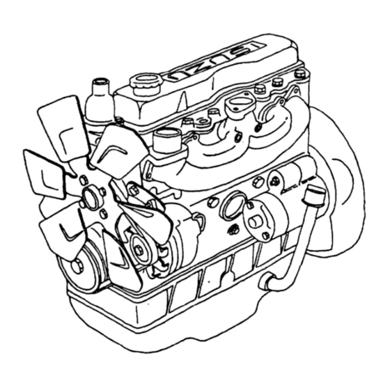
- Page 19 ARMY TM 9-2815-254-24 AIR FORCE TO 38G1-94-2 SECTION II. EQUIPMENT DESCRIPTION AND DATA 1-7. GENERAL. The diesel engine (FIGURE 1-1) is four cylinder, four cycle, fuel injected, naturally-aspirated, and liquid-cooled. The firing order is 1-3-4-2. The number one cylinder is toward the fan end of the engine. The serial number is found on left side of the cylinder body at number one cylinder location.
-
Page 20: Engine Components
ARMY TM 9-2815-254-24 AIR FORCE TO 38G1-94-2 Fan Belt Fan Pulley Fuel Pipes Fuel Injector Pipes Injector Nozzle and Glow Plug Oil Filter Fuel Filter Housing PCV Valve Crankshaft Pulley Battery Charging Alternator Starter Intake Manifold Exhaust Manifold Valve cover Thermostat Housing Water Pump Oil Pan... - Page 21 ARMY TM 9-2815-254-24 AIR FORCE TO 38G1-94-2 1-9. EQUlPMENT DATA. 1-9.1. Leading Particulars. For a list of leading particulars, refer to TABLE 1-1. TABLE 1-1. Table of Specifications lsuzu, C240 PW-28 Model ............. Type .
-
Page 22: Section Iii. Preparation For Use
ARMY TM 9-2815-254-24 AIR FORCE TO 38G1-94-2 SECTION III. PREPARATION FOR USE 1-10. lNSPECTlNG AND SERVlCING ENGINE. This section provides information and guidance for inspecting, servicing, and installing the engine. For additional information, also refer to end item maintenance manual. 1-10.1. -
Page 23: Chapter 2 Operation
ARMY TM 9-2815-254-24 AIR FORCE TO 38G1-94-2 CHAPTER 2 OPERATION SECTION I. PRINCIPLES OF OPERATION 2-1. INTRODUCTIONS This section contains functional descriptions of the engine systems and how they are connected to the end item 2-2. COOLING SYSTEM. The cooling system consists of a radiator, hoses, thermostat, belt driven fan, water pump, and cooling jackets within the engine. -
Page 24: Electrical System
ARMY TM 9-2815-254-24 AIR FORCE TO 38G1-94-2 2-4.2. Extremely cold outside temperatures make starting the engine difficult. To improve engine starting, a cold weather starting aid has been provided that features a glow plug for each cylinder. The glow plugs are energized to preheat engine combustion air during engine preheat starting cycle. - Page 25 ARMY TM 9-2815-254-24 AIR FORCE TO 38G1-94-2 SECTION II. OPERATING INSTRUCTIONS NOTE Refer to end item operator’s manual. 2-3/(2-4 blank)
-
Page 27: Chapter 3 Maintenance
ARMY TM 9-2815-254-24 AIR FORCE TO 38G1-94-2 CHAPTER 3 MAINTENANCE Section I. PREVENTIVE MAINTENANCE CHECKS AND SERVICES (PMCS) 3-1. PMCS PROCEDURES. 3-1.1. General. To ensure that engine is ready for operation at all times, it must be inspected so defects can be discovered Perform operator’s PMCS prior to or in and corrected before they result in serious damage or failure. - Page 28 ARMY TM 9-2815-284-24 AIR FORCE TO 38G1-94-2 Table 3-1. Preventive Maintenance Checks and Services (PMCS) - Continued Item Equipment is Procedures Check Interval for and have Not/Ready Item repaired or adjusted Available to be as necessary Inspected Remove, clean, and 3000 Engine Fuel test injectors.
-
Page 29: Troubleshooting Procedures
ARMY TM 9-2815-254-24 AIR FORCE TO 38G1-94-2 SECTION II. TROUBLESHOOTlNG 3-2. TROUBLESHOOTING PROCEDURES. 3-2.1. Purpose of Troubleshooting Table. This section contains troubleshooting information for locating and Correcting operating troubles which may develop in the engine. Each malfunction for an individual component unit or system is followed by a list of tests or inspections which will help you to determine probable causes and corrective action to take. - Page 30 ARMY TM 9-2815-254-24 AIR FORCE TO 38G1-94-2 TABLE 3-2 Troubleshooting ENGINE WILL NOT CRANK Check for defective end item starting system. Step 1. Troubleshooting per end item maintenance manual. lf not defective, do step 2. Check for defective starter motor and solenoid. Step 2.
- Page 31 ARMY TM 9-2815-254-24 AIR FORCE TO 38G1-94-2 Table 3-2. Troubleshooting - Continued MALFUNCTION TEST OR INSPECTION CORRECTIVE ACTION ENGINE HARD TO START OR WILL NOT START IN COLD WEATHER. step 1. Check for faulty glow plugs. a. Test glow plugs. Refer to paragraph 3-22.3. If glow plugs not defective, do step 2. Replace defective glow plugs.
- Page 32 ARMY TM 9-2815-254-24 AIR FORCE TO 38G1-94-2 Table 3-2. Troubleshooting - Continued MALFUNCTION TEST OR INSPECTION CORRECTIVE ACTION Check for low engine compression. Step 8. Perform engine compression check. Refer to paragraph 3-27.7. If engine defective, repair or replace engine. ENGINE DOES NOT DEVELOP FULL POWER.
- Page 33 ARMY TM 9-2815-254-24 AIR FORCE TO 38G1-94-2 Table 3-2. Troubleshooting - Continued MALFUNCTION TEST OR INSPECTION CORRECTIVE ACTION LOW OIL PRESSURE. Step 1. Check for improper grade of oil. Refer to end item lubrication order. If proper grade of oil, do step 2. If improper grade of oil, refer to end item maintenance manual and change oil and filter.
- Page 34 ARMY TM 9-2815-254-24 AIR FORCE TO 38G1-94-2 Table 3-2. Troubleshooting - Continued MALFUNCTION TEST OR INSPECTION CORRECTIVE ACTION Step 5. Defective fuel injection pump. Remove and test fuel injection pump. Refer to paragraph 3-11.5. If fuel injection pump not defective, go to step 6. Replace fuel injection pump.
- Page 35 ARMY TM 9-2815-254-24 AlR FORCE TO 38G1-94-2 Table 3-2 Troubleshooting - Continued MALFUNCTION TEST OR INSPECTION CORRECTIVE ACTlON ENGlNE KNOCKS. Step 1. lmproper fuel injection pump timing. Check fuel injection pump timig. Refer to paragraph 3-13.1. lf fuel injection timing is correct, do step 2.
- Page 36 ARMY TM 9-2815-254-24 AIR FORCE TO 30G1-94-2 Table 3-2. Troubleshooting - Continued MALFUNCTION TEST OR INSPECTION CORRECTIVE ACTION ENGINE MAKES A GAS LEAKING NOISE. Check for loose or damaged exhaust manifold. Step 1. a. Inspect for damaged and attaching hardware. IF not damage or loose, do step 2. b.
- Page 37 ARMY TM 9-2815-254-24 AlR FORCE TO 38G1-94-2 Table 3-2. Troubleshooting - Continued BATTERY CHARGED AMMETER SHOWS EXCESSIVE CHARGING AFTER PROLONGED PERIOD. Check for defective batteries. Step 1. Test batteries. Refer to end item maintenance manual. If batteries not defective, do step 2. b.
-
Page 38: General
ARMY TM 9-2815-254-24 AIRFORCE TO 38G1-94-2 SECTION III. GENERAL MAINTENANCE 3 - 3 . GENERAL This section provides general maintenance not found in other sections of Chapter 3. 3 - 3 . 1 General Instructions. Where applicable, prior to performing engine maintenance, ensure bat- teries are disconnecting. - Page 39 ARMY TM 9-2815-254-24 AIR FORCE TO 38G1-94-2 3-4.1. Disassembly. If the engine has been operating and coolant is hot, allow engine to cool before you slowly loosen filler cap and relieve pressure from cooling system. Failure to observe this warning could result in severe personal injury.
- Page 40 ARMY TM 9-2815-254-24 AIR FORCE TO 38G1-94-2 m. Remove rocker arm cover and rocker arm assembly, refer to paragraph 3-26.1. Remove pushrods, cylinder head assembly and cylinder head gasket, refer to paragraph 3-27.1. Check for bent push rods and discard cylinder head gasket. Remove crank shaft pulley and front gear cover, refer to paragraph 3-25.1.
- Page 41 ARMY TM 9-2815-254-24 AIR FORCE TO 36G1-94-2 Install oil pan, refer to paragraph 3-17.3. Install cylinder head assembly and Push rods, refer to paragraph 3-27-6. install rocker arm assembly, refer to paragraph 3-26.5. install intake and exhaust manifolds, refer to paragraph 3-21.3. m.
-
Page 42: Section Iv. Cooling System Maintenance
ARMY TM 9-2815-254-24. AIR FORCE TO 38G1-94-2 SECTION IV. COOLING SYSTEM MAINTENANCE 3 - 5 . G E N E R A L . This section provides maintenance for cooling system components. Components of cooling system not men- tioned in this section can be found in the end item maintenance manual. 3-6. - Page 43 ARMY TM 9-2815-254-24 AIR FORCE TO 36G1-94-2 Remove two screws (1) securing outlet pipe (2) to housing (8); remove outlet pipe (2) and gasket (3). Discard gasket (3). Lift thermostat (4) from housing. Loosen two hose clamps (10) and remove bypass hose (11) from housing (8) and water pump housing. NOTE : Note location of two shorter screws (6) for use during installation.
-
Page 44: Water Pump
ARMY TM 9-2815-264-24 AIR FORCE TO 38G1-94-2 Apply sealing compound (FORMAGASKET2) and position outlet pipe (2) and new gasket (3) on housing (8) and secure with two screws (1). Tighten screws to 168 in-lbs (19 Nm). Install bypass hose (11) on housing (8) and water pump housing and secure with two hose clamps (10). Connect outlet hose to outlet pipe (2) and secure with hose clamp. - Page 45 ARMY TM 9-2815-254-24 AIR FORCE TO 36G1-94-2 3-7.2. Inspection. Inspect pump rotation for abnormal noise, binding, and other abnormal conditions. Inspect pump housing for cracks, corrosion, or any other damage. 3-7.3. Replacement. Replace pump assembly if inspection reveals any abnormal condition, such as bearing failure, ex- cessive end play, or abnormal rotation.
- Page 46 ARMY TM 9-2815-254-24 AIR FORCE TO 38G1-94-2 FIGURE 3-2. Water Pump 3-20...
-
Page 47: Section V. Fuel System Maintenance
ARMY TM 9-2815-254-24 AIR FORCE TO 38G1-94-2 SECTION V. FUEL SYSTEM MAINTENANCE 3 - 8 . G E N E R A L . This section provides maintenance for fuel system components. Components of the fuel system not mentioned in this section can be found in end item maintenance manual. - Page 48 ARMY TM 9-2815-254-24 AIR FORCE TO 38G1-94-2 Remove fluid passage bolt (7) securing fuel tube (9) to fluid passage bolt (7). Remove and discard two seals (8). Cap openings. Disconnect fuel return line (10) to facilitate removal of fluid passage bolt (11). Cap openings. Remove fluid passage bolt (11) securing fuel tube (13) to fitting on top of filter body (15).
-
Page 49: Fuel Filter Assembly
ARMY TM 9-2815-254-24 AIR FORCE TO 38G1-94-2 FIGURE 3-3. Fuel Filter Assembly 3-23... - Page 50 ARMY TM 9-2815-254-24 AIR FORCE TO 38G1-94-2 Position filter assembly on mounting bracket and secure filter body (15) with two bolts (14). Do not tighten bolts until fuel tubes have been connected to filter and tightened. Remove caps and install fuel return line (10). Attach fuel tube (13) to fitting on top of filter body (15) with two new seals (12) and fluid passage bolt (11).
- Page 51 ARMY TM 9-2815-254-24 AIR FORCE TO 38G1-94-2 Do not apply excessive force to injection fuel tubes. Failure to observe this caution could damage the equipment. NOTE Drain fuel into suitable container. Loosen sleeve nut on fuel tubes (1, 2, 3, and 4, FIGURE 3-4) at fuel injection pump Loosen sleeve nut on fuel tubes (1, 2, 3, and 4) at fuel injector.
- Page 52 ARMY TM 9-2815-254-24 AIR FORCE TO 38G1-94-2 FIGURE 3-4. Fuel lnjectors and Piping 3-26...
- Page 53 ARMY TM 9-2815-254-24 AIR FORCE TO 38G1-94-2 Remove retainer nut (20) and nozzle (21) from holder (25). If necessary, remove screw (22), connector (23), and gasket (24) from holder (25). Discard gasket (24). 3-10.3. Inspection. 3-10.3.1 Fuel Injector. The nozzle needle valve and nozzle body combinations must not be in- terchanged otherwise, injectors will not operate property.
- Page 54 ARMY TM 9-2815-254-24 AIR FORCE TO 38G1-94-2 3-10.4. Cleaning. Cleaning solvent is flammable and toxic to eyes, skin, and respiratory tract. Skin/eye protection required. Avoid repeated/prolonged contact. Good general ventilation is nom-rally adequate. Soak all parts except nozzle in a dry cleaning solvent (P-D-680) and wipe off all excess residue with a soft cloth.
- Page 55 ARMY TM 9-2815-254-24 AIR FORCE TO 38G1-94-2 Wash all parts in dean diesel fuel. Dry with compressed air. 3-10.5. Assembly (Fuel Injector). If removed, install screw (22, FIGURE 3-4), new gasket (24), and connector (23) in holder (25). Install nozzle (21) and retainer nut (20) on holder (25). Install pushrod (19), spring (18), and washer (17) in holder (25).
- Page 56 ARMY TM 9-2815-254-24 AIR FORCE TO 36G1-94-2 Open valve on fuel injector tester and operate lever at one stoke per second. Spray should start at 1706 psi (120 kg/cm ) and a well atomized spray pattern (refer to FIGURE 3-5) should be visible.
-
Page 57: Fuel Injection Pump
ARMY TM 9-2815-254-24 AIR FORCE TO 38G1-94-2 Remove caps/plugs and install new washers (12 and 13, FIGURE 3-4) in each injector port. Install each fuel injector (11) and temporarity tighten them. Final tightening will be done after fuel tubes are connected. -
Page 58: Top Dead Center
ARMY TM 9-2815-254-24 AIR FORCE TO 38G1-94-2 N O T E Drain fuel into suitable container. Disconnect fuel tubes (1, 2, 3, and 4, FIGURE 3-4) from delivery valve ports on fuel injection pump (3, FIG URE 3-7). Cap all openings. Disconnect fuel tubes from top and bottom of fuel feed pump (10). - Page 59 ARMY TM 9-2815-254-24 AIR FORCE TO 33G1-94-2 Verify alignment of Z marks on timing gears. N O T E Note location of two longer bolts (2, FIGURE 3-7) for use during installa- tion. Support weight of fuel injection pump (3) and remove four bolts (1) and two bolts (2) securing pump to engine front plate.
-
Page 60: Fuel Feed Pump And Timer Assembly
ARMY TM 9-2815-254-24 AIR FORCE TO 38G1-94-2 FIGURE 3-7. Fuel Feed Pump and Timer Assembly 3-34... -
Page 61: Fuel Injection Pump Assembly
ARMY TM 9-2815-254-24 AIR FORCE TO 38G1-94-2 FIGURE 3-8. Fuel Injection Pump Assembly 3-35... -
Page 62: Attaching Coupling (Typical)
ARMY TM 9-2815-254-24 AIR FORCE TO 38G1-94-2 Attach coupling (157842-4420) to camshaft and hold coupling using spanner (157916-5420). Tighten cou- pling nut. FIGURE 3-9. Attaching Coupling (Typical) Remove three nuts (8, FIGURE 3-7) and lockwashers (9) securing feed pump (10) to injection pump; remove feed pump (10) and preformed packing (11). -
Page 63: Removing Screw Plug (Typical)
ARMY TM 9-2815-254-24 AIR FORCE TO 38G1-94-2 Refer to end item maintenance manual and remove governor mechanism from governor housing (17, FIG- URE 3-7). m. Remove plug (12) and preformed packing (13) from top of governor housing (17). Remove bolt (14) with retainer (15) and six screws (16) securing housing (17) to end of pump. By tapping housing (17) lightly with a mallet, separate it from the pump. -
Page 64: Removing Tappet Holder (Typical)
ARMY TM 9-2815-254-24 AIR FORCE TO 38G1-94-2 N O T E Note location of oil flow hole in cover (17, FIGURE 3-8). Remove four screws (16) securing cover (17). Tap governor end of camshaft (18) with a mallet and remove cover (17) using two screwdrivers to pry cover out of housing. - Page 65 ARMY TM 9-2815-254-24 AIR FORCE TO 38G1-94-2 FIGURE 3-14. Removing Tappet (Typical) Be careful not to let plunger (24) come in contact with other parts. Place them in clean diesel fuel in their order of removal. Using mechanical finger through bottom plug hole, remove plunger (24), lower spring seat (25) and spacer ring (26) aa.
-
Page 66: Removing Delivery Valve
ARMY TM 9-2815-254-24 AIR FORCE TO 38G1-94-2 Position pump in an upright position. Remove two plate assemblies (32). Loosen four delivery valve bodies (33). Remove delivery valve body (33) and spring (34). Screw extractor (1579299620) into delivery valve (35). Push down the pin and remove delivery valve (35) and gasket (36), refer to FIGURE 3-15. -
Page 67: Removing Plunger Barrel
ARMY TM 9-2815-254-24 AIR FORCE TO 38G1-94-2 FIGURE 3-16. Removing Plunger Barrel al. If necessary, remove and retain two bleed screws (40), two gaskets (41), three studs (42), and adapter (43). 3-11.2.3. Feed Pump. Use vise jaw covers to avoid damage to feed pump housing (10, FIG- URE 3-7). - Page 68 ARMY TM 9-2815-254-24 AIR FORCE TO 38G1-94-2 Remove plug (26). Remove gasket (27) and spring (28). Discard gasket. Remove piston (29). Turn pump housing (10) over in vise. Remove and discard retaining ring (30). Remove tappet (31) from housing and withdraw push rod (32). 3-11.2.4.
-
Page 69: Plunger Helix
ARMY TM 9-2815-254-24 AIR FORCE TO 38G1-94-2 3-11.3. Inspect. Diesel fuel is flammable and toxic to eye-s, skin, and respiratory tract. Skin/eye protection required. Avoid repeated/prolonged contact. Good general ventilation is normally adequate. Thoroughly wash all disassembled parts in clean diesel fuel. Check each part carefully. -
Page 70: Checking Plunger And Barrel Movement
ARMY TM 9-2815-254-24 AIR FORCE TO 38G1-94-2 FIGURE 3-18. Checking Plunger and Barrel Movement Inspect delivery valve (35, FIGURE 3-8) piston and seat for nicks, dents, and excessive wear. lf any signs of damage are evident, replace entire delivery valve assembly. Holding delivery valve seat, close port with finger tip. -
Page 71: Checking Plunger And Barrel For Damage
ARMY TM 9-2815-254-24 AIR FORCE TO 38G1-94-2 Check for excessive clearance between control rack (39) and bushing (45) that is press fitted into pump hous- ing (19). To check for end play, hold pinion and measure movement of control rack. If wear on working area of control rack and bushing is excessive and play is more than 0.012 in. -
Page 72: Lower Spring Seat
ARMY TM 9-2815-254-24 AIR FORCE TO 38G1-94-2 Check top surface of lower spring seat (25, FIGURE 3-8) for damage, refer to FIGURE 3-22. If damaged, replace seat. FIGURE 3-22. Lower Spring Seat Check camshaft (18, FIGURE 3-8) for damaged or worn cam surfaces, refer to FlGURE 3-23. Check thread damage and keyway groove on both ends. -
Page 73: Camshaft Bearings
ARMY TM 9-2815-254-24 AIR FORCE TO 38G1-94-2 FIGURE 3-24. Camshaft Bearings FIGURE 3-25. Bearing Removal 3-11.3.2. Feed Pump. Inspect check valve (24, FIGURE 3-7) seats for wear or damage. If defective, replace check valve. Check piston (29) for damage or cracks. If defective, replace piston. Check tappet (31) rollers, bushing, and pin for excessive wear, flaws, or peeling. -
Page 74: Feed Pump Tappet
ARMY TM 9-2815-254-24 AIR FORCE TO 38G1-94-2 FIGURE 3-26. Feed Pump Tappet 3-11.3.3. Tuner Assembly. Visually inspect for broken springs. If springs are broken, replace timer assembly. Inspect gear (34, FIGURE 3-7) for tooth wear. If defective, replace gear. Using feeler gage, check clearance between washer (39) and shim (38). Clearance should be 0.0008 to 0.004 in. -
Page 75: Feed Pump Plug
ARMY TM 9-2815-254-24 AIR FORCE TO 38G1-94-2 3-11.4.2. Feed Pump. Clamp pump housing in vise, with protected jaws, so tappet opening is facing upward. Insert pushrod (32, FIGURE 3-7) and tappet (31) into housing. Install new retaining ring (30). d. Turn pump housing over in vise. Install piston (29) and spring (28). - Page 76 ARMY TM 9-2815-254-24 AIR FORCE TO 38G1-94-2 lnjection Pump. 3-11.4.3. Mount pump housing (19, FIGURE 3-8) in bracket (157944-7820) mounted on universal vise (157944-8520) Install four plunger barrels (37) so that locating pins in pump housing (19) mate with grooves in barrels (37). Ensure that barrels (37) cannot manually be rotated.
-
Page 77: Checking Sleeve Pinion Movement
ARMY TM 9-2815-254-24 AIR FORCE TO 38G1-94-2 Push control rack (39) fully toward drive side and then pull fully in opposite direction. Ensure that sleeve pinion (30) moves through same angle from control rack’scenter position when control rack is pushed or pulled, refer to FIGURE 3-28. - Page 78 ARMY TM 9-2815-254-24 AIR FORCE TO 38G1-94-2 N O T E Refer to FIGURE D-1, Appendix D to manufacture tappet holders. Hold tappet (23, FIGURE 3-8) with clamp (157931-6120). Align tappet guide with pump housing guide groove and insert tappet (23) and spacer ring (26) through camshaft opening, refer to FIGURE 3-30. FIGURE 3-30.
- Page 79 ARMY TM 9-2815-254-24 AIR FORCE TO 38G1-94-2 Install cover (17) so oil flow hole is facing as noted in disassembly on drive end and secure with four screws (16). Tighten screws 72 in-lbs (8.1 Nm). Apply adhesive (242) and install four plugs (15) in bottom of pump. Tighten plugs 47 ft-lbs (63 7 Nm) Place pump in upright position.
- Page 80 ARMY TM 9-2815-254-24 AIR FORCE TO 38G1-94-2 ae. Refer to end item maintenance manual and install governor mechanism. af. Install two plate assemblies (32) to valve bodies (33). Tighten screw 36 in-lbs (4.1 Nm). ag. Perform fuel injection pump test, refer to paragraph 3-11.5. ah.
-
Page 81: Measuring Device Installed (Typical)
ARMY TM 9-2815-254-24 AIR FORCE TO 38G1-94-2 Connect fuel pipes and injection pipes. Refer to TABLE 3-2 for correct sizes. Plug feed pump opening with plastic plug. Fill camshaft chamber with engine lubricating oil (MIL-L-2104) (80 cc). Fill governor chamber with engine oil, refer to PMCS chart (TABLE 3-1). Remove control rack cap and attach measuring device (105782-6280). - Page 82 ARMY TM 9-2815-254-24 AlR FORCE TO 36G1-94-2 TABLE 3-1. Fuel Pump Test Specifications 3-56...
- Page 83 ARMY TM 9-2815-254-24 AIR FORCE TO 38G1-94-2 If pre-stroke is not 0.087 to 0.091 in. (2.20 to 2.30 mm), adjust as follows: (1) Rotate camshaft until No. 2 cam reaches TDC position. (2) Insert plunger spring holder (157931-4100) between lower spring seat (25. FIGURE 3-8) and tappet (23). (3) Remove spacer ring (26) and install spacer ring that will provide desired pre-stroke.
- Page 84 ARMY TM 9-2815-254-24 AIR FORCE TO 38G1-94-2 aa. Install valves (35), gaskets (36), springs (34), and bodies (33), refer to paragraph 3-11.4.3. N O T E Ensure fuel injection pump is bled of all air before doing following steps. ab. Set test stand for an inlet pressure of 23 psi (1.6 Kg/cm ac.
-
Page 85: Feed Pump Test
ARMY TM 9-2815-254-24 AIR FORCE TO 38G1-94-2 ah. Perform feed pump suction test as follows: (1) Install feed pump, paragraph 3-11.4.2. (2) Attach a 6.5 ft (2 m) length of 0.315 in. (8 mm) ID pipe to suction port of feed pump and insert other end into fuel container. -
Page 86: Priming Pump Test
ARMY TM 9-2815-254-24 AIR FORCE TO 38G1-94-2 FIGURE 3-33. Priming Pump Test aj. Perform feed pump capacity test as follows: N O T E Feed pump can be tested for capacity while installed on engine. Discon- nect discharge hose and insert in measuring container. Crank engine for 15 seconds. -
Page 87: Capacity Test
ARMY TM 9-2815-254-24 AIR FORCE TO 38G1-94-2 FIGURE 3-34. Capacity lest TABLE 3-2. Capacity Test ak. Perform feed pump feed pressure measurement as follows: (1) Pump suction as piped in step ah, refer to FIGURE 3-35. (2) Pump discharge connected to test stand pressure gage (3) Operate injection pump at 600 rpm. -
Page 88: Feed Pump Pressure Test
ARMY TM 9-2815-254-24 AIR FORCE TO 38G1-94-2 FIGURE 3-35. Feed Pump Pressure Test (2) Install plug in discharge port. (3) Connect an air supply to suction port and apply a pressure of 28.5 psi (196.5 kPa). (4) Immerse feed pump in a container of diesel fuel and check for air leakage. There must be no air leakage. (5) Install feed pump on pump housing. - Page 89 ARMY TM 9-2815-254-24 AIR FORCE TO 38G1-94-2 am. Remove coupling from camshaft. an. Install cover (13, FIGURE 3-8) with new gasket (14) and secure with two new gaskets (12) and screws (11). ao. Position bracket (8) and new gasket (10) on drive end of housing and secure with four washers (7) new lock- washers (6), and nuts (5) ap.
- Page 90 ARMY TM 9-2815-254-24 AIR FORCE TO 38G1-94-2 Install engine front cover access plate, refer to paragraph 3-25.3 step h. Connect/assemble engine speed control system to fuel injection pump. Refer to end item maintenance manu- Position oil feed tube to side of pump and secure with two new preformed packings (4, FlGURE 3-8) and fluid passage bolt (3).
-
Page 91: Bleeding And Priming Fuel System
ARMY TM 9-2815-254-24 AIR FORCE TO 38G1-94-2 Service engine cooling and lubrication systems, refer to end item maintenance manual. Bleed air from fuel system, refer to paragraph 3-12. Operate engine and check for leaks. 3-12. BLEEDING AND PRIMING FUEL SYSTEM. 3-12.1. - Page 92 ARMY TM 9-2815-254-24 AIR FORCE TO 38G1-94-2 Remove No. 1 plate assembly (32, FIGURE 3-8), valve body (33), spring (34); gasket (36). and valve (35). Install valve body (33) and tighten to 31 ft-lbs (42.0 Nm). Take care to avoid entry of dirt or foreign particles in fuel injection pump while delivery valve is removed.
- Page 93 ARMY TM 9-2815-254-24 AIR FORCE TO 38G1-94-2 3-13.2. Adjustment Procedure. a. Align timing pointer at timing gear case and middle (18 degrees) injection timing notch line on crankshaft pulley. Disconnect injection pipe from delivery valve No. 1. Cap openings. Remove No. 1 plate assembly (32, FIGURE 3-8), valve body (33), spring (34), gasket (36), and valve (35). refer to paragraph 3-11.2.2.
- Page 94 ARMY TM 9-2815-254-24 AIR FORCE TO 38G1-94-2 While continuing to pump as described in step h, pivot pump body toward inside or outside of engine until fuel stops flowing from No. 1 delivery valve. This is the correct fuel injection timing. Blow remaining fuel from No.
-
Page 95: Oil Filter
ARMY TM 9-2815-254-24 AIR FORCE TO 38G1-94-2 SECTION VI. LUBRICATION SYSTEM 3-14. OIL FILTER. 3-14.1. Cartridge Replacement. Drain lubrication system, refer to end item maintenance manual. Loosen cartridge (1, FIGURE 3-38) by turning counterclockwise with a filter wrench. Discard used cartridge. Wipe filter head (2) with a clean rag. -
Page 96: Oil Pressure Relief Valve
ARMY TM 9-2815-254-24 AIR FORCE TO 38G1-94-2 FIGURE 3-38. Oil Filter Install cartridge (1) if necessary, refer to paragraph 3-14.1. Service lubrication system, refer to end item maintenance manual. Operate engine and check for leakage. 3-15. OIL PRESSURE RELIEF VALVE. 3-15.1. -
Page 97: Oil Piping
ARMY TM 9-2815-254-24 AIR FORCE TO 38G1-94-2 3-15.3. Testing. Tag, disconnect, and remove oil pressure sending unit, if supplied. Install oil pressure gage (0-150 psi). Start engine and check oil pressure relief valve opening. Valve should open between 82.5 to 88.2 psi (568 to 608 kPa). - Page 98 ARMY TM 9-2815-254-24 AIR FORCE TO 38G1-94-2 FIGURE 3-39. Oil Piping 3-72...
-
Page 99: Oil Pan
ARMY TM 9-2815-254-24 AIR FORCE TO 35G1-94-2 3-16.2. Installation. Position fuel injection pump oil pipe (7, FIGURE 3-39) and secure with four new gaskets (5), two fluid passage bolts (4), and bolt (6). Tighten bolts (4) to 84 in-lbs (9.5 Nm). Position valve rocker oil fuel pipe (3) and secure with two new gaskets (2) and fluid passage bolt (1). - Page 100 ARMY TM 9-2815-254-24 AIR FORCE TO 38G1-94-2 Support oil pan and remove thirty screws (5) securing oil pan. Remove oil pan (6) and gasket (6). Discard gasket. If not removed, remove drain plug (8) and gasket (9). 3-17.2. Inspection. Inspect dipstick (1, FIGURE 3-40) for legibility. Replace if damaged. Inspect gasket (2) for deterioration and replace as necessary.
-
Page 101: Oil Pump
ARMY TM 9-2815-254-24 AIR FORCE TO 35G1-94-2 3-18. OIL PUMP. 3-18.1. Removal / Disassembly. Remove oil pan, refer to paragraph 3-17.1. Remove crankcase, refer to paragraph 3-29.1. Disconnect oil pipe (1, FIGURE 3-41) at sleeve nut. Remove two screws (2) securing pump assembly and remove pump. Disconnect pipe (1) from pump. -
Page 102: Oil Pressure Test
ARMY TM 9-2815-254-24 AIR FORCE TO 38G1-94-2 3-18.2. lnspect and Measure, Using a feeler gage, measure clearance between vane, rotor, and cover as shown in View A, FIGURE 3-42. Standard clearance is 0.0008 to 0.0028 in. (0.02 to 0.07 mm) and limit is 0.0059 in. -
Page 103: Oil Pump Inspections
ARMY TM 9-2815-254-24 AIR FORCE TO 38G1-94-2 VIEW B VIEW A VIEW C FIGURE 3-42. Oil Pump Inspections 3-77... -
Page 104: Oil Pressure Test Setup
ARMY TM 9-2815-254-24 AIR FORCE TO 38G1-94-2 Before checking the oil pressure, warm up engine to allow the lubricat- ing oil to reach operating temperature or high oil pressure readings will occur. At 850 rpm engine speed and 200°F (93°C) operating temperature, gage should show a minimum pressure of 14 psi (100 kPa). -
Page 105: Section Vii. Intake And Exhaust System Maintenance
ARMY TM 9-2815-294-24 AIR FORCE TO 35G1-94-2 SECTION VII. INTAKE AND EXHAUST SYSTEM MAINTENANCE 3-20. PCV ASSEMBLY. 3-20.1. Removal. Remove two clamps (1 and 2, FIGURE 3-44) attaching hose (3) to intake manifold and PCV valve (14); remove hose. Remove two clamps (4) attaching hose (5) to PCV valve (14) and breather pipe (17); remove hose. -
Page 106: Pcv Assembly
ARMY TM 9-2815-254-24 AIR FORCE TO 38G1-94-2 FIGURE 3-44. PCV Assembly 3-80 Change 2... - Page 107 ARMY TM 9-2815-254-24 AIR FORCE TO 35G1-94-2 Inspect tubes for deformity, cracks, or other damage. Replace if defective. Inspect clamps for deformity, weakness, or other damage. Replace if defective. Inspect check valve for damage. Blow into check valve. At one end, air should pass freely. At other end, air will not pass through.
-
Page 108: Intake And Exhaust Manifolds
ARMY TM 9-2815-254-24 AIR FORCE TO 38G1-94-2 3-21. INTAKE AND EXHAUST MANIFOLDS. 3-21.1. Removal. Remove air intake and exhaust piping, refer to end item maintenance manual. NOTE The intake and exhaust manifold must be removed as an assembly. Remove two bolts (3, FIGURE 3-45) seven nuts (4) lockwashers (5) and washers (6) securing intake manifold (7) and exhaust manifold (8). - Page 109 ARMY TM 9-2815-254-24 AIR FORCE TO 38G1-94-2 FIGURE 3-45. Intake and Exhaust Manifolds 3-83...
- Page 110 ARMY TM 9-2815-254-24 AIR FORCE TO 38G1-94-2 Clean intake manifold (7) and exhaust manifold (8), mating surfaces, and cylinder head mating surface of any traces of old gasket. Position new gasket (9) on studs in cylinder head. NOTE lntake manifold and exhaust manifold must be installed as an assembly. Position exhaust manifold (8) and intake manifold (7) on studs and secure hand-tight at points ‘A’...
-
Page 111: Section Viii. Electrical System
ARMY TM 9-2815-254-24 AIR FORCE TO 35G1-94-2 SECTION VIII. ELECTRICAL SYSTEM 3-22. GLOW PLUGS. 3-22.1. Removal. Loosen nuts on glow plugs and remove connector (1, FIGURE 3-46). Remove glow plugs (2). 3-22.2. Inspection. Inspect electrical leads for cracks, deterioration, cuts, corrosion, or other damage. Replace if damaged. -
Page 112: Glow Plugs Assembly
ARMY TM 9-2815-254-24 AIR FORCE TO 38G1-94-2 FIGURE 3-46. Glow Plugs Assembly Support weight of starter and remove two nuts (1, FIGURE 3-47) lockwashers (2) and washers (3). Remove starter from flywheel housing. c. Cover opening in flywheel. 3-23.2. Disassembly. Benchmark gear case (23, FIGURE 3-47), field coil (24) and housing (11) to aid in aligning parts during assembly. - Page 113 ARMY TM 9-2815-254-24 AIR FORCE TO 35G1-94-2 NOTE If housing (11) is difficult to separate from field coil (24) tap lightly with plastic mallet. Remove housing (11) from field coil (24). Remove positive brushes (12) (attached to field coil) from brush holder (15) by raising brush spring (13) and removing brush from holder.
-
Page 114: Starter Assembly
ARMY TM 9-2815-294-24 AIR FORCE TO 38G1-94-2 FIGURE 3-47. Starter Assembly 3-23.3. Testing. 3-23.3.1. Testing Starter (Installed). Make sure batteries are fully charged and that all battery and starter cables are serviceable and properly installed. 3-88 Change 2... -
Page 115: Starter Solenoid Test Circuit
ARMY TM 9-2815-254-24 AIR FORCE TO 38G1-94-2 b . Set multimeter for volts DC and as shown in FIGURE 3-48, Test A. If voltage is indicated, solenoid is defective. FIGURE 3-48. Starter Solenoid Test Circuit Momentarily connect a jumper as shown in FIGURE 3-48, Test B. Multimeter should indicate battery voltage and starter should crank the engine. - Page 116 ARMY TM 9-2815-254-24 AIR FORCE TO 38G1-84-2 c. Teat field ceil. (1) Check for continuity between brushes with a multimeter. (2) If there is no continuity indicated, field coil is open and field coil frame must be replaced. (3) Check for continuity between field coil frame and brushes. (4) If continuity is indicated, field coil is grounded and field coil frame must be replaced.
- Page 117 ARMY TM 9-2815-254-24 AIR FORCE TO 38G1-94-2 Do not clean overrunning clutch in solvent or other cleaning solution. Washing clutch will remove grease which may result in premature fail- ure of the clutch. Wipe all metallic parts with a cleaning cloth (TX-1250) that has been slightly dampened with cleaning solvent. Inspect all parts for damaged threads, cracks, distortion, or other visible damage.
- Page 118 ARMY TM 9-2815-254-24 AIR FORCE TO 38G1-94-2 When pinion gear/clutch is placed upon armature shaft, pinion gear should turn freely in clockwise direction and lock when turned in counterclockwise direction. Inspect field coil for damage, bum marks, or wear shown on pole pieces. Replace starter if damaged.
-
Page 119: Alternator
ARMY TM 9-2815-254-24 AIR FORCE TO 35G1-94-2 Position brush holder (15). Use care not to damage negative brushes (14). Lift springs (13) on negative brushes (14) and let brushes rest on commutator. Release springs to apply tension on brushes. Lift springs (13) and insert positive brushes (12) into brush holders. Release springs to apply tension on brushes. - Page 120 ARMY TM 9-2815-254-24 AIR FORCE TO 38G1-94-2 Support weight of alternator and remove two bolts (3) washers (6), lockwashers (5) and nuts (4); remove alternator from lower mounting bracket. Discard lockwashers (5). If necessary, remove screw and washer securing bracket (7) to water pump. 3-24.3.
- Page 121 ARMY TM 9-2815-254-24 AIR FORCE TO 35G1-94-2 Disconnect rectifier (26) wiring from stator using a soldering gun. Melt the solder (SN60WRAP2) quickly and use long-nosed pliers or equivalent to allow for heat dissipation. Disconnect rectifier (26) from brush assembly (28) using a soldering gun. Melt the solder quickly and use long nosed pliers or equivalent to allow for heat dissipation.
-
Page 122: Alternator Assembly
ARMY TM 9-2815-264-24 AIR FORCE TO 38G1-94-2 FIGURE 3-49. Alternator Assembly 3-96 Change 2... - Page 123 ARMY TM 9-2815-254-24 AIR FORCE TO 38G1-94-2 Check stator as follows: (1) Connect multimeter to each set of stator leads and check for continuity. Standard stator coil resistance is 0.402 ohms. If there is no continuity, stator coil is open and stator must be replaced. (2) Connect multimeter from stator lead to stator frame.
- Page 124 ARMY TM 9-2815-254-24 AIR FORCE TO 38G1-94-2 Install four nuts (20), insulator (23). two nuts (21 and 22), and screw (19). Tighten hardware to 32.5 in-lbs (3.7 Nm). To keep stator and end cover aligned, place a steel rod through two of the thru-screw holes until ready to insert thru-screws.
- Page 125 ARMY TM 9-2815-254-24 AIR FORCE TO 38G1-94-2 SECTlON IX. ENGINE BLOCK MAINTENANCE 3-25. FRONT GEAR COVER. 3-25.1. Removal. Drain engine lubrication system. Refer to end item maintenance manual. Remove fan and fan belt, refer to end item maintenance manual. Remove four screws (1, FIGURE 3-50) cover (2) and preformed packing (3). Ensure “ZZ’ is still visible. Rotate crankshaft pulley (5) until timing mark is lined up with dial pointer (6), refer to FIGURE 3-6.
-
Page 126: Front Gear Cover
ARMY TM 9-2815-254-24 AIR FORCE TO 38G1-94-2 FIGURE 3-50. Front Gear Cover 3-100... - Page 127 ARMY TM 9-2815-254-24 AIR FORCE TO 38G1-94-2 Inspect crankshaft pulley (5) for cracks and wear. Inspect front gear cover (9) for cracks or other physical damage. 3-25.3. Installation. Install new crankshaft front oil seal (12, FIGURE 3-50) in front gear cover (9) using oil seal installer (5-6522-9613-0) Install two new preformed packings (11) in front gear cover.
-
Page 128: Rocker Cover And Arms
ARMY TM 9-2815-254-24 AIR FORCE TO 38G1-94-2 Install new preformed gasket (3) and cover (2). Secure cover (2) with four screws (1). Install fan belt and fan, refer to end item maintenance manual. Service engine lubrication system, refer to end item maintenance manual. 3-26. - Page 129 ARMY TM 9-2815-254-24 AIR FORCE TO 38G1-94-2 FIGURE 3-52. Rocker Covet and Arms 3-103...
-
Page 130: Rocker Arm Retaining Plate Bolt Loosening Sequence
ARMY TM 9-2815-254-24 AIR FORCE TO 38G1-94-2 FIGURE 3-53. Rocker Arm Retaining Plate Bolt Loosening Sequence Remove nut (19) and adjusting screw (20) from each rocker arm. d. Remove dust cap (11) from each end of shaft (18). 3-26.3. Inspect and Measure. Check rocker arm shaft (18, FIGURE 3-52) run-out as follows: (1) Place rocker arm shaft on V-blocks, refer to FIGURE 3-54. -
Page 131: Rocker Arm Shaft Outside Diameter
ARMY TM 9-2815-254-24 AIR FORCE TO 38G1-94-2 (2) Use a dial indicator to measure shaft central portion run-out. Limit on run-out is 0.024 in. (0.6 mm). If run- out exceeds limit, replace shaft. If run-out is very slight, an arbor press may be used to correct shaft. Shaft must be cold. -
Page 132: Rocker Arm Oil Ports, Location Of
ARMY TM 9-2815-254-24 AIR FORCE TO 3861-94-2 Compressed air used for cleaning can create airborne particles that may enter the eyes. Pressure will not exceed 30 psig (207 kPa). Eye protection required. Check that rocker arm oil ports (two) are free of obstructions. refer to FIGURE 3-56. Use compressed air if necessary to clean oil ports. -
Page 133: Rocker Arm Correction
ARMY TM 9-2815-254-24 AIR FORCE TO 38G1-94-2 FIGURE 3-57. Rocker Arm Correction Use compressed air to thoroughly clean rocker arm shaft (18, FIGURE 3-52) and rocker arms (12, 14, 16, and 17) oil ports. Coat rocker arm shaft and rocker arm bushings with engine lubricating oil (MIL-L-2184). NOTE Rocker arm shaft (18) positioning is done by a cutaway machined on shaft end. -
Page 134: Rocker Arm Retaining Plate Bolt Tightening Sequence
ARMY TM 9-2815-254-24 AIR FORCE TO 38G1-94-2 NOTE Back end of shaft (18) is the end with the oil supply hole. e . Install retaining ring (9) and washer (10) on one end of shaft (18). This will be back end of shaft (in relation to engine). -
Page 135: Valve Clearance Adjustment Sequence
ARMY TM 9-2815-254-24 AIR FORCE TO 38G1-94-2 Install PCV assembly, refer to paragraph 3-20.3. Install valve rocker oil feed pipe, refer to paragraph 3-16.2. Perform adjustment procedures, refer to paragraph 3-26.6. Position new preformed packing (6) and rocker cover (5) on cylinder head and secure with two bolts (1), wash- ers (2) and new gaskets (3). -
Page 136: Cylinder Head Assembly
ARMY TM 9-2815-254-24 AIR FORCE TO 38G1-94-2 (2) Insert a 0.018 in. (0.45 mm) feeler gage between rocker arm and end of valve stem. (3) Turn adjusting screw (20) until a slight drag is felt on feeler gage. (4) Tighten nut (19). Rotate crankshaft 360 degrees until crankshaft pulley TDC fine is aligned with timing pointer. - Page 137 ARMY TM 9-2815-254-24 AIR FORCE TO 38G1-94-2 FIGURE 3-60. Cylinder Head Assembly 3-111...
-
Page 138: Cylinder Head Bolt Loosening Sequence
ARMY TM 9-2815-254-24 AIR FORCE TO 38G1-94-2 Failure to loosen cylinder head bolts (2) a little at a time and in the proper sequence will adversely affect cylinder head (3) lower surface. Loosen nineteen bolts (2) a file at a time in the sequence shown in FIGURE 3-61. After all nineteen bolts (2, FIGURE 3-60) have been loosened, remove them and lift cylinder head assembly (3) from engine block. -
Page 139: Hot Plug Removal
ARMY TM 9-2815-254-24 AIR FORCE TO 38G1-94-2 Do not allow valves (10 and 11, FIGURE 3-60) to fall from bottom of cylinder head. Use spring compressor to compress springs (8 and 9) and remove spring lock (5). Release spring compressor and remove seat assembly (6), sealing ring (7). and springs (8 and 9) from valve stem. -
Page 140: Cylinder Head Inspection
ARMY TM 9-2815-254-24 AIR FORCE TO 36G1-94-2 After hot plug has been removed, use hammer and same brass bar through hot plug hole to lightly tap lower side of heat shield (14) and drive it free. Remove heat shield (14) and washer (15). Remove valve guides (16) using a hammer and valve guide replacer (NU-7634) to drive out guides from lower face of cylinder heed. -
Page 141: Cylinder Head Height (Reference)
ARMY TM 9-2815-254-24 AIR FORCE TO 38G1-94-2 (2) Standard warpage should be 0.002 in. (0.05 mm) or less. (3) Regrind cylinder head lower face if measurement values are greater than warpage limit of 0.008 in. (0.2 mm), but less than maximum grinding limit of 0.012 in. (0.30 mm) (4) If warpage exceeds maximum grinding limit, cylinder head must be replaced. -
Page 142: Hot Plug Depression
ARMY TM 9-2815-254-24 AIR FORCE TO 38G1-94-2 FIGURE 3-65. Hot Plug Depression Inspect combustion chamber as follows: (1) Remove carbon adhering to inside of combustion chamber. Use care not to damage hot plug fitting posi- tions. (2) Inspect combustion chamber, hot plug hole, and hot plug machined faces for cracks and other damage. (3) lf cracks or other damage are found, cylinder heed must be replaced. -
Page 143: Valve Stem And Guide Clearance
ARMY TM 9-2815-254-24 AIR FORCE TO 3861-94-2 FIGURE 3-66. Valve Stem and Guide Clearance (3) If measured values exceed specified limit, valve and valve guide must be replaced as a set. (4) Intake valve stem clearance standard is 0.0015 to 0.0027 in. (0.039 to 0.069 mm), with a limit of 0.008 in. -
Page 144: Checking Valve Thickness
ARMY TM 9-2815-254-24 AIR FORCE TO 38G1-94-2 (2) If measured value is less than limit, replace valve and valve stem as a set. (3) Intake valve stem standard OD is 0.3129 to 0.3134 in. (7.949 to 7.961 mm), with a limit of 0.3102 in. (7.88 mm). -
Page 145: Checking Valve Contact Width
ARMY TM 9-2815-254-24 AIR FORCE TO 38G1-94-2 (2) Use a depth gage or straight edge with steel rule to measure valve depression from cylinder head lower surface. (3) The standard depression is 0.028 in. (0.7 mm), with a limit of 0.11 in. (2.7 mm). If depression exceeds limit, replace valve seat insert. -
Page 146: Valve Spring Free Height
ARMY TM 9-2815-254-24 AIR FORCE TO 38G1-94-2 FIGURE 3-71. Valve Spring Free! Height I . Check valve spring tension as follows: (1) Install spring in spring tester, refer to FIGURE 3-72. Compress innerspring to 1.46 in. (37.0 mm) or outer spring to 1.54 in. -
Page 147: Push Rod Curvature
ARMY TM 9-2815-254-24 AIR FORCE TO 38G1-94-2 m. Check pushrod curvature as follows: (1) Lay pushrod on a surface plate, refer to FIGURE 3-73. NOTE If surface plate is not available, use a flat surface. (2) Roll pushrod along surface plate checking for curvature with a thickness gage. (3) If measured value exceeds 0.012 in. -
Page 148: Valve Seat Correction
ARMY TM 9-2815-254-24 AIR FORCE TO 38G1-94-2 (2) Use a valve cutter (15, 45, and 75 degree blades) to minimize scratches and other rough areas. This will bring contact width back to standard value, refer to FIGURE 3-74. (3) Remove only scratches and rough areas. Do not cut away too much. Take care not to cut away unblem- ished areas of valve seat surface. -
Page 149: Valve Seat Insert Installation
ARMY TM 9-2815-254-24 AIR FORCE TO 38G1-94-2 3-27.5. Assembly. Install valve seat inserts (17 and 18, FIGURE 3-60) as follows: (1) Place valve seat insert in position and carefully place attachment (1, FIGURE 3-75), having a smaller OD than valve seat insert, on valve seat insert (2). NOTE Smooth side of attachment must contact insert. - Page 150 ARMY TM 9-2815-254-24 AIR FORCE TO 38G1-94-2 Install valve guides (16, FIGURE 3-60) as follows: (1) Apply engine lubricating oil (ML-L-2104) to valve guide outer circumference. (2) Attach valve guide installing tool (NU-7634) and valve guide setting tool (320908) to valve guide. (3) Use a hammer to drive valve guide into position from cylinder head upper face.
- Page 151 ARMY TM 9-2815-254-24 AIR FORCE TO 38G1-94-2 (2) Place a 1.0 in. (25 mm) thick metal plate over hot plug upper surface. Do not apply pressure greater than specified. Damage to cylinder head will result. (3) Use an arbor press to exert a pressure of 9923 to 12,128 Ibs (4500 to 5500 kg) on metal plate. This will drive hot plug into position.
-
Page 152: Cylinder Head Bolt Tightening Sequence
ARMY TM 9-2815-254-24 AIR FORCE TO 38G1-94-2 Carefully place cylinder head (3) on engine block aligning engine block dowels with cylinder head dowel holes. Lubricate nineteen bolts (2) with engine lubricating oil (MIL-L-2104) and install them hand tight. d. Tighten bolts (2) in two steps following sequence shown in FIGURE 3-76. (1) Step 1 - New bolts - 47.0 ft-lbs (63.7 Nm) - Used bolts - 47.0 ft-lbs... -
Page 153: Pistons, Connecting Rods, And Crankshaft
ARMY TM 9-2815-254-24 AIR FORCE TO 38G1-94-2 Service engine coolant and lubrication systems, refer to end item maintenance manual and lubrication order. 3-27.7. Compression Check. Start engine and allow it to warm up until coolant temperature is above 176°F (80°C). b. - Page 154 ARMY TM 9-2815-254-24 AIR FORCE TO 38G1-94-2 m. Remove oil pump refer to paragraph 3-18.1. Remove carbon deposits from upper portion of cylinder wall with a scraper before removing piston and con- necting rod. Remove two bolts (1, FIGURE 3-77) and nuts (2) securing connecting rod bearing cap (3). Remove lower half d bearing cap (3) and connecting rod bearings (4).
- Page 155 ARMY TM 9-2815-254-24 AIR FORCE TO 38G1-94-2 FIGURE 3-77. Pistons, Connecting Rods, and Crankshaft 3-129...
-
Page 156: Crankshaft End Play
ARMY TM 9-2815-254-24 AIR FORCE TO 38G1-94-2 FIGURE 3-78. Crankshaft End Play w. Loosen ten crankshaft baring cap bolts a little at a time in sequence shown in FIGURE 3-79. FIGURE 3-79. Crankshaft Bearing Cap Bolt Loosening Sequence Remove ten bolts, five sets of bearings (10), two thrust bearings (9), and crankshaft from engine block. 3-130... - Page 157 ARMY TM 9-2815-254-24 AIR FORCE TO 38G1-94-2 3-28.2. Disassembly. Clamp piston connecting rod (14, FIGURE 3-77) in a softjawed vise. Do not attempt to use some other tool to remove piston rings. Piston ring stretching will result in reduced piston ring tension. Use a piston ring expander to remove four piston rings (11) from piston (5).
-
Page 158: Piston Ring And Groove Clearance
ARMY TM 9-2815-254-24 AIR FORCE TO 38G1-94-2 FlGURE 3-80. Piston Ring and Groove Clearance Check piston ring gap as follows: (1) Insert a piston ring horizontally (in position as installed on piston), into cylinder liner bore, refer to FIGURE 3-81. FIGURE 3-81. -
Page 159: Measuring Piston Ring Gap
ARMY TM 9-2815-254-24 AIR FORCE TO 38G1-94-2 Using an inverted piston, push piston ring into cylinder liner approximately 0.39 in. (10 mm) or to the point where diameter of liner is smallest. Using a feeler gage, measure piston ring gap. Standard gap for three compression rings is 0.0079 to 0.0158 in. -
Page 160: Connecting Rod Side Face Clearance
ARMY TM 9-2815-254-24 AIR FORCE TO 38G1-94-2 Check connecting rod side face clearance as follows: (1) Install connecting rod on crankpin. (2) Using a feeler gage, measure clearance between connecting rod side face and crankpin web face, refer to FIGURE 3-83. (3) Standard clearance is 0.009 in. -
Page 161: Basic Dimension Measurements
ARMY TM 9-2815-254-24 AIR FORCE TO 38G1-94-2 Inspect crankshaft and bearings as follows: (1) Inspect crankshaft journal surfaces and crankpin surfaces for excessive wear and damage. A - Main Bearing Inside Diameter B - Crankshaft Journal Diameter C - Crankshaft Journal to Main Bearing Clearance FIGURE 3-84. -
Page 162: Crankshaft Run-Out
ARMY TM 9-2815-254-24 AIR FORCE TO 38G1-94-2 Gently rotate crankshaft in normal direction of rotation. Read inside micrometer as you turn crankshaft. Standard run-out is 0.012 in. (0.03 mm) or less, with a limit of 0.0024 in. (0.06 mm) If measured run-out exceeds knit, replace crankshaft. FIGURE 2-85. -
Page 163: Crankshaft Journal And Crankpin Diameter
ARMY TM 42815-254-24 AIR FORCE TO 38G1-94-2 N O T E If bearing gage (PLASTIGAGEPR1) method of checking clearance is used, omit steps e, f, and g. Check crankshaft journal and crankpin diameter as follows: (1) Using a micrometer, measure crankshaft journal diameter at two places, 180 degrees apart and at two points along its length, refer to FIGURE 3-87. -
Page 164: Crankshaft Journal And Bearing Clearance
ARMY TM 9-2815-254-24 AIR FORCE TO 36G1-94-2 (2) Using inside dial indicator, measure bearing inside diameter, refer to FIGURE 3-88. (3) Standard clearance between bearing ID and crankshaft journal diameter (step e) is 0.0007 to 0.0025 in. (0.018 to 0.065 mm), with a limit of 0.0047 in. (0.12 mm). (4) If clearance exceeds limit, replace bearing and/or crankshaft. -
Page 165: Crankhaft Journal And Bearing Clearance
ARMY TM 9-2815-254-24 AIR FORCE TO 38G1-94-2 (4) Standard clearance between bearing ID and crankpin (step e) is 0.0007 to 0.0025 in. (0.018 to 0.065 mm), with a limit of 0.0047 in. (0.12 mm) (5) If clearance exceeds limit, replace bearings and/or crankshaft. Check crankshaft journal and bearing clearance using bearing gage (PLASTIGAGEPRl) as follows: (1) Clean cylinder block, journal bearing surfaces, bearing caps, and bearings. -
Page 166: Comparing Bearing Gage
ARMY TM 9-2815-254-24 AIR FORCE TO 36G1-94-2 (8) Compare width of bearing gage attached to either crankshaft or bearing against scale printed on bearing gage container, refer to FIGURE 3-91. (9) Standard clearance is 0.0007 to 0.0025 in. (0.018 to 0.065 mm), with a limit of 0.0047 in. (0.12 mm). (10) lf measured clearance exceeds limit, perform clearance check in accordance with step f. - Page 167 ARMY TM 9-2815-254-24 AIR FORCE TO 38G1-94-2 (6) Remove bearing cap. (7) Compare width of bearing gage attached to either crankshaft or bearing against scale printed on bearing gage container. (8) Standard clearance is 0.0007 to 0.0025 in. (0.018 to 0.065 mm), with a limit of 0.0047 in. (0.12 mm). (9) If measured clearance exceeds limit, perform clearance check in accordance with step g.
- Page 168 Position heated piston on connecting rod ensuring piston head front mark (notch on top of piston) and con- necting rod ISUZU forging mark are facing same direction. Using your hands and fingers, push piston pin (13) into piston until it makes contact with retaining ring.
-
Page 169: Piston Ring Installation
ARMY TM 9-2815-254-24 AIR FORCE TO 38G1-94-2 (2) Apply engine lubricating oil (ML-L-21 04) to piston ring surface. (3) Check that piston rings slide smoothly in piston ring grooves. (4) Oil ring coil expander connecting portion must not have a gap. Repeat steps c thru j for remaining pistons and connecting rods. - Page 170 ARMY TM 9-2815-254-24 AIR FORCE TO 38G1-94-2 Apply an ample coat of engine lubricating oil (MIL-L-2104) to crankshaft journals and crankshaft hearing sur- faces. FlGURE 3-94. Crankshaft Bearing Location Install hearing halves (10, FIGURE 3-77) on engine block and install crankshaft (19). Apply an ample coat of engine lubricating oil (MIL-L-2104) to thrust hearings (9) and install them to crankshaft center journal with grooves facing crankshaft web.
- Page 171 ARMY TM 9-2815-254-24 AIR FORCE TO 36G1-94-2 Apply a coat of silicon adhesive (564R46001101) to cylinder block fitting surface for No. 1 and No. 5 bearing cap. Install No. 1 and No. 5 bearing caps and ensure arch gasket makes firm contact with cylinder block side. Install remaining bearing caps with bearing cap head arrow mark facing forward.
- Page 172 ARMY TM 9-2815-254-24 AIR FORCE TO 38G1-94-2 (5) Check that no gap exists between spacer (2) and oil seal (1). FIGURE 3-96. Crankshaft Rear Oil Seal and Spacer Install front plate (7, FIGURE 3-77) with new gasket (8) and secure with screw (6). Tighten screws to 168 in-lbs (19.0 Nm).
-
Page 173: Piston Ring Gap Setting
ARMY TM 9-2815-254-24 AIR FORCE TO 38G1-94-2 First Compression Ring Gap Second Compression Ring Gap Third Compression Ring Gap Oil Ring Gap Coil Expander Jointing End FIGURE 3-97. Piston Ring Gap Setting Ensure rod bolts do not come in contact with crankpin. Damage to crankpin could result. -
Page 174: Crankcase
ARMY TM 9-2815-254-24 AIR FORCE TO 38G1-94-2 Install oil pump, refer to paragraph 3-18.3. Install crankcase, refer to paragraph 3-29.3. Install cylinder head, refer to paragraph 3-27.6. Install fuel injection pump, refer to paragraph 3-11.6. Install idler gear and shaft, refer to paragraph 3-30.5. Install front cover, refer to paragraph 3-25.3. - Page 175 ARMY TM 9-2815-254-24 AIR FORCE TO 38G1-94-2 A - 100 mm bolt B - 120 mm bolt / lockwasher C - 22 mm screw D - 45 mm bolt FIGURE 3-98. Crankcase 3-29.3. Installation. Apply a coat of sealing compound (FORMGASKET2) to engine block mating surface and to No. 1 and No.
-
Page 176: Crankcase Fastener Tightening Sequence
ARMY TM 9-2815-254-24 AIR FORCE TO 38G1-94-2 FIGURE 3-99. Crankcase Fastener Tightening Sequence 3-30. CAMSHAFT AND IDLELR GEAR ASSEMBLIES. 3-30.1. Removal. Remove oil filter, refer to paragraph 3-14.2. Remove fuel fitter, refer to paragraph 3-9.1. Remove starter, refer to paragraph 3-23.1. Remove attemator, refer to paragraph 3-24.1. -
Page 177: Measuring Timing Gear Backlash
ARMY TM 9-2815-254-24 AIR FORCE TO 38G1-94-2 Hold gear to be checked and adjoining gear stationary. Move gear tooth side to side in backlash. Record indicated backlash TIR. Standard TIR is 0.004-0.007 in. (0.10 to 0.17 mm), with a limit of 0.012 in. (0.30 mm). If TIR exceeds limit, replace gear. -
Page 178: Camshaft And Idler Gear Assemblies
ARMY TM 9-2815-254-24 AlR FORCE TO 38G1-1-94-2 FIGURE 3-101. Camshaft and Idler Gear Assemblies 3-152... -
Page 179: Thrust Plate Removal
ARMY TM 9-2815-254-24 AIR FORCE TO 38G1-94-2 Remove crankcase, refer to paragraph 3-29.1. Remove oil pump, refer to paragraph 3-18.1. Remove pistons and connecting rods, refer to paragraph 3-28.1 Remove two screws (5) at camshaft thrust plate (10). When removing camshaft (6) use extreme care to avoid contact be- tween camshaft and engine block. - Page 180 ARMY TM 9-2815-254-24 AIR FORCE TO 38G1-94-2 3-30.3. Inspect and Measure. 3-30.3.1. Idler Gear and Shaft. a. Using a micrometer, measure idler gear shaft OD, refer to FIGURE 3-103. standard 00 is 1.769 to 1.770 in. (44.95 to 44.98 mm), with a limit of 1.767 in. (44.96) If OD is less than limit, replace shaft. FIGURE 3-103.
-
Page 181: Camshaft Journal Diameter
ARMY TM 9-2818-254-24 AIR FORCE TO 38G1-94-2 FIGURE 3-104. Camshaft Journal Diameter Standard cam height is 1.60 in. (40.57 mm). Using a micrometer, measure cam height, refer to FIGURE 3-105. If cam height is less than limit of 1.58 in. (40.2 mm), replace camshaft. FIGURE 3-105. - Page 182 ARMY TM 9-2815-254-24 AIR FORCE TO SG1-94-2 FIGURE 3-106. Camshaft Runout Check camshaft and camshaft bearing clearance as follows: (1) Use inside dial indicator and measure camshaft bearing ID. (2) Standard bearing ID is 1.8897 to 1.8909 in. (48.0 to 48.03 mm), with a limit of 1.8929 in, (48.08 mm). (3) Standard clearance between camshaft journal (measured in step b), and camshaft bearing ID is 0.002 in.
- Page 183 ARMY TM 9-2815-254-24 AIR FORCE TO 38G1-94-2 3-30.4. Assembly of Camshaft. Clamp camshaft (6, FIGURE 3-101) in a soft-jawed vise. install key (11) and thrust plate (10) on camshaft (6). Place timing gear (9) on camshaft with stamped timing mark facing out. Apply engine lubricating oil (ML-L-2104) to threads of bolt (7).
- Page 184 ARMY TM 9-2815-254-24 AIR FORCE TO 38G1-94-1 Align idler gear setting mark X with crankshaft timing gear setting mark X-X”. Align idler gear setting mark “Y” with camshaft timing gear setting mark “Y-Y”. Install thrust collar (2) on idler gear and shaft and secure with two screws (1). Tighten screws to 168 in-lbs (19.0 Nm).
-
Page 185: Flywheel And Housing
ARMY TM 9-2815-254-24 AIR FORCE TO 38G1-94-2 FIGURE 3-107. Flywheel and Housing 3-159... - Page 186 ARMY TM 9-2815-254-24 AIR FORCE TO 38G1-94-2 Remove six bolts (4, FlGURE 3-107), flywheel washer (5), and basic flywheel (6) from crankshaft. Remove two bolts (7) securing flywheel housing to crankcase. g. Remove (8), lockwasher (9), nut (10), three bolts (11), and three bolts (12) securing flywheel housing (13) to engine block.
-
Page 187: Flywheel Housing Installation Sequence
ARMY TM 9-2815-254-24 AIR FORCE TO 38G1-94-2 Use protective gloves when handling heated ring gear to prevent seri- ous burns. (2) Evenly heat ring gear to not more than 390°F (200°C). This will cause ring gear to expand. (3) Install heated ring gear (17) with chamfer facing rear of engine on basic flywheel (6). 3-31.3. -
Page 188: Flywheel Bolt Tightening Sequence
ARMY TM 9-2815-254-24 AIR FORCE TO 38G1-94-2 Position basic flywheel (6) on crankshaft, aligning dowel pin. Coat threads of six flywheel attaching bolts (4) with engine lubricating oil (ML-L-2104). Install flywheel washer (5) on crankshaft and install six bolts (4). Tighten bolts to 79.5 ft-lbs (107.9 Nm) in sequence shown in FIGURE 3-110. - Page 189 ARMY TM 9-2815-254-24 AIR FORCE TO 38G1-94-2 Remove bolts (4) and washers (5) securing right engine foot (7) and alternator mounting bracket (6); remove foot and bracket. Remove small freeze plug (8) on rear of engine and using a punch, drive coolant duct (9) from cylinder block. Remove eight tappets (10) from block.
-
Page 190: Cylinder Block Assembly
ARMY TM 9-2815-254-24 AIR FORCE TO 38G1-94-2 FIGURE 3-111. Cylinder Block Assembly 3-164 Change 2... - Page 191 ARMY TM 9-2815-254-24 AIR FORCE TO 38G1-94-2 Remove dowel pins and fittings only if necessary. 3-32.2. lnspection/Repair. NOTE Letters and numbers are stamped on top face of block at each cylinder bore. Letters (A or C) represent grade of piston installed during production.
-
Page 192: Cylinder Block Upper Face Warpage Measurement
ARMY TM 9-2815-254-24 AIR FORCE TO 38G1-94-2 FIGURE 3-112. Cylinder Block Upper Face Warpage Measurement Standard cylinder block height is 10.748 in. (273 mm) with a limit of 10.732 in. (272.6 mm), refer to FIG- URE 3-113. FIGURE 3-113. Cylinder Block Height Measurement (6) Install cylinder liner, refer to paragraph 3-32.3. - Page 193 ARMY TM 9-2815-254-24 AIR FORCE TO 38G1-94-2 (2) Standard cylinder liner bore is 3.386 in. (86.0 mm) with a limit of 3.394 in. (86.2 mm) If bore exceeds limit, replace cylinder liner. N O T E Inside of dry type cylinder liner is chrome plated and cannot be rebored. N O T E If inside of cylinder liner is scored or scorched, cylinder liner must be replaced.
-
Page 194: Cylinder Liner Bore Measurement
ARMY TM 9-2815-254-24 AIR FORCE TO 38G1-94-2 N O T E Cylinder liner piston kit clearance are preset, Howerver, cylinder liner installation procedure may result in slight decrease in cylinder liner bore clearances. Always measure cylinder liner bore clearance after installa- tion to be sure that is correct. - Page 195 ARMY TM 9-2815-254-24 AlR FORCE TO 38G1-94-2 N O T E It is most important that correct piston grade be used. Failure to select correct piston grade will result in engine failure. Always measure cylin- der bore and select correct piston grade. 3-32.3.
-
Page 196: Cylinder Liner Installation
ARMY TM 9-2815-254-24 AIR FORCE TO 38G1-94-2 (3) Insert cylinder liner into cylinder block from top, refer to FIGURE 3-115. FIGURE 3-115. Cylinder Liner Installation (4) Set cylinder liner installer (320903) on top of cylinder liner, refer to FIGURE 3-116. (5) Position cylinder block so installer center is directly beneath arbor press shaft center. - Page 197 ARMY TM 9-2815-254-24 AIR FORCE TO 38G1-94-2 FIGURE 3-116. Pressing Cylinder Liner Positioncover (13, FIGURE 3-111) and new packing (14) on engine block and secure with two screws (12). Install camshaft bearings (11) using bearing remover/ installer (320905) ensuring bearing oil holes align with cylinder block oil holes.
-
Page 199: Appendix A References
ARMY TM 9-2815-254-24 AIR FORCE TO 38G1-94-2 APPENDIX A REFERENCES A-1 SCOPE. This appendix lists all forms, field manuals, technical manuals and miscellaneous publications referenced in this manual A-2 FORMS. Air Force Reporting of Errors Form ............AFTO Form 22 Product Quality Deficiency Report . - Page 200 ARMY TM 9-2815-254-24 AIR FORCE TO 38G1-94-2 APPENDIX A REFERENCES - CONTINUED MlSCELLANEOUS PUBLICATIONS - Continued Suggestion Program ............... . AFR 900-4 The Army Maintenance Management System (TAMMS) .
- Page 201 ARMY TM 9-2815-254-24 AIR FORCE TO 38G1-94-2 APPENDIX B MAINTENANCE ALLOCATlON CHART SECTlON I. INTRODUCTION General. This section provides a general explanation of all maintenance and repair functions authorized at various main- tenance categories. The Maintenance Allocation Chart (MAC) in section II designates overall authority and responsibility for the performance of maintenance functions on the diesel engine and its components.
- Page 202 ARMY TM 9-2815-254-24 AIR FORCE TO 38G1-94-2 Calibrate. To determine and cause corrections to be made or to be adjusted on instruments or Test, Measuring, and Diagnostic Equipment (TMDE) used in precision measurement. Consists of comparisons of two instru- ments, one of which is a certified standardof known accuracy, to detect and adjust any discrepancy in the accu- racy of the instrument being compared.
- Page 203 ARMY TM 9-2815-254-24 AIR FORCE TO 38G1-94-2 Column 3, Maintenance Function. Column 3 lists the function to be performed on the item listed in column 2. (For detailed explanation of these functions, see paragraph B-2). Column 4, Maintenance Category. Column 4 specifies, by the listing of a work time figure in the appropriate s&column(s), the category of maintenance authorized to perform the function listed in column 3.
- Page 204 ARMY TM 9-2815-254-24 AIR FORCE TO 38G1-34-2 Column 4, National Stock Number. The National Stock Number of the tool or test equipment. Column 5, Tool Number. The manufacturer's part number of the tool or test equipment. B-5 Explanation of Columns in Remarks, Section IV a.
- Page 205 ARMY TM 9-2815-254-24 AIR FORCE TO 38G1-34-2 SECTlON II. MAINTENANCE ALLOCATION CHART DIESEL ENGINE MODEL C-240PW-28 ( 3 ) ( 4 ) ( 5 ) ( 2 ) MAlNTENANCE CATEGORY TOOLS MAINTENANCE REMARKS GROUP COMPONENT/ASSEMBLY FUNCTION NUMBER EQUIP. ENGINE ASSEMBLY 15KW...
- Page 206 ARMY TM 9-2815-254-24 AIR FORCE TO 38G1-94-2 SECTION II. MAlNTENANCE ALLOCATIONCHART - Continued DIESEL ENGINE MODEL C-240PW-28 INSPECT PCV ASSEMBLY 0401 SERVICE REPLACE REPAIR INSPECT INTAKE MANIFOLD 0402 REPLACE INSPECT 0403 EXHAUST MANIFOLD REPLACE INSPECT 0500 ELECTRICAL SYSTEM REPAIR GLOW PLUGS...
- Page 207 ARMY TM 42815-254-24 AIR FORCE TO 38G1-94-2 S E C T I O N I I . M A I N T E N A N C E A L L O C A T I O N C H A R T - C o n t i n u e d F O R D I E S E L E N G I N E M O D E L C - 2 4 0 P W - 2 8 GROUP...
- Page 208 ARMY TM 9-2815-254-24 AIR FORCE TO 38G1-94-2 SECTlON Ill. TOOL AND TEST EQUIPMENT REQUIREMENTS F O R D I E S E L E N G I N E M O D E L C - 2 4 0 P W - 2 8 TOOL OR TEST NATIONAL/STOCK MAINTENANCE...
- Page 209 ARMY TM 9-2815-254-24 AIR FORCE TO 38G1-94-2 S E C T l O N I V . R E M A R K S F O R D I E S E L E N G I N E M O D E L C - 2 4 0 P W - 2 8 REFERENCE REMARKS CODE...
- Page 211 ARMY TM 9-2815-254-24 AIR FORCE TO 38G1-94-2 APPENDIX C EXPENDABLE/DURABLE SUPPLIES AND MATERIALS LIST SECTION I. INTRODUCTION SCOPE. This appendix lists expendable supplies and materials you will need to operate and maintain the engine: These items are authorized to you by CTA 50-970, Expendable Items (except Medical, Class V, Repair Parts, and Heraldic Items). EXPLANATION OF COLUMNS.
- Page 212 ARMY TM 9-2615-25624 AIR FORCE TO 38G1-94-2 A P P E N D I X C E X P E N D A B L E / D U R A B L E S U P P L I E S A N D M A T E R I A L S L I S T - C O N T I N U E D NATIONAL I T E M STOCK...
- Page 213 ARMY TM 9-2815-254-24 AIR FORCE TO 38G1-94-2 A P P E N D I X D F A B R I C A T I O N O F T O O L S FIGURE D-1. Fuel Injection Pump Tappet Holder D-1/(D-2 blank)
- Page 215 ARMY TM 9-2815-254-24 AIR FORCE TO 38G1-94-2 Appendix . MAINTENANCE PROCEDURE AND AUTHORIZED LEVEL OF MAINTENANCE Section I. INTRODUCTlON SCOPE. This appendix shall be used when a Commercial Off The Shelf (COTS) manual is used by the Military services. This appendix is divided into three sections. Section I gives a brief description of the sections within this appendix.
- Page 216 ARMY TM 9-2815-254-24 AIR FORCE TO 38G1-94-2 Section 111. MAINTENANCE LEVELTD PARAGRAPHS...
- Page 217 ARMY TM 9-2815-254-24 AIR FORCE TO 38G1-94-2 I N D E X Page No. Description Adjustment, Valve Clearance ..............3-109 3 - 9 3 Alternator, Maintenance of .
-
Page 218: Inspecting And Servicing Engine
ARMY TM 9-2815-254-24 AIR FORCE TO 38G1-94-2 INDEX-Continued Page No. Description Glow Plug, Maintenance of ................3 -85 1 - 6 Inspecting And Servicing Engine . - Page 219 ARMY TM 9-2815-254-24 AIR FORCE TO 38G1-94-2 INDEX - Continued Page No. Description Table of Contents ................. . . Teble of Specification .
- Page 223 These are the instructions for sending an electronic 2028 The following format must be used if submitting an electronic 2028. The subject line must be exactly the same and all fields must be included; however only the following fields are mandatory: 1, 3, 4, 5, 6, 7, 8, 9, 10, 13, 15, 16, 17, and 27.
- Page 234 PIN: 071752-002...
- Page 235 This fine document... Was brought to you by me: Liberated Manuals -- free army and government manuals Why do I do it? I am tired of sleazy CD-ROM sellers, who take publicly available information, slap “watermarks” and other junk on it, and sell it. Those masters of search engine manipulation make sure that their sites that sell free information, come up first in search engines.
Need help?
Do you have a question about the C-240PW-28 and is the answer not in the manual?
Questions and answers