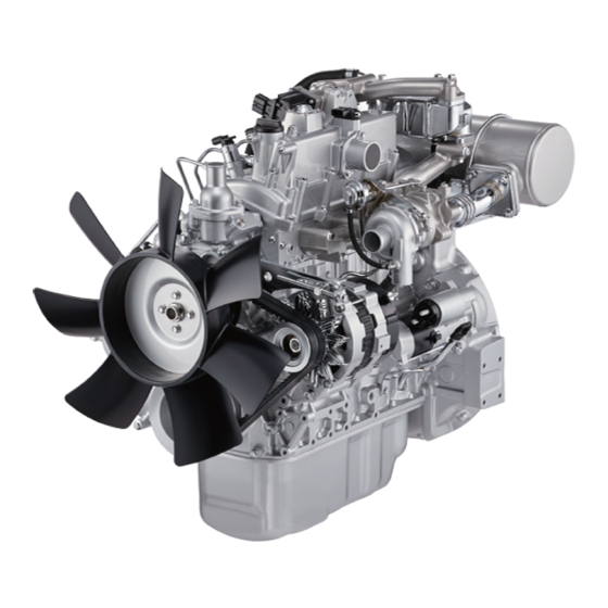
Isuzu 4LE2 Workshop Manual
Industrial diesel engine
Hide thumbs
Also See for 4LE2:
- Owner's manual (107 pages) ,
- Instruction manual (48 pages) ,
- Workshop manual (872 pages)
Table of Contents
Advertisement
Advertisement
Table of Contents

Related Manuals for Isuzu 4LE2


Summary of Contents for Isuzu 4LE2
- Page 1 INDUSTRIAL DIESEL ENGINE 4LE2 MODEL WORKSHOP MANUAL © 2003 ISUZU MOTORS LIMITED...
- Page 2 This Workshop Manual is designed to help you perform necessary maintenance, service, and repair procedures on applicable Isuzu industrial engines. Information contained in this Workshop Manual is the latest available at the time of publication. Isuzu reserves the right to make changes at any time without prior notice.
- Page 3 TABLE OF CONTENTS SECTION 1. GENERAL INFORMATION........SECTION 2.
-
Page 4: Table Of Contents
GENERAL INFORMATION SECTION 1 GENERAL INFORMATION TABLE OF CONTENTS CONTENTS PAGE GENERAL REPAIR INSTRUCTIONS ............... NOTES ON THE FORMAT OF THIS MANUAL . -
Page 5: General Repair Instructions
NOTES ON THE FORMAT OF THIS MANUAL This Workshop Manual is applicable to the 4LE2 family of industrial diesel engines. Unless otherwise specified, these engines have common parts and components as well as data and specifications. Illustrations used in this Workshop Manual are based on the 4LE2 engines. - Page 6 GENERAL INFORMATION 6. Each service operation section in this Workshop Manual begins with an exploded view of the applica- ble area. (Example) Major components Figures in parentheses “( )” show the order of disassembling or reassembling. Water Outlet Pipe (5) Packing (6) Thermostat (7) Water pump ASM (8)
- Page 7 . . . Specified Torque (Tighten) Special Tool Use Required for Recommended . . . Alignment (Marks) . . . (Isuzu Tool or Tools) Commercially Available Tool Use Required or . . . Directional Indication . . . Recommended . . .
-
Page 8: Appearance
GENERAL INFORMATION APPEARANCE 1. MODEL 4LE2 (1) Left side view Fig. 2 (2) Right side view Fig. 3... -
Page 9: Main Data And Specifications
GENERAL INFORMATION MAIN DATA AND SPECIFICATIONS 1. MODEL 4LE2 Engine model(s) 4LE2 Item Type 4-cycle, verlical in-line, water cooled, OHV Timing drive system Gear drive No. of cylinders - bore × stroke 4 – 85 × 92 Displacement L (cid) 2.179 (133) -
Page 10: Tightening Torque Specifications
GENERAL INFORMATION TIGHTENING TORQUE SPECIFICATIONS The tightening torque values given in the table below are applicable to the bolts unless otherwise specified. STANDARD BOLT N·m (kgf·m) Bolt Identification Bolt Diameter × pitch (mm) M 6 × 1.0 003.9〜007.8 {00.4〜00.8} 004.9〜009.8 {00.5〜01.0} M 8 ×... - Page 11 GENERAL INFORMATION TIGHTENING TORQUE SPECIFICATIONS The tightening torque values given in the table below are applicable to the bolts unless otherwise specified. FLANGED HEAD BOLT N·m (kgf·m) Bolt Identification Bolt Diameter × pitch (mm) M 6 × 1.0 004.6〜008.5 {00.5〜00.9} 006.6〜012.2 {00.6〜01.2} M 8 ×...
-
Page 12: Angular Nut And Bolt Tightening Method
GENERAL INFORMATION ANGULAR NUT AND BOLT TIGHTENING METHOD 1. Carefully wash the nuts and bolts to remove all oil and grease. 2. Apply a coat of molybdenum disulfide grease to the threads and setting faces of the nuts and bolts. Fig. - Page 13 GENERAL INFORMATION 5. Draw another line [C-D] on the face of each of the parts to be clamped. This line should be an exten- Line sion of the line [A-B]. Fig. 7 6. Draw another line [F-G] on the face of each of the parts to be clamped.
-
Page 14: Tightening Torque On Major Components
GENERAL INFORMATION TIGHTENING TORQUE ON MAJOR COMPONENTS 1. COOLING FAN AND WATER PUMP N·m (kgf·m/ft. lb) 19 – 28 (1.9 – 2.9 / 14 – 21) 12 – 18 (1.2 – 1.8 / 9 – 13) 12 – 18 (1.2 – 1.8 / 9 – 13) 19 –... - Page 15 GENERAL INFORMATION 2. CYLINDER HEAD AND CYLINDER HEAD COVER N·m (kgf·m/ft. lb) 8 – 12 (0.8 – 1.2 / 6 – 9) 8 – 12 (0.8 – 1.2 / 6 – 8) 2 – 4 (0.2 – 0.4 / 1.4 – 2.9) 8 –...
- Page 17 GENERAL INFORMATION 4. CYLINDER BLOCK AND OTHER COMPONENTS (2) N·m (kgf·m/ft. lb) 20 – 25 (2.0 – 2.5 / 15 – 18) 10 – 14 (1.0 – 1.4 / 7 – 10) 15 – 25 (1.5 – 2.5 / 11 – 18) 31 –...
- Page 18 GENERAL INFORMATION 5. CYLINDER BLOCK AND OTHER COMPONENTS (3) N·m (kgf·m/ft. lb) Apply Locktite No.262 (2 locations). 8 – 12 (0.8 – 1.2 / 6 – 9) 12 – 16 (1.2 – 1.6 / 9 – 12) 8 – 12 Rotate 3/4 turn after (0.8 –...
- Page 19 GENERAL INFORMATION 6. TURBOCHARGER N·m (kgf·m/ft. lb) 19 – 28 (1.9 – 2.9 / 14 – 21) Fig. 16...
-
Page 20: Gasket Location
GENERAL INFORMATION GASKET LOCATION 1. LOCATIONS WHERE GASKETS ARE USED Packin; nozzle holder Gasket; nozzle holder Packin; joint bolt Packin; headcover O-ring (※) Sealant should not be applied. Gasket Seal; valve Packin; water outlet pipe Gasket; Packin; cylinder head idle spring set screw Packin;... - Page 21 (2) When using the gasket remover “Bundo 391D” made by Three-Bond (Isuzu’s Part No. 1-8840-0542-0) to facilitate the “cleaning work”, apply the remover and leave it as is for “about 10 minutes” before starting the removal work.
- Page 22 GENERAL INFORMATION Deter- Bolt hole Dent mina tion Apply onto the bore surface Dent of the bolt hole. Specified bead width (Reference) Anaerobic : 2 ~ 3 mm Others : 2 ~ 6 mm Caution: When the application method is being designated in the repair manual, follow the designation. 3.
-
Page 23: Maintenance
GENERAL INFORMATION MAINTENANCE 1. VALVE CLEARANCE AND ADJUSTMENT Note: The cylinder head bolts were previously tightened with the “Angular Tightening Method”. Therefore, it is not necessary to retighten the cylinder head bolts before adjusting the valve clearance. Fig. 19 1. Bring the piston in either the No. 1 cylinder or the No. - Page 24 GENERAL INFORMATION 2. LUBRICATIN SYSTEM Cartridge (Spin-On) Type Cartridge Removal Remover and Installer: Filter Wrench 1. Loosen the used oil filter by turning it counterclock- wise with the filter wrench. 2. Discard the used oil filter. Installation 1. Wipe the oil filter mounting face with a clean rag. Fig.
- Page 25 GENERAL INFORMATION 4. INJECTION TIMING Note: Take care to avoid entry of dust or foreign particles into the pump interior when the timing adjustment is made. Remove the injection pipe of the No. 1 cylinder. Delivery valve Injection pump holder Remove the delivery valve holder of the injection pump of the No.
- Page 26 GENERAL INFORMATION Air bleeding from fuel (automatic air-bleeding system) For the automatic air-bleeding system When the starter switch is set to “OPERATION”, the electromagnetic pump is activated to force-feed fuel to the fuel pipe and the leak-off pipe, and air in the fuel system is automatically bled.
- Page 27 GENERAL INFORMATION 6. FUEL SYSTEM Fuel Filter Replacement Cartridge (Spin-On) Type Removal Loosen the fuel filter by turning it counterclockwise with the filter wrench or your hand. Discard the used filter. Filter Wrench Wipe the fuel filter fitting face clean with a rag. This will allow the new fuel filter to seat properly.
-
Page 28: Recommended Lubricating Oil
GENERAL INFORMATION RECOMMENDED LUBRICATING OIL TYPE OF LUBRICANTS (API) DIESEL ENGINE OIL; CC OR CD GRADE ENGINE OIL VISCOSITY CHART ENGINE OIL VISCOSITY GRADE – AMBIENT TEMPERATURE SAE 5W–20 [Single grade] SAE 20, 20W SAE 40 SAE 10W SAE 30 Ambient –25°C –20°C... - Page 29 MEMO...
- Page 30 ENGINE SECTION 2 ENGINE TABLE OF CONTENTS CONTENTS PAGE DISASSEMBLY ....................28 INSPECTION AND REPAIR .
- Page 31 ENGINE DISASSEMBLY 1. EXTERNAL PARTS (Left-hand side) (10) (11) Fig. 35 (1) Exhaust silencer (2) Exhaust pipe (3) Cooling fan and spacer (4) Fan belt (5) Fan pulley (6) Generator (7) Starter (8) Exhaust manifold and gasket (9) Cylinder head cover and air intake pipe (10) Water outlet pipe and thermostat (11) Water pump assembly...
- Page 32 ENGINE 2. EXTERNAL PARTS (Right-hand side) (15) (13) (14) (12) (18) (16) (19) (17) (20) Fig. 36 (12) Injection pipe ..4 pcs. (13) Fuel hose (14) Fuel leak off pipe (15) Fuel pipe (16) Engine stop solenoid (17) Injection pump housing cover (18) Injection pump and shim .
- Page 33 ENGINE Injection pipe Leak off pipe Fuel pipe Leak off pipe Fuel pipe Loosen the sleeve nuts on the nozzle holder side and Eye bolt on the injection pump side, and then disconnect the injection pipes. Injection pipe Nozzle holder Disconnect the leak off pipe together with gaskets.
- Page 34 ENGINE NOTE: Injection pump Mark each injection pump as to which cylinder it center position Control link was removed from. Do not reuse the shim, replace it with the same thickness that was removed. Injection pump rack pin Fig. 42 Injection pump ASM Shim * Stud...
- Page 35 ENGINE 3. INTERNAL PARTS Disassembly Steps (1) Rocker Bracket Assembly (2) Push Rods (3) Rear Hanger (4) Front Hanger (5) Cylinder Head Assembly (6) Cylinder Head Gasket (7) Tappets (8) Oil Pan (9) Oil Strainer (10) Oil Pipe (11) Crank Pulley (12) Flywheel (13) Flywheel Housing (14) Timing Gear Case (without PTO)
- Page 36 ENGINE Internal Parts (1/3) (14) (18) (17) (16) (15) Fig. 44...
- Page 37 ENGINE Internal Parts (2/3) (20) (13) Do not pull out this bolt. ※ (12) (21) (10) Rear (19) (11) Fig. 45...
- Page 38 ENGINE Internal Parts (3/3) When provided with PTO (14-2) (14-1) (15) Fig. 46...
- Page 39 ENGINE Rocker bracket Install of nuts (6) Push rod Remove the rocker bracket assembly. Install of (M6 × 1 ..5 bolts and 6 nuts) bolts (5) Pull out the push rods (8 pcs.). ※ Marks : Thread hole (M8 x 1.25) for replacer of rocker bracket assembly ※...
- Page 40 ENGINE Cylinder Head Assembly Glow plug (2) Connector (1) Seal; valve Split collar (4) Guide; valve Spring seat (5) Valve spring (6) Studs are applied with sealing agent. Do not pull them out. (5 locations) Nozzle holder (3) Valve (7) Hot plug Seat;...
- Page 41 ENGINE Timing Gear Bearing Wear ring Cam shaft (8) Bearing Snap ring (7) Cam gear (6) Fly weight ASM (5) Shaft; idle gear (3) Lock nut Idle gear (2) Sleeve (4) Thrust collar Crankshaft Crank gear Crank pulley (1) Washer Fig.
- Page 42 ENGINE Timing gear Remove the idle gear and the idle gear shaft. Pull out the sleeve from the tip end of the cam shaft. Remove the lock nut of the cam shaft gear, and then remove the flyweight assembly and the cam gear. Camshaft Remove the snap ring which holds down the front Crankshaft...
- Page 43 ENGINE Piston and Connecting Rod Piston ring (4) Snap Pipe (5) Piston Piston pin (6) Bush (The drawing-out of the bush must be limited to only when replaced. Con’rod bolt (The drawing-out ot the con’rod bolt must be limited to only when replaced.) Connecting rod (7) Cap (6) Cap nut (1)
- Page 44 ENGINE Piston ring Remove the piston ring with a ring pliers. Pliers: piston ring 1-85221-029-0 Fig. 55 Piston pin Brass bar Remove the snap rings with a commercially avail- able tool. With a brass bar attached to the piston pin, push it out by hammering it lightly.
- Page 45 ENGINE INSPECTION AND REPAIR Make the necessary adjustments, repairs, and part replacements if excessive wear or damage is dis- covered during inspection. 1. CYLINDER BLOCK Cylinder block Check the cylinder block for wear, damage or any other defects. Use the hydraulic gauge to check the water jacket water pressure.
- Page 46 Engine Bore Diameter Grade 85.000 – 85.010 (3.3464 – 3.3468) 85.011 – 85.020 4LE2 (3.3468 – 3.3472) 85.021 – 85.030 (3.3472 – 3.3476) Cylinder Body Upper Face Warpage Use a straight edge 1 and a feeler gauge 2 to measure the four sides and the two diagonals of the cylinder body upper face.
- Page 47 0.075 (0.0029) 0.15 (0.0059) 0.3 (0.0118) Fig. 65 Cylinder Head Height H (Reference) mm (in) Engine Standard 63.90 – 64.10 4LE2 (2.515 – 2.523) Note: If the cylinder head lower face is reground, valve depression must be checked. Fig. 66...
- Page 48 ENGINE 3. VALVE, VALVE SEAT INSERT AND VALVE SEAL Inspection of valve seat Cylinder head A – Contact width Valve B – Valve depression mm (in) Standard Limit Contact width 2.0 (0.0787) 2.5 (0.0984) 0.7 (0.0276) 1.2 (0.0427) Valve depression 0.9 (0.0354) 1.5 (0.0591) 45°...
- Page 49 ENGINE Valve Seat Insert Replacement Valve Seat Insert Removal Arc weld the entire inside circumference 1 of the valve seat insert 2. Allow the valve seat insert to cool for a few minutes. This will invite contraction and make removal of the valve seat insert easier.
- Page 50 ENGINE Apply abrasive compound to the valve seat insert surface. Insert the valve into the valve guide. Apply light pressure to the valve while turning it to fit the valve seat insert. Check that the valve contact width is correct. Check that the valve seat insert surface is in contact with the entire circumference of the valve.
- Page 51 ENGINE 5. TAPPET (Cam Follower or Valve Lifter) AND PUSH ROD TAPPET Inspect the tappets for excessive wear, damage and any abnormalities. Use a micrometer to measure the tappet diameter. mm (in) Standard 20.967 – 20.980 Tappet Diameter (0.82547 – 0.82598) Fig.
- Page 52 ENGINE 6. CAM SHAFT Inspection of cam shaft Check the journal and the cam for evidence of wear, Camshaft damage or any other defect. Note: With the front and rear parts of camshaft pressed in with ball bearings, and with the cylinder block pressed in with roller bearings as the center bearing, check to see if the camshaft rotates smoothly with no play at each bearing.
- Page 53 ENGINE 7. ROCKER ARM SHAFT AND ROCKER ARM Inspect all disassembled parts for wear, damage and any abnormalities. Fig. 85 Rocker Arm Shaft Outside Diameter Use a micrometer to measure the rocker arm outside diameter. If the measured value is less than the specified limit, the shaft must be replaced.
- Page 54 The piston for service part doesn’t have the grade. mm (in) Model Outside diameter of piston Grade 84.945 – 84.960 4LE2 (3.3443 – 3.3449) Fig. 90 Wear of piston pin (outside diameter) mm (in) Nominal Limit Remarks 25.0...
- Page 55 Clearance between piston pin and piston pin hole mm (in) Standard 0.007 – 0.017 4LE2 (0.00027 – 0.00067) Piston ring gap With the ring inserted into the cylinder bore, push it in with the piston head so that it becomes a right angle to the cylinder, and then measure the gap of the piston ring.
- Page 56 ENGINE 9. CONNECTING ROD AND CONNECTING ROD BEARING Torsion and parallelism of connecting rod If worn beyond the limit-repair or replace. mm (in) Per 100 mm (3.94) Standard Limit 0.05 Torsion (0.002) (0.0079) 0.05 0.15 Parallelism (0.002) (0.0059) Fig. 94 Clearance between small end pin hole of connecting rod and piston pin, inside diameter of bushing mm (in)
- Page 57 ENGINE 10.CRANKSHAFT AND CRANKSHAFT BEARING Outside diameters of journal and pin If worn beyond the limits-replace Crank journal mm (in) Standard Limit 4LE2 60.0 (2.3622) 59.86 (2.3567) Crank pin mm (in) Standard Limit Fig. 98 4LE2 49.0 (1.9291) 48.87 (1.9240)
- Page 58 ENGINE Oil seal Timing gear case When the lip of an oil seal is found defective, replace it with a new one. Installation Use the crankshaft front oil seal installer to install the Front oil seal crankshaft front oil seal. Fig.
- Page 59 ENGINE REASSEMBLY 1. CYLINDER HEAD ASSEMBLY Glow plug (7) Connector (8) Seal; valve (1) Split collar (5) Guide; valve Spring seat (4) Valve spring (3) Apply Locktite No.262 to this portion. (5 locations) Nozzle holder (6) Valve (2) Hot plug Seat;...
- Page 60 ENGINE Intake and Exhaust Valve Springs Install the valve springs with their painted end (the close pitched end) facing down. Painted potion Fig. 110 Spring Seat Split Collar Spring compressor Split collar Use a spring compressor to push the valve spring into position.
- Page 61 Install the connecting rod to the piston with setting the marks as illustrated. Install the piston pin into the piston and the connect- ing rod bushing. Fig. 115 Front mark (Hot plug side) Engine front direction Isuzu mark Cylinder number stamped side Fig. 116...
- Page 62 ENGINE Piston Pin Snap Ring Use a pair of snap ring pliers to install the piston pin snap ring. Check that the piston moves smoothly on the piston pin. Fig. 117 Piston Ring Use a piston ring installer to install the three piston rings.
- Page 63 ENGINE 3. INTERNAL PARTS Reassembly Steps (1) Crankshaft (2) Piston Assembly (3) Rear Seal Retainer (4) Camshaft (5) Cam Gear (6) Idler gear and Shaft (7) Oil Pump Assembly (8) Timing Gear Case (Without PTO) (9) Flywheel Housing (10) Flywheel (11) Crank Pulley (12) Oil Pipe (13) Oil Strainer...
- Page 64 ENGINE Internal Parts (1/3) (13) ※ (10) (12) Rear (11) (14) Fig. 119...
- Page 65 ENGINE Internal Parts (2/3) (19) (20) (18) (17) (15) (20) (16) Fig. 120...
- Page 66 ENGINE Internal Parts (3/3) (8-1) (8-2) Fig. 121...
- Page 67 ENGINE Crankshaft bearing With oil hole Fit correctry and groove Note that there is an oil hole and an oil groove in the (Upper) upper bearing (on the block side), but not in the lower bearing (on the bearing cap side). Fit the bearing tang firmly into the slot machined on the cylinder body bearing arches.
- Page 68 ENGINE Position the rings as shown making sure the ring gaps are away from the thrust side. Fig. 125 Piston and Connecting Rod Special tool Lubricate the piston, the piston rings, and the connect- ing rod bearings with engine oil. Position the piston front mark towards the front of the Front mark engine.
- Page 69 ENGINE Camshaft assembly Apply engine oil to the inside of the bearing of the cylinder block, and then install the camshaft assembly. Note: When installing the assembly, care should be taken not to damage the bearing. After installation of the snap ring to the outside of the front bearing, check to see if the camshaft rotates smoothly.
- Page 70 ENGINE Oil pump assembly When PTO is not provided, install the oil pump Cylinder block assembly to the cylinder block. PTO not provided N·m (kgf·m/ft. lb) Tightening torque 19 - 28 (1.9 – 2.9 / 14 – 21) Fig. 133 When PTO is provided, install the oil pump to the front plate.
- Page 71 ENGINE Timing gear case (with governor) Governor cover When not provided with PTO, install the timing gear case to the cylinder block. When provided with PTO, install it to the front plate. Timing gear case Put the link plate of the governor incorporated in the gear case through the connecting hole of the injection pump in advance.
- Page 72 ENGINE Crank pulley Lubricate the lip of the front, seal with oil Install the crank pulley, lock the crankshaft and tighten Crankshaft the front bolt. N·m (kgf·m/ft. lb) Crank pulley Tightening torque 167 - 186 (17 – 19 /123 – 137) Washer Front oil seal Fig.
- Page 73 ENGINE Cylinder head assembly Lubricate the bolts with oil. Tighten the bolts in the sequence shown in the illustra- tion to the specified torque. N·m (kgf·m/ft. lb) Bolt size Tightening torque M12 × 1.5 83 – 93 60°〜90° (8 each) (8.5 - 9.5 / 61 –...
- Page 74 ENGINE Adjustment of valve clearance Refer to Section “General Information – Maintenance” (on page 20). Front hanger and rear hanger Rear hanger Tighten them to the specified torque shown below. N·m (kgf·m/ft. lb) Tightening torque 19 - 28 (1.9 – 2.9 / 14 – 21) Front hanger Fig.
- Page 75 ENGINE 4. EXTERNAL PARTS (Right-hand Side) Fig. 148 (1) Dipstick (2) Oil Filter (3) Injection Pump (4) Injection Pump Housing Cover (5) Fuel Pipe (6) Leak Off Pipe (7) Fuel Hose (8) Injection Pipe...
- Page 76 ENGINE 5. EXTERNAL PARTS (Left-hand Side) (18) (11) (10) (19) (12) (17) (15) (13) (16) (14) Fig. 149 (9) Water Pump (10) Thermostat and Water Outlet Pipe (11) Cylinder Head Cover (12) Exhaust Manifold (13) Starter (14) Generator (15) Fan Pulley (16) Fan Belt (17) Cooling Fan (18) Exhaust Pipe...
- Page 77 ENGINE Dipstick Dipstick Oil filter (cartridge) Cartridge Insert the dipstick. Install the cartridge with a filter wrench (commer- cially available). (1) Apply engine oil thinly to the gasket of the cartridge. (2) Screw in the cartridge until the gasket comes into contact with the seal, and then tighten it by giving it about 3/4 turns.
- Page 78 ENGINE Injection pump housing cover After applying sealant (TB1207B) to the housing cover, Housing cover install it to the cylinder block by the side of the injection pump. N·m (kgf·m/ft. lb) Tightening torque 8 - 12 (0.8 – 1.2 / 6 – 9) Note: The areas of the housing cover to which liquid gasket is applied are about 4 mm in width from the cover edge...
- Page 79 ENGINE Fuel pipe Fuel pipe Leak off pipe Leak off pipe Fuel hose Install the fuel pipe to the injection pump and then tighten it to the specified torque. Install the leak off pipe to the nozzle holder and then Nozzle holder tighten it to the specified torque.
- Page 80 ENGINE Adjustment of valve clearance (Refer to Section “GENERAL INFORMATION – MAINTE- NANCE.”) Cylinder head cover Cylinder cover Install the gasket to the cylinder head cover. Notes: Gasket Much care should be taken for the gasket not to get dislocated or twisted when installing the head cover.
- Page 81 ENGINE Generator Water pump Tighten the adjust plate together with the water pump, and then install them temporarily. Adjusting plate Install the bottom of the alternator to the timing gear case, and then tighten it temporarily with bolts and nuts. Install the fixing bolts onto the top of the alternator through the adjusting plate.
- Page 82 LUBRICATING SYSTEM SECTION 3 LUBRICATING SYSTEM TABLE OF CONTENTS CONTENTS PAGE LUBRICATING OIL CIRCULATION SYSTEM DIAGRAM ........80 OIL PUMP.
- Page 83 LUBRICATING SYSTEM LUBRICATING OIL CIRCULATION DIAGRAM Valve opening pressure 98 kPa (1kgf/cm Oil filter Oil gallery Main bearing Idle gear bush Cylinder head Valve opening Rocker arm pressure Crankshaft Timing gear bracket 440 kPa (4.5kgf/cm Connecting rod Governor Rocker shaft Rocker arm Oil pump Injection pump...
- Page 84 LUBRICATING SYSTEM OIL PUMP With PTO Body; Oil pump Front plate (Body; integral structure) Pin (common) Without PTO Rotor; outer Roter; inner O-ring (common) Relief valve Pump gear Spring Plug Common Oil pump (common) Fig. 171 Inspection and replacement When there is wear, damages or any other defects found, repair or replace the rotor.
- Page 85 MEMO...
- Page 86 COOLING SYSTEM SECTION 4 COOLING SYSTEM TABLE OF CONTENTS CONTENTS PAGE COOLING WATER CIRCULATION SYSTEM DIAGRAM ........84 WATER PUMP .
- Page 87 COOLING SYSTEM COOLING WATER CIRCULATION SYSTEM DIAGRAM Bottom bypass type thermostat Cyliner head Cylinder block bypass circuit) Water pump Radiator Fig. 172...
- Page 88 COOLING SYSTEM WATER PUMP DISASSEMBLY Seal unit Impeller Bearing unit Fan center Cover Body Setscrew Fig. 173 Fan center Cover Cover Loosen the set screw. Remove the cover. Note: The cover is applied with sealant (TB1207B). When re- moving the cover, much care should be taken not to Setscrew deform it by applying an excessive force to it.
- Page 89 COOLING SYSTEM REASSEMBLY Bearing unit With a hole in the bearing unit set in line with one in the Align holes body, lock the bearing unit with a setscrew. Body Bearing unit N·m (kgf·m/ft. lb) Set screw tightening torque 8 - 12 (0.8 – 1.2 / 6 – 9) Fan center Setscrew Fig.
- Page 90 COOLING SYSTEM THERMOSTAT Inspection and replacement Replace the thermostat when there is wear, damages or any other defects found. Opening temp. 80.5 – 83.5°C (177 – 182°F) Thermometer 8mm or more at 95°C Valve lift mm (in.) (0.31 inch or more at 203°F) Agitating rod Thermostat Wooden piece...
- Page 91 MEMO...
- Page 92 FUEL SYSTEM SECTION 5 FUEL SYSTEM TABLE OF CONTENTS CONTENTS PAGE FUEL CIRCULATION SYSTEM DIAGRAM ..........90 GOVERNOR .
- Page 93 FUEL SYSTEM FUEL CIRCULATION SYSTEM DIAGRAM Fuel tank Nozzle holder Injection pump Nozzle Fuel filter Fig. 180...
- Page 94 FUEL SYSTEM GOVERNOR The adjustments of the governor-related parts require the engine performance test. Before disassembling the governor, measure the dimensions “A” and “B” given in the structural drawing to ensure the same dimensions in reassembly. Do not disassemble the governor when the performance test cannot be conducted after reassembly. 1.
- Page 95 FUEL SYSTEM 2. STRUCTURAL DRAWING OF GOVERNOR (2) Start spring Control link Set spring Snap pin Guide lever Floating lever Link plate Cap nut Guide piece Shifter Setscrew Shaft (floating) Main Fuel cut lever Fuel cut shaft spring Return spring Shifter shaft Tensioner O-ring...
- Page 96 FUEL SYSTEM 3. REASSEMBLY OF CONTROL LEVER RELATED PARTS (1) Put the lever (main spring) through the hole of the timing gear case lever. Note: Before hammering in the bushes, put both shafts of the lever through the holes of the timing gear case lever respectively.
- Page 97 FUEL SYSTEM (6) Assemble the control lever. Assemble the O-ring to the groove of the bushes (control lever) first, and then assemble the washers and the control lever before tightening up the control lever with a nut. N·m (kgf·m/ft. lb) Control lever tightening torque 12 - 18 (1.2 –...
- Page 98 FUEL SYSTEM 4. Reassembly of shifter (1) Assemble the shifter to the guide lever, put the shaft through it, and then assemble the snap ring. (2) After assembly, confirm that the shaft moves smoothly. (3) Also, confirm that the shifter shakes smoothly. Guide lever Shifter Snap ring...
- Page 99 FUEL SYSTEM 5. Reassembly of governor cover Assemble the related parts such as the fuel cut lever and the idle spring to the governor cover. [Stop] [Operate] Governor cover Return spring Governor (Bent-up part) Thrust washer Idle spring O-ring Shaft Spring washer (Notched groove) Fuel cut lever...
- Page 100 FUEL SYSTEM 6. Reassembly of full-load stopper Install the full-load stopper to the timing gear case, and then tighten it with a nut temporarily. Timing gear case Full load stopper Nut; setscrew Fig. 188...
- Page 101 FUEL SYSTEM 7. Reassembly of governor lever related components Assemble each lever and spring to the timing gear case. Main spring lever Lever shaft Tensioner lever Link plate Main spring Eye; start spring Set spring Guide piece Start spring Guide lever Snap pin Plug Floating lever...
- Page 102 FUEL SYSTEM NOZZLE HOLDER ASSEMBLY DISASSEMBLY Push rod Bolt Spacer Gasket Gasket Nozzle Nozzle holder Retainer nut Adjusting shim Spring Fig. 190 NOZZLE ASSEMBLY Inspection and replacement Place the removed nozzle in the clean light oil, disas- semble it into the nozzle body and the needle valve and clean them thoroughly.
- Page 103 MEMO...
- Page 104 TROUBLESHOOTING SECTION 6 TROUBLESHOOTING Engine does not start Starter does not run Engine starts but Starter runs but does does not run not start continuously. Check battery Fuel system Fuel injected Engine Air mixed in fuel pump Battery in discharging Check (Charge) compression...
- Page 105 TROUBLESHOOTING Unstable engine rotation Unstable rotation at Engine does not Unstable engine Idling speed Unstable rotation at medium speed change from high to idling too high high speed (Hunting) low rotation Defective idling Defective control Check fuel for air Check accelerator Governor spring adjustment lever adjustment...
- Page 106 TROUBLESHOOTING Insufficient output Overheat Fuel system Cooling system Handling Mechanical system Check fuel for air Check cooling Check fan belt Check if oil used mixing water level for slip is inferior quality, Check engine or engine oil is control too much Insufficient Slipping Air mixed...
- Page 107 TROUBLESHOOTING Abnormal exhaust gas White smoke too much Black smoke too much Air cleaner clogged Check nozzle Check if fuel used is of Check fuel for water inferior quality mixing Replace air Defective cleaner element (Repair or replace) Change fuel Water mixed (Change fuel) Check air hose for crash...
- Page 108 TROUBLESHOOTING Oil pressure too low Oil consumption too much Oil consumption too much Check oil level Check for oil leakage Check for oil leakage Low (Replenish) Leaking (Retighten, Leaking (Retighten, replace packing seal) replace packing seal) Check cooling water temperature Check nozzle Check oil quality High...
- Page 109 MEMO...
- Page 110 SPECIAL TOOLS SECTION 7 SPECIAL TOOLS The alphanumeric codes in parentheses “( )” are part numbers assigned by special tool manufacturers. Illustration Part Number Part Name Page 5-8840-2675-0 Compression gauge 5-8840-9029-0 Compression gauge adapter 5-8840-9016-0 Nozzle tester (J-28829) 5-8840-9015-0 Oil filter wrench —...
- Page 111 MEMO...
-
Page 112: Length
CONVERSION TABLE SECTION 8 CONVERSION TABLE TABLE OF CONTENTS ITEM PAGE LENGTH ............... 109 AREA . - Page 113 CONVERSION TABLE LENGTH FEET TO METERS ––– –––0 0.305 0.610 0.914 1.219 1.524 1.829 2.134 2.438 2.743 ––– 3.048 3.353 3.658 3.962 4.267 4.572 4.877 5.182 5.486 5.791 6.096 6.401 6.706 7.010 7.315 7.620 7.925 8.230 8.534 8.839 9.144 9.449 9.754 10.058 10.363...
-
Page 114: Area
CONVERSION TABLE AREA SQUARE INCHES TO SQUARE CENTIMETERS ––– –––00 6.452 12.903 19.355 25.806 32.258 38.710 45.161 51.613 58.064 ––– 64.516 70.968 77.419 83.871 90.322 96.774 103.226 109.677 116.129 122.580 129.032 135.484 141.935 148.387 154.838 161.290 167.742 174.193 180.645 187.096 193.548 200.000 206.451... - Page 115 CONVERSION TABLE VOLUME GALLONS (U.S.) TO LITERS U.S. gal. U.S.gal. liters liters liters liters liters liters liters liters liters liters ––– –––00 3.7854 7.5709 11.3563 15.1417 18.9271 22.7126 26.4980 30.2834 34.0688 ––– 37.8543 41.6397 45.4251 49.2106 52.9960 56.7814 60.5668 64.3523 68.1377 71.9231 75.7085...
-
Page 116: Mass
CONVERSION TABLE MASS POUNDS TO KILOGRAMS lbs. lbs. ––– –––0 0.454 0.907 1.361 1.814 2.268 2.722 3.175 3.629 4.082 ––– 4.536 4.989 5.443 5.897 6.350 6.804 7.257 7.711 8.165 8.618 9.072 9.525 9.979 10.433 10.886 11.340 11.793 12.247 12.701 13.154 13.608 14.061 14.515... -
Page 117: Pressure
CONVERSION TABLE PRESSURE POUNDS PER SQUARE INCHES TO KILOGRAMS PER SQUARE CENTIMETERS lb/in lb/in (psi) kg/cm kg/cm kg/cm kg/cm kg/cm kg/cm kg/cm kg/cm kg/cm kg/cm (psi) ––– –––0 0.0703 0.1406 0.2109 0.2812 0.3515 0.4218 0.4921 0.5625 0.6328 ––– 0.7031 0.7734 0.8437 0.9140 0.9843... -
Page 118: Torque
CONVERSION TABLE TORQUE FOOT POUNDS TO KILOGRAMMETERS ft. lbs. ft lbs. kg-m kg-m kg-m kg-m kg-m kg-m kg-m kg-m kg-m kg-m ––– –––0 0.138 0.277 0.415 0.553 0.691 0.830 0.968 1.106 1.244 ––– 1.383 1.521 1.659 1.797 1.936 2.074 2.212 2.350 2.489 2.627... -
Page 119: Temperature
CONVERSION TABLE TEMPERATURE FAHRENHEIT TO CENTIGRADE °F °C °F °C °F °C °F °C °F °C °F °C °F °C °F °C -51.1 -18.9 13.3 45.6 77.8 110.0 142.2 174.4 -50.0 -17.8 14.4 46.7 78.9 111.1 143.3 175.6 -48.9 -16.7 15.6 47.8 80.0... - Page 120 Copyright reserved for this manual may not be reproduced or copied, in whole or in part, without the written consent of ISUZU MOTORS LIMITED. WORKSHOP MANUAL (INDUSTRIAL) 4LE2 (IDE-2330) Issued by ISUZU MOTORS LIMITED Powertrain Service & Parts Powertrain Operations...
- Page 121 IDE-2330 PRINTED IN JAPAN...
Need help?
Do you have a question about the 4LE2 and is the answer not in the manual?
Questions and answers
I just bought a used 25 KVA genset. How do I find the year of this engine and generator? DCA 25ESIB ; DF 270i. Engine AA 4LE2, dao1,ajo1
@Larry Jensen
The year of an Isuzu 4LE2 engine can be determined by a letter code for the model year marked on the top of the letters on the engine. For example, "Y" represents 2000, "1" represents 2001, "2" represents 2002, and so on.
There is no specific method mentioned to determine the year of the DCA-25ESI generator.
This answer is automatically generated
what tier IS MY 4LED and is it a a-4ja1 or 4bg1 or 4bd1 or many other codes. What year is it and these codes were on the valve cover.AA4LI-DA201, AJA1. I no photo of engine so I sent a dog photo.