Table of Contents

Advertisement

1. STARTER INOPERATIVE

Checkpoint
Battery
Fusible link
Starter switch
Starter motor

2. STARTER MOTOR OPERATES BUT ENGINE DOES NOT TURN OVER

Battery
Starter
Engine

1. HARD STARTING

Possible cause
Loose battery cable terminal poor
connections due to rusting
Battery discharged or weak
Fan belt loose or broken
Fusible link shorted
Defective starter switch or starter relay
Defective magnetic switch or starter relay
Defective starter motor
Loose battery cable terminal
Poor connections due to rusting
Battery discharged or weak
Fan belt loose or broken
Defective pinion gear
Defective magnetic switch
Brush wear, Weak brush spring
Piston, crank bearing seizure, or other
damage
SERVICE INFORMATION 00 – 3
Correction
Clean and/or retighten the battery
cable terminal
Recharge or replace the battery
Adjust or replace the fan belt
Replace the fusible link
Replace the starter switch or the
Starter relay
Repair or replace the magnetic switch
Repair or replace the starter motor
Clean and/or retighten the battery
cable terminal
Recharge or replace the battery
Adjust or replace the fan belt
Replace the pinion gear
Repair or replace the magnetic switch
Replace the brush and/or the brush
spring
Repair or replace the related parts

Advertisement

Table of Contents
loading
Need help?

Need help?

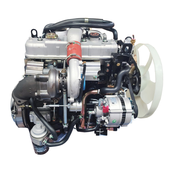
Do you have a question about the 4JB1 and is the answer not in the manual?

Questions and answers

Summary of Contents for Isuzu 4JB1

  • Page 1 SERVICE INFORMATION 00 – 3 1. HARD STARTING 1. STARTER INOPERATIVE Checkpoint Possible cause Correction Battery Loose battery cable terminal poor Clean and/or retighten the battery connections due to rusting cable terminal Battery discharged or weak Recharge or replace the battery Fan belt loose or broken Adjust or replace the fan belt Fusible link...
  • Page 2 00 – 4 SERVICE INFORMATION 3. ENGINE TURNS OVER BUT DOES NOT START Checkpoint Possible cause Correction Engine stop Defective fuel cut solenoid valve Replace the fuel cut solenoid valve mechanism FUEL IS NOT BEING DELIVERED TO THE INJECTION PUMP Fuel Fuel tank is empty Fill the fuel tank...
  • Page 3 SERVICE INFORMATION 00 – 5 4. QUICK-ON START SYSTEM PREPARATION 1 Disconnect the thermoswitch connector. 2. Determine whether or not the glow plugs are receiving power. a) Make sure that the starter switch is “OFF”. b) Connect a voltmeter between one of the glow plugs and the cylinder wall. c) Move the starter switch to the “ON”...
  • Page 4 00 – 6 SERVICE INFORMATION GLOW PLUGS ARE NOT RECEIVING POWER (Cont’d) Checkpoint Possible cause Correction Glow plug indicator Defective glow plug relay Replace the glow plug relay light turns on for 3.5 The glow plug relay does not turn on after the seconds starter switch is moved from the “OFF”...
  • Page 5 SERVICE INFORMATION 00 – 7 Checkpoint Possible cause Correction Injection pump Injection timing improperly adjusted Adjust the injection timing (Cont’d) Insufficient injection volume Adjust the injection volume Defective idle spring Replace the idle spring Defective governor lever operation Repair or replace the governor lever Regulator valve improperly adjustment Adjust or replace the regulator valve Broken plunger spring...
  • Page 6 00 – 8 SERVICE INFORMATION Checkpoint Possible cause Correction Injection pump Defective regulating valve Repair or replace the regulating valve Defective delivery valve Replace the delivery valve Defective timer Repair or replace the timer Worn cam disc Replace the cam disc Improper control lever operation Adjust or replace the control lever Defective injection timing...
  • Page 7 SERVICE INFORMATION 00 – 9 4. EXCESSIVE FUEL CONSUMPTION Checkpoint Possible cause Correction Fuel system Fuel leakage Repair or replace the fuel system related parts Air cleaner Clogged air cleaner element Clean or replace the air cleaner element Idling speed Poorly adjusted idling speed Adjust the idling speed Injection nozzle...
  • Page 8 00 – 10 SERVICE INFORMATION 6. OVERHEATING Checkpoint Possible cause Correction Cooling water Insufficient cooling water Replenish the cooling water Fan clutch Oil leakage from the fan clutch Replace the fan clutch Fan belt Fan belt loose or cracked causing slippage Replace the fan belt Radiator Defective radiator cap or clogged radiator...
  • Page 9 SERVICE INFORMATION 00 – 11 8. DARK EXHAUST SMOKE Checkpoint Possible cause Correction Air cleaner Clogged air cleaner element Clean or replace the air cleaner element Injection nozzle Injection nozzle injection starting pressure Adjust or replace the injection nozzle too low Improper spray condition Fuel injection timing Fuel injection timing improperly adjusted...
  • Page 10 00 – 12 SERVICE INFORMATION 10. ABNORMAL ENGINE NOISE 1. ENGINE KNOCKING Check to see that the engine has been thoroughly warmed up before beginning the troubleshooting procedure. Checkpoint Possible cause Correction Fuel Fuel unsuitable Replace the fuel Fuel injection timing Fuel injection timing improperly adjusted Adjust the fuel injection timing Injection nozzle...
  • Page 11 SERVICE INFORMATION 00 – 13 4. SLAPPING NOISE Checkpoint Possible cause Correction Valve clearance Valve clearance improperly adjusted Adjust the valve clearance Rocker arm Damaged rocker arm Replace the rocker arm Flywheel Loose flywheel bolts Retighten the flywheel bolts Crankshaft and thrust Worn or damaged crankshaft and/or thrust Replace the crankshaft and/or the bearings...
  • Page 12 00 – 14 SERVICE INFORMATION 11. ENGINE COOLING TROUBLE Checkpoint Possible cause Correction Engine overheating Low coolant level Replenish Thermo unit faulty Replace Faulty thermostat Replace Faulty coolant unit Repair or replace Clogged radiator Clean or replace Faulty radiator cap Replace Low engine oil level or use of improper Replenish or change oil...
  • Page 13 SERVICE INFORMATION 00 – 15 12. ENGINE ELECTRICAL PART TROUBLE STARTER DOES NOT RUN CHECK BATTERY CHARGING FAILURE OR LIFE BATTERY IS NORMAL CHECK BATTERY CHECK TERMINAL CONNECTION CONNECTION FAILURE TERMINAL CONNECTION IS NORMAL CHECK STARTER OR STARTER SWITCH CLEAN BATTERY TERMINALS, AND RECONNECT FAILURE REPAIR OR REPLACE TURN ON HEAD LAMP AND STARTER SWITCH...
  • Page 14 00 – 16 SERVICE INFORMATION FAULTY MESHING OF PINION AND RING GEAR CHECK IF BATTERY VOLTAGE IS PRESENT AT MAGNETIC SWITCH TERMINAL “S” WHEN STARTER SWITCH IS TURNED TO “START (ST)” UNDER THIS CONDITION, CHECK IF VOLTAGE OF CONNECTOR 3BW ON MAGNETIC SWITCH OF RESTART RELAY IS NORMAL EXTREME WEAR OF STARTER SLIDING...
  • Page 15 SERVICE INFORMATION 00 – 17 MAGNETIC SWITCH DOES NOT OPERATE THOUGH STARTER SWITCH IS TURNED TO “START (ST)” CHECK IF VOLTAGE IS PRESENT AT MAGNETIC SWITCH TERMINAL “S” WHEN STARTER SWITCH IS TURNED TO “START (ST)” CHECK GROUND CABLE CHECK IF INDICATOR LAMP ON METER COMES ON NORMALLY REPAIR CHECK CONTINUITY...
  • Page 16 00 – 18 SERVICE INFORMATION PINION MESHES WITH RING GEAR BUT ENGINE DOES NOT RUN CHECK GROUND CABLE REPAIR OR REPLACE GROUND CABLE FAULTY CONNECTION BURNED-OUT DISCONNECTION DISCONNECTION SLIP OF OF BRUSH AND MAGNETIC OR DAMAGE OF OR DAMAGED OF PINION COMMUTATOR STARTER SWITCH...
  • Page 17 SERVICE INFORMATION 00 – 19 STARTER DOES NOT STOP THOUGH STARTER SWITCH IS RETURNED TO “ON” FROM “START” DISCONNECTED STARTER SWITCH WIRING CONNECTOR, AND CHECK STARTER SWITCH OPERATION. BATTERY IGNITION BATTERY ACCESSORIES IGNITION STARTER POSITION LOCK START THERE MUST BE NO CONTINUITY EXCEPT ABOVE LINES. MAGNETIC SWITCH CONTACTS ARE REPLACE STARTER SWITCH FUSED AND NOT MOVED, OR A...
  • Page 18 00 – 20 SERVICE INFORMATION 13. TURBOCHARGER 1) ENGINE HAS LESS THAN NORMAL POWER Checkpoint Trouble Cause Countermeasure Air cleaner Restricted Clean or replace Intake pipe and hose Restricted Clean or replace Compressor/Intake manifold Loose (Leaking) Repair Exhaust manifold/turbine inlet Loose (Leaking) Repair Exhaust piping and silencers...
  • Page 19 SERVICE INFORMATION 00 – 21 Checkpoint Trouble Cause Countermeasure Continued from the previous page Compressor wheel Impact damage Replace Turbine wheel Impact damage Replace Carbon build-up Replace Rotating assembly Dragging or seized Replace...
  • Page 20 00 – 22 SERVICE INFORMATION 2) BLUE OR BLACK SMOKE Checkpoint Trouble Cause Countermeasure Air cleaner or intercooler Restricted Clean, repair, or replace Turbocharger oil seal Leakage Replace Turbocharger oil drain pipe Restricted Repair or replace Air breather Restricted Clean Boost compensator Defective Repair or replace...
  • Page 21 SERVICE INFORMATION 00 – 23 Checkpoint Trouble Cause Countermeasure Continued from the previous page Center housing oil drain passage Restricted Clean or replace...
  • Page 22 00 – 24 SERVICE INFORMATION 3) EXCESSIVE OIL CONSUMPTION Checkpoint Trouble Cause Countermeasure Air breather Restricted Clean Boost compensator Defective Repair or replace (Injection pump) Turbocharger oil seal Leakage Replace Turbocharger oil drain pipe Restricted Clean or replace Turbine wheel Impact damage Replace Compressor wheel...
  • Page 23 SERVICE INFORMATION 00 – 25 Checkpoint Trouble Cause Countermeasure Continued from the previous page Center housing oil drain passage Restricted Clean or replace...
  • Page 24 00 – 26 SERVICE INFORMATION 4) EXCESSIVE TURBOCHARGER NOISE Checkpoint Trouble Cause Countermeasure Intake and exhaust Restricted Repair system joints Intake and exhaust system Damaged Replace gaskets Turbocharger rotating parts Rough rotation Replace Compressor wheel Rubbing against housing Repair or replace Damaged Replace Turbine wheel...
  • Page 25 SERVICE INFORMATION 00 – 27 Checkpoint Trouble Cause Countermeasure Continued from the previous page Oil level Too low Correct Contaminated Replace oil Turbocharger oil feed pipe Restricted Repair or replace Turbine housing Carbon deposits Clean Compressor housing Dirty Clean Turbine shaft bearings Worn Replace...
  • Page 26 00 – 28 SERVICE INFORMATION 5) EXCESSIVE ROTATING PART WEAR Checkpoint Trouble Cause Countermeasure Engine oil Contaminated Change Wrong grade or type Change Turbocharger oil feed pipe Restricted Clean or replace Turbocharger oil seal Defective Replace Center housing oil Restricted Clean or replace drain passage Turbine shaft...
  • Page 27 SERVICE INFORMATION 00 – 29 LUBRICATION CHART 4JB1, 4JB1TC, 4JG2, Oil Filter & Oil Cooler kPa (Kg/cm /psi) Oil filter relief valve opening pressure 559 - 0618 (5.7 - 6.3/81 - 90) " Oil cooler safety valve opening pressure 314 - 373 (3.2 - 3.8/46 - 54) Oil filter safety valve opening pressure 78 - 118 (0.8 - 1.2/11 - 19)
  • Page 28 00 – 30 SERVICE INFORMATION MAIN DATA AND SPECIFICATIONS MAIN DATA AND SPECIFICATIONS Engine Model 4JB1 / 4JB1T / 4JB1TC 4JG2 (G. EXP & EC) Item Engine type Four-cycle, overhead valve, water cooled Combustion chamber type Direct injection In direct injection...
  • Page 29 SERVICE INFORMATION 00 – 31 Engine Model 4JB1 / 4JB1T / 4JB1TC 4JG2 (G. EXP & EC) Item Lubricating system Lubrication method Pressurized circulation Specified engine oil (API grade) CC (4JB1) CD (4JB1T/4JB1TC) Oil pump type Gear Oil filter type...
  • Page 30 Coolant total capacity Iit (Imp.qt./US qt.) 10 (8.80/10.57) (For EC 7.3 (6.42/7.71)) Starting System Manufacturer DENSO Engine Model 4JB1 / 4JB1T / 4JB1TC 4JG2 (G.EXP & EC) Rating Voltage Output Time Number of tooth of pinion Rotating direction (as viewed from pinion) Clockwise Weight (approx.)
  • Page 31 SERVICE INFORMATION 00 – 33 Charging System Manufacturer HITACHI LR150-449B DENSO Rated voltage Rated output Rotating direction Clockwise Clockwise (As viewed from pulley) Pulley effective diameter mm (in) 80 (3.15) 82 (3.23) Weight (with pump) kg (lb) 6.0 (13.27) 6.7 (14.77) 4JB1TC for G.E 4JB1TC for Thailand 4JB1TC for EC...
  • Page 32 00 – 34 SERVICE INFORMATION SERVICE STANDARD Engine Mechanical mm (in) Service standard Service limit Parts Items Remarks 4JB1 / 4JB1T / 4JB1 / 4JB1T / 4JG2 4JG2 4JB1TC 4JB1TC Cylinder Cylinder head deck, and Head exhaust manifold mating 0.05 (0.002) or less 0.2 (0.0079)
  • Page 33 SERVICE INFORMATION 00 – 35 mm (in) Service standard Service limit Parts Items Remarks 4JB1 / 4JB1T / 4JB1 / 4JB1T / 4JG2 4JG2 4JB1TC 4JB1TC Push rod Curvature 0.4 (0.0157) or less Camshaft End play 0.08 (0.0031) 0.2 (0.0079) Cam lobe height 42.02 (1.6543)
  • Page 34 00 – 36 SERVICE INFORMATION mm (in) Service standard Service limit Parts Items Remarks 4JB1 / 4JB1T / 4JB1 / 4JB1T / 4JG2 4JG2 4JB1TC 4JB1TC Piston, Piston diameter 95.365 - 95.404 92.985 - 93.024 Piston (3.7545-3.9039) (3.6600-3.6623) pin, Piston Clearance 0.047 - 0.065...
  • Page 35 SERVICE INFORMATION 00 – 37 mm (in) Service standard Service limit Parts Items Remarks 4JB1 / 4JB1T / 4JB1 / 4JB1T / 4JG2 4JG2 4JB1TC 4JB1TC Cylinder Warpage 0.20 (0.0079) Block (Upper surface of the cylinder block) Cylinder bore diameter 97.000 - 97.040 95.011 - 95.040...
  • Page 36 Do not bang the element against another object in an attempt to clean it. Damage to the element will result. Carbon and Dust Fouled Element 1. Prepare a cleaning solution of Isuzu Genuine Element Cleaner (Donaldson D1400) diluted with water. 2. Submerge the element in the solution for twenty minutes.
  • Page 37 SERVICE INFORMATION 00 – 39 3. Remove the element from the solution and rinse it well with running water. Water pressure must not exceed 274 kPa (2.8 kg/cm /40Psi) 0039-1.tif 4. Dry the element in a well ventilated area. An electric fan will hasten drying. NOTE: Do not use compressed air or an open flame to dry the element quickly.
  • Page 38 7. Retighten the bleeder plug. 8. Operate the priming pump several times and check for fuel leakage. NOTE: The use of an ISUZU genuine fuel filter is strongly recommended. 0040-4.tif Fuel Filter Water Draining Procedure The indicator light will come on when the water level in the water separator exceeds the specified level.
  • Page 39 Also check to see that the fuel filter water indicator light has turned off. If water separator requires frequent draining, have the fuel tank drained for removal of water at your Isuzu Dealer. Air Bleeding 1.
  • Page 40 (ethylene-glycol based). Replace damaged rubber hoses as the engine anti-freeze coolant is liable to leak out even minor cracks. Isuzu recommends to use lsuzu genuine anti-freeze (ethylene-glycol based) or equivalent, for the cooling system and not add any inhibitors or additives.
  • Page 41 SERVICE INFORMATION 00 – 43 needle position of water thermomete, conduct a 5 minutes idling again and stop the engine. 10 When the engine has been cooled, check filler neck for water level and replenish if required. Should extreme shortage of coolant is found, Check the coolant system and reservoir tank hose for leakage.
  • Page 42 00 – 44 SERVICE INFORMATION Drive Belt Adjustment Depress the drive belt mid portion with a 98N (10 kg/22 lb) force. Drive Belt Deflection mm (in) 10 (0.39) Check the drive belt for cracking and other damage. 1. Crankshaft damper pulley 2.
  • Page 43 5. Set a tachometer to the engine. 6. Check the engine idling speed. If the engine idling speed is outside the specified range, it must be adjusted. Engine Idling Speed 4JB1 / 4JB1T / 4JB1TC 750 - 790 4JG2 700 - 740 Idling Speed Adjustment 1.
  • Page 44 00 – 46 SERVICE INFORMATION 1. Hold the accelerator pedal pad securely by hand, and give it a full stroke. 2. Adjust the stopper bolt so that the clearance between the pad stopper bolt and the rear side of the pad becomes the specified length.
  • Page 45 SERVICE INFORMATION 00 – 47 Adjust the No. 1 or the No. 4 cylinder valve clearance while their respective cylinders are at TDC on the compression stroke. Valve Clearance (At Cold) mm (in) 0.4 (0.016) 4. Loosen each valve clearance adjusting screw as shown in the illustration.
  • Page 46 0047-1.tif 10. Turn the crankshaft clockwise and read the gauge indication when the crankshaft pulley timing mark is aligned with the pointer. mm (in) 4JB1 BTDC 14° 4JB1T BTDC 11° 4JB1TC BTDC 4°...
  • Page 47 If the measured value is less than the specified limit, 0048-2.tif refer to “Troubleshooting” in this Manual. QUICK-ON START II SYSTEM (4JB1 / 4JB1T / 4JB1TC only) Quick-On Start System Inspection Procedure 1. Disconnect the thermo-sensor connection on the thermostat outlet pipe.
  • Page 48 00 – 50 SERVICE INFORMATION QUICK-ON START III SYSTEM (4JG2 only) Quick-On Start System Inspection Procedure 1. Disconnect the thermo-sensor connection on the thermostat outlet pipe. 2. Turn the starter switch to the “ON” position. If the Quick-On Start III System is operating properly, the glow relay will make a clicking sound within seven 0049-1.tif seconds after the starter switch is turned on.
  • Page 49 SERVICE INFORMATION 00 – 51 FIXING TORQUE CYLINDER HEAD COVER, CYLINDER HEAD ROCKER, SHAFT BRAKER N∙m (kg∙m/lb∙ft) 011LX002.tif...
  • Page 50 00 – 52 SERVICE INFORMATION Crankshaft, Bearing Cap, Connecting Rod Bearing Cap, Crankshaft Damper Pulley, Flywheel, Oil Pan N∙m (kg∙m/lb∙ft) 0051-1.tif...
  • Page 51 SERVICE INFORMATION 00 – 53 Timing Pulley Housing, Timing Pulley, Timing Gear, Camshaft Oil Seal Retainer N∙m (kg∙m/lb∙ft) 014LX001.tif...
  • Page 52 00 – 54 SERVICE INFORMATION Cooling System and Lubrication System N∙m (kg∙m/lb∙ft)
  • Page 53 SERVICE INFORMATION 00 – 55 Intake Manifold, Exhaust Manifold, Exhaust Pipe N∙m (kg∙m/lb∙ft) 150LX004.tif...
  • Page 54 00 – 56 SERVICE INFORMATION N∙m (kg∙m/lb∙ft) 036LX003.tif...
  • Page 55 SERVICE INFORMATION 00 – 57 Engine Electricals N∙m (kg∙m/lb∙ft) 0056-1.tif...
  • Page 56 00 – 58 SERVICE INFORMATION Engine Fuel N∙m (kg∙m/lb∙ft) 0057-1.tif...
  • Page 57 SERVICE INFORMATION 00 – 59 Engine Mounting Bracket N∙m (kg∙m/lb∙ft) 0058-1.tif...
  • Page 58 00 – 60 SERVICE INFORMATION SPECIAL TOOLS ILLUSTRATION TOOL NO. TOOL NAME 5-8840-2035-0 Crank Timing Pulley (4JG2 Belt Drive only) 5-8840-0200-0 Oil Filter Wrench (89.0 mm/3.5 in) 5-8840-0202-0 Oil Filter Wrench (106.0 mm/4.2 in) 5-8840-2209-0 Oil Filter Wrench (100.6 mm/4.0 in) 9-8523-1423-0 (J-29760) Valve Spring Compressor 5-8840-2033-0...
  • Page 59 Gauge Adapter 5-8840-0145-0 Measuring Device Crankshaft Timing Pulley Installer 5-8522-0024-0 (4JG2 Belt Drive only) 5-8840-0266-0 Angle Gauge 5-8840-9016-0 Injection Nozzle Tester 5-8840-2034-0 Nozzle Holder Remover (4JB1 only) 5-8840-2038-0 Camshaft Bearing Replacer Front Oil Seal Installer 5-8840-2036-0 (4JB1, 4JG2, Gear Drive only)
  • Page 60 Front Oil Seal Installer (4JG2, Belt Drive only) 5-8840-2360-0 Rear Oil Seal Remover 5-8840-2359-0 Rear Oil Seal Installer 5-8840-2040-0 Cylinder Liner Installer (4JB1 only) 5-8840-2313-0 Cylinder Liner Installer (4JG2 only) 5-8840-2039-0 Cylinder Liner Remover (4JB1 only) 5-8840-2304-0 Cylinder Liner Remover Ankle (4JG2 only)

This manual is also suitable for:

4jb1t4jb1tc4jg2

Table of Contents

Save PDF