
Subscribe to Our Youtube Channel
Related Manuals for Isuzu AA-4BG1T


Summary of Contents for Isuzu AA-4BG1T
- Page 1 INDUSTRIAL DIESEL ENGINE AA-4BG1T, AA-6BG1 BB-4BG1T, BB-6BG1T MODELS WORKSHOP MANUAL ISUZU MOTORS LIMITED...
- Page 2 TURBOCHARGER Information contained in this Workshop Manual is the latest available at the time of publication. Isuzu reserves the right to make changes at any time AIR COMPRESSOR without prior notice. The Table of Contents at the right hand side of this...
- Page 3 GENERAL INFORMATION 1–1 SECTION 1 GENERAL INFORMATION TABLE OF CONTENTS ITEM PAGE General repair instructions ................1– 2 Notes on the format of this manual.
- Page 4 2. Always use the proper tool or tools for the job at hand. Where specified, use the specially designed tool or tools. 3. Use genuine ISUZU parts referring ISUZU PARTS CATALOG for the engines surely. 4. Never reuse cotter pins, gaskets, O-rings, lock washers, and self locking nuts. Discard them as you remove them.
- Page 5 GENERAL INFORMATION 1–3 6. Each service operation section in this Workshop Manual begins with an exploded view of the applica- ble area. A brief explanation of the notation used follows. Parts marked with an asterisk (*) are • ENGINE ASSEMBLY ( 1 ) included in the repair kit.
- Page 6 . . . Specified Torque (Tighten) Special Tool Use Required or Recommended . . . Alignment (Marks) . . . (Isuzu Tool or Tools) Commercially Available Tool Use Required or . . . Directional Indication . . . Recommended . . .
- Page 7 GENERAL INFORMATION 1–5 9. Measurement criteria are defined by the terms "standard" and "limit". A measurement falling within the "standard" range indicates that the applicable part or parts are ser- viceable. "Limit" should be thought of as an absolute value. A measurement which is outside the "limit"...
- Page 8 2. Specifications for items marked with an asterisk (*) will vary according to the type of equipment on which the engine is installed. If you are unable to locate the data applicable to these specifications, please contact Isuzu Motors LTD through your machine supplier.
- Page 9 2. Specifications for items marked with an asterisk (*) will vary according to the type of equipment on which the engine is installed. If you are unable to locate the data applicable to these specifications, please contact Isuzu Motors LTD through your machine supplier.
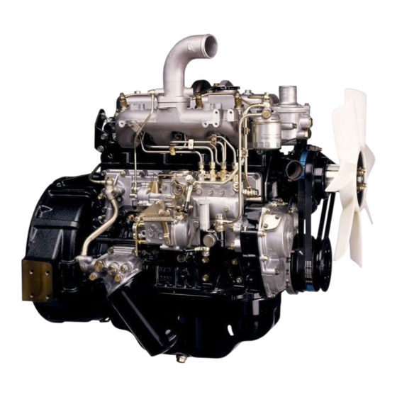
- Page 10 GENERAL INFORMATION 1–9 EXTERNAL VIEW MODEL AA-4BG1T, BB-4BG1T Note: Engine details may Turbocharger Oil filler cap Oil filler cap Turbocharger vary depending on Nozzle holder the specifications. Alternator Flywheel housing Injection pump Cylinder head cover Nozzle holder Partial oil filter...
- Page 11 GENERAL INFORMATION 1–11 EXTERNAL VIEW MODEL BB-6BG1T Note: Engine details may vary depending on the specifications. Turbocharger Turbocharger Exhaust manifold Nozzle holder Alternator Flywheel housing Injection pump Cylinder head cover Nozzle holder Main oil filter Glow plug Inlet manifold Partial oil filter Air duct Oil filler cap Flywheel...
- Page 12 GENERAL INFORMATION 1–13 EXTERNAL VIEW MODEL AA-6BG1 Note: Engine details may vary depending on the specifications. Cylinder head Dipstick Alternator Flywheel housing Exhaust manifold Cylinder head cover Oil filter Oil filler cap Inlet manifold Glow plug Nozzle holder Flywheel Dipstick Oil filler cap Nozzle holder Inlet manifold...
- Page 13 GENERAL INFORMATION 1–15 TIGHTENING TORQUE SPECIFICATIONS The tightening torque values given in the table below are applicable to the bolts unless otherwise specified. STANDARD BOLT N·m (kgf·m/lb.ft) Bolt Identification Bolt Diameter × pitch (mm) M 6 × 1.0 3.9–7.8 (0.4–0.8/2.9–5.8) 4.9–9.8 (0.5–1.0/3.6–7.2) M 8 ×...
- Page 14 1–16 GENERAL INFORMATION TIGHTENING TORQUE SPECIFICATIONS The tightening torque values given in the table below are applicable to the bolts unless otherwise specified. FLANGED HEAD BOLT N·m (kgf·m/lb.ft) Bolt Identification Bolt Diameter × pitch (mm) M 6 × 1.0 4.6–8.5 (0.5–0.9/3.6–6.5) 6.6–12.2 (0.6–1.2/4.3–8.7) M 8 ×...
- Page 15 GENERAL INFORMATION 1–17 ANGULAR NUT AND BOLT TIGHTENING METHOD 1. Carefully wash the nuts and bolts to remove all oil and grease. 2. Apply a coat of molybdenum disulfide grease to the threads and setting faces of the nuts and bolts. 3.
- Page 16 1–18 GENERAL INFORMATION Draw another line (C-D) on the face of each of the parts to be clamped. This line should be an exten- sion of the line [A-B]. Line Draw another line [F-G] on the face of each of the parts to be clamped.
- Page 17 GENERAL INFORMATION 1–19 MAJOR PART FIXING NUTS AND BOLTS Cylinder Head and Cover N·m (kgf·m/lb.ft) 7.8–9.8 (0.8–1.0/5.8–7.2) 5.9–16 (0.6–1.6/4.3–12) 42–62 69→88 →90°–120° (4.3–6.3/31–46) (7.0/51)→(9.0/65) Apply MoS grease 20–25 (2.0–2.5/14–18) Glow plug 42–62 (4.3–6.3/31–46) ..Molybdenum disulfide paste.
- Page 18 1–20 GENERAL INFORMATION Cylinder Body N·m (kgf·m/lb.ft) 42–62 (4.3–6.3/31–46) 21–30 (2.1–3.1/15–22) 21–30 (2.1–3.1/15–22) 21–30 (2.1–3.1/15–22) 226–245 (23–25/166–181) Apply engine oil 16–25 (1.6–2.6/12–19)
- Page 19 GENERAL INFORMATION 1–21 Oil Pan and Dipstick N·m (kgf·m/lb.ft) 25–30 (2.6–3.1/19–22) 21–30 (2.1–3.1/15–22) 69–88 (7–9/51–65)
- Page 20 1–22 GENERAL INFORMATION Camshaft and Rocker Arm N·m (kgf·m/lb.ft) 25–35 (2.6–3.6/19–26) 20–29 (2.0–3.0/15–22) 25–35 (2.6–3.6/19–26) 20–29 (2.0–3.0/15–22) 21–30 (2.1–3.1/15–22) 21–30 (2.1–3.1/15–22) 142–172 (14.5–17.5/105–127) Lubricate with engine oil 44–64 (4.5–6.5/33–47) 42–62 (4.3–6.3/31–46)
- Page 21 GENERAL INFORMATION 1–23 Crankshaft, Piston, and Flywheel N·m (kgf·m/lb.ft) →60°–90° (4/29) Apply MoS grease 539–637 382–481 197–240 142–172 (55–65/378–470) (39–49/282–354) (20.1–24.5/145–177) (14.5–17.5/105–127) Apply MoS grease Apply engine oil...
- Page 22 1–24 GENERAL INFORMATION Thermostat and Thermostat Housing N·m (kgf·m/lb.ft) 21–30 (2.1–3.1/15–22) 42–62 (4.3–6.3/31–46) 42–62 (4.3–6.3/31–46)
- Page 23 GENERAL INFORMATION 1–25 Intake and Exhaust Manifold N·m (kgf·m/lb.ft) 21–30 (2.1–3.1/15–22) 42–62 (4.3–6.3/31–46) 22–31 (2.2–3.2/16–23) 21–30 (2.1–3.1/15–22) 14–24 (1.4–2.4/10–17) 25–31 (2.6–3.2/19–23) 16–25 (1.6–2.6/12–19)
- Page 24 1–26 GENERAL INFORMATION Timing Gear Case and Flywheel Housing N·m (kgf·m/lb.ft) 21–30 (2.1–3.1/15–22) 147–167 (15–17/108–123) Outer side 21–30 (2.1–3.1/15–22) 14–24 (1.4–2.4/10–17) 147–167 (15–17/108–123) 21–30 (2.1–3.1/15–22) Inner side...
- Page 25 GENERAL INFORMATION 1–27 Oil Cooler, Oil Filter, and Oil Pump N·m (kgf·m/lb.ft) Refer to the section MAINTENANCE 30–50 (3.1–5.1/22–37) 42–62 (4.3–6.3/31–46) 42–62 (4.3–6.3/31–46) 21–30 (2.1–3.1/15–22) 14–24 (1.4–2.4/10–17) 16–25 (1.6–2.6/12–19)
- Page 26 1–28 GENERAL INFORMATION Fuel System N·m (kgf·m/lb.ft) 16–18 (1.6–1.8/12–13) 33–49 (3.4–5.0/25–36) 17–21 33–49 42–62 (1.7–2.1/12–15) (3.4–5.0/25–36) (4.3–6.3/31–46) 16–18 (1.6–1.8/12–13) 16–18 (1.6–1.8/12–13) 28–32 (2.9–3.3/21–24) 16–18 (1.6–1.8/12–13) 21–30 (2.1–3.1/15–22) 3.9–7.8 (0.4–0.8/2.9–5.8)
- Page 27 GENERAL INFORMATION 1–29 Turbocharger N·m (kgf·m/lb.ft) 16–25 (1.6–2.6/12–19) 42–62 (4.3–6.3/31–46) 22–31 (2.2–3.2/16–23) 28–46 (2.9–4.7/21–34) 16–25 (1.6–2.6/12–19)
- Page 28 1–30 GENERAL INFORMATION IDENTIFICATIONS MODEL IDENTIFICATION Engine Serial Number The engine number is stamped on the front left hand side of the cylinder body. Engine serial number INJECTION PUMP IDENTIFICATION Injection Pump Number Injection volume should be adjusted after referring to the adjustment data applicable to the injection pump installed.
- Page 29 MAINTENANCE 2–1 SECTION 2 MAINTENANCE TABLE OF CONTENTS ITEM PAGE Lubricating system ..................2– 2 Fuel system .
- Page 30 2–2 MAINTENANCE LUBRICATING SYSTEM Main Oil Filter Replacement Cartridge (Spin-On) Type Removal Removal and Installer: Filter Wrench 1. Loosen the used oil filter by turning it counterclock- wise with the filter wrench. 2. Discard the used oil filter. Installation 1. Wipe the oil filter mounting face with a clean rag. This will allow the new oil filter to seat properly.
- Page 31 MAINTENANCE 2–3 FUEL SYSTEM Fuel Filter Replacement Cartridge (Spin-On) Type Removal 1. Loosen the fuel filter by turning it counterclockwise with the filter wrench or your hand. Discard the used filter. Filter Wrench 2. Wipe the fuel filter fitting face clean with a rag. This will allow the new fuel filter to seat properly.
- Page 32 2–4 MAINTENANCE Installation 1. Apply a light coat of engine oil to the O-ring. 2. Supply fuel to the new fuel filter. This will facilitate air bleeding. 3. Turn in the new fuel filter until the filter O-ring is fit- ted against the sealing face.
- Page 33 MAINTENANCE 2–5 MPa (kgf/cm /psi) Injection Starting 18.1 (185/2630) Pressure WARNING TEST FLUID FROM THE NOZZLE TESTER WILL SPRAY OUT UNDER GREAT PRESSURE. IT CAN EASILY PUNCTURE A PERSON'S SKIN. KEEP YOUR HANDS AWAY FROM THE NOZZLE TESTER AT ALL TIMES. Spray Condition Check (During Injection Nozzle Tester Operation) 1.
- Page 34 2–6 MAINTENANCE Strainer Water Separator (Water Sedimentor) (Optional Equipment) Check the water separator float 1 level. If the float 1 has reached level 2, loosen the drain plug 3 (at the bottom side of the water separator) to drain the water. N·m (kgf·m/ft.lb) Drain Plug Torque 9–15 (0.9–1.5/7–11)
- Page 35 MAINTENANCE 2–7 COOLING SYSTEM Depress here Cooling Fan Drive Belt 98N (10kgf/22lb) Adjustment Check the cooling fan drive belt for cracking and Deflection other damage. Check the drive belt tension by exerting a force of 98N (10kgf/22lb) midway between the fan pulley 2 and the alternator 3.
- Page 36 2–8 MAINTENANCE 1. Bring the piston in either the No. 1 cylinder or the No. 6 cylinder to Top Dead Center on the compres- sion stroke by turning the crankshaft until the TDC notched line on the crankshaft pulley is aligned with the timing pointer.
- Page 37 MAINTENANCE 2–9 N·m (kgf·m/ft.lb) Front Rocker Arm Screw Lock 21–30 (2.1–3.1/15–22) Nut Torque When No.6 cylinder at TDC compression stroke Note: Front The valve clearance adjustment procedure for the 4BG1 engines is identical to that for the 6BG1 engines. Only the number of cylinders is different.
- Page 38 2–10 MAINTENANCE Checking Procedure 1. Align the crankshaft pulley TDC mark with the pointer. Remove the inspection hole cover at the front of the injection pump on the timing gear case cover. Check the alignment between the pointer 4 on the injection pump gear nut lock plate and the projec- tion area mark 3 on the injection pump gear case.
- Page 39 MAINTENANCE 2–11 6. Hold the fuel control lever at the fully open position. 7. Slowly turn the crankshaft pulley clockwise, at the same time, continue to feed the fuel with pumping the priming pump. When the fuel stop to flow out from the No. 1 deliv- ery valve holder, stop the pump instantaneously.
- Page 40 ISUZU engine service outlet for the specifications applic- able to your engine. These specifications have been set by ISUZU and the OEM manufacturer. 9. Remove the delivery valve holder from the No. 1 plunger.
- Page 41 MAINTENANCE 2–13 5. Do a fine injection pump position adjustment, while continue the pumping operation to feed the fuel, and stop to pivot the injection pump when the fuel stop to flow out from the No. 1 delivery valve holder. 6.
- Page 42 2–14 MAINTENANCE 3. Perform the operations described on page 2-10, 11 paragraphs 3, 4, 5, 6. 4. Slowly turn the coupling counterclockwise (viewed from the timing gear case). At the same time, operate the priming pump to feed fuel to the No. 1 injection pump plunger. Visually check that fuel is being fed (from the top of the delivery valve holder).
- Page 43 MAINTENANCE 2–15 COMPRESSION PRESSURE MEASUREMENT Operate the engine to warm-up until the coolant temperature reaches to 75°C (167°F). Remove all of the glow plugs and the injection pipes. Attach a compression gauge to the No. 1 cylinder glow plug installation threads. Note: Compression gauge adaptor Compression pressure may be measured starting at any...
- Page 44 2–16 MAINTENANCE TURBOCHARGER INSPECTION 1. Check the air intake duct connections for air leakage. 2. Check the air duct connections for air leakage. 3. Check the exhaust duct connections for smoke leak- age. 4. Check the turbocharger mounting nuts for loose- ness.
- Page 45 MAINTENANCE 2–17 ENGINE REPAIR KIT (FOR NATURALLY ASPIRATED ENGINES) 8 18 VIEW “A” 1. Cylinder head gasket 16. Gear case to cylinder block gasket 2. Cylinder head cover gasket 17. Cover to timing gear case gasket 3. Inlet manifold gasket 18.
- Page 46 2–18 MAINTENANCE ENGINE REPAIR KIT (FOR TURBOCHARGED ENGINES) 11 6 21 17 VIEW (A) 1. Cylinder head gasket 19. Oil pipe joint gasket 2. Cylinder head cover gasket 20. Joint bolt gasket 3. Cylinder head cover nut gasket 21. Oil pipe gasket 4.
- Page 47 MAINTENANCE 2–19 RECOMMENDED LUBRICANTS ENGINE TYPE TYPES OF LUBRICANTS (API) Diesel engine oil Without turbocharger & With turbocharger CD grade ENGINE OIL VISCOSITY CHART ENGINE OIL VISCOSITY GRADE – AMBIENT TEMPERATURE [Single grade] SAE 40, 50 SAE 20, 20W SAE 10W SAE 30 –30°C –15°C...
- Page 48 MEMO...
- Page 49 ENGINE ASSEMBLY I 3–1 SECTION 3 ENGINE ASSEMBLY I (DISASSEMBLY) TABLE OF CONTENTS ITEM PAGE External parts disassembly steps............... . 3– 2 Major components.
- Page 50 3–2 ENGINE ASSEMBLY I EXTERNAL PARTS DISASSEMBLY STEPS (Right-hand side) MODEL BB-6BG1T Disassembly Steps 1. Fan guide 10. Oil pipe; injection pump to cylinder 2. Cooling fan body 3. Not installed 11. Not installed 4. Intake pipe 12. Oil pipe; filter to oil cooler 5.
- Page 51 ENGINE ASSEMBLY I 3–3 MODEL BB-4BG1T Disassembly Steps 1. Cooling fan 9. Oil pipe; injection pump to cylinder 2. Not installed body 3. Intake pipe 10. Not installed 4. Fuel return pipe 11. Oil pipe; filter to oil cooler 5. Fuel pipe; fuel filter to injection 12.
- Page 52 3–4 ENGINE ASSEMBLY I Important Operations 12. Injection Pump with Injection Pump Gear Use the shipping plugs (or something similar) to seal the injection pump delivery valve ports. This will prevent the entry of foreign material. Flange Mounted Injection Pump Removal 1) Remove the injection pump flange bolts.
- Page 53 ENGINE ASSEMBLY I 3–5 EXTERNAL PARTS DISASSEMBLY STEPS (Left-hand side) MODEL BB-6BG1T Disassembly Steps 1. Dipstick and guide tube 6. Gasket 2. Air breather 7. Starter 3. Oil feed pipe 8. Fan belt 4. Oil drain pipe 9. Alternator 5. Turbocharger 10.
- Page 54 3–6 ENGINE ASSEMBLY I MODEL BB-4BG1T Disassembly Steps 1. Dipstick and guide tube 7. Gasket 2. Air breather 8. Starter 3. (Not installed) 9. Fan belt 4. Oil feed pipe 10. Alternator 5. Oil drain pipe 11. Fan pulley 6. Turbocharger 12.
- Page 55 ENGINE ASSEMBLY I 3–7 MAJOR COMPONENTS - I ★ 6 ★ ★ : Repair kit Disassembly Steps 1. Rubber hose ; water by-pass 9. Oil pump driving pinion 2. Rocker arm shaft assembly 10. Starting handle nut 3. Push rod 11. Taper bushing 4.
- Page 56 3–8 ENGINE ASSEMBLY I 6B series Important Operations Rocker Arm Shaft Loosen the rocker arm shaft fixing bolts a little at a time in numerical sequence as specified. 4B series Front Cylinder Head Bolts 6B series Loosen the cylinder head bolts a little at a time in the numerical order shown in the illustration.
- Page 57 ENGINE ASSEMBLY I 3–9 11. Taper Bushing (6B series only) Taper bushing Remover: 9-8521-0122-0 Use the taper bushing remover to remove the crank- shaft end taper bushing. Crankshaft Pulley Taper bushing remover 15. Flywheel Loosen the flywheel bolt a little at a time in the numerical order as specified.
- Page 58 3–10 ENGINE ASSEMBLY I MAJOR COMPONENTS - II ★ ★ ★ ★ : Repair kit Disassembly Steps 1. Oil cooler 9. Timing gear case 2. Oil pan 10. Idler gear shaft 3. Oil pump and coupling 11. Crankshaft bearing cap 4.
- Page 59 ENGINE ASSEMBLY I 3–11 Important Operations Idler Gear Measure the following points before disassembly. mm (in) Standard Limit Idler Gear End 0.128–0.185 Play (0.005–0.0070) (0.008) Feeler gauge mm (in) Standard Limit Timing Gears 0.10–0.17 Backlash (0.004–0.007) (0.012) Includes the crankshaft gear, the camshaft gear, and the idler gear.
- Page 60 3–12 ENGINE ASSEMBLY I ROCKER ARM, AND ROCKER ARM SHAFT DISASSEMBLY STEPS Disassembly Steps 1. Bracket 3. Spring 2. Rocker arm 4. Rocker arm shaft...
- Page 61 ENGINE ASSEMBLY I 3–13 CYLINDER HEAD DISASSEMBLY STEPS ★ ★ ★ ★ : Repair kit Disassembly Steps 1. Exhaust manifold and gasket 7. Spring seat (upper) or *Valve rotator (if so equipped) 2. Intake manifold and gasket 8. Valve spring 3.
- Page 62 3–14 ENGINE ASSEMBLY I PISTON AND CONNECTING ROD DISASSEMBLY STEPS Disassembly Steps 1. Piston rings 4. Piston 2. Snap ring 5. Connecting rod bearing 3. Piston pin and connecting rod...
- Page 63 ENGINE ASSEMBLY I 3–15 Important Operation Note: Remove any carbon deposits from the upper part of the cylinder bore. Carbon deposits This will prevent damage to the piston and the piston rings when they are removed from the cylinder bore. Piston Rings Piston ring remover Use a piston ring remover to remove the piston...
- Page 64 MEMO...
- Page 65 ENGINE ASSEMBLY II 4–1 SECTION 4 ENGINE ASSEMBLY II (INSPECTION & REPAIR) TABLE OF CONTENTS ITEM PAGE Cylinder head ....................4– 2 Valve guide.
- Page 66 4–2 ENGINE ASSEMBLY II INSPECTION AND REPAIR Make the necessary adjustments, repairs, and part replacements if excessive wear or damage is discov- ered during inspection. CYLINDER HEAD Cylinder Head Lower Face Warpage Use a straight edge and a feeler gauge to measure the four sides and the two diagonals of the cylinder head lower face.
- Page 67 ENGINE ASSEMBLY II 4–3 VALVE GUIDE Valve Stem and Valve Guide Clearance Measuring Method - 1 1. With the valve stem inserted in the valve guide, set the dial indicator needle to "0". 2. Move the valve head from side to side Note the total dial indicator reading (TIR).
- Page 68 4–4 ENGINE ASSEMBLY II Valve Depression 1. Install the valve 1 to the cylinder head 2. 2. Use a depth gauge or a straight edge with steel rule to measure the valve depression from the cylinder head lower surface. If the measured value exceeds the specified limit, the valve seat insert and/or valve must be replaced.
- Page 69 ENGINE ASSEMBLY II 4–5 Use a screwdriver 3 to pry the valve seat insert free. Take care not to damage the cylinder head 4. Carefully remove carbon and other foreign material from the cylinder head insert bore. Valve Seat Installation 1.
- Page 70 4–6 ENGINE ASSEMBLY II Angle Location Standard Intake Valve Seat Angle B 45° Exhaust Valve Seat Angle B 45° Note: Use an adjustable valve cutter pilot. Do not allow the cutter pilot to wobble inside the valve guide. 3. Apply abrasive compound to the valve seat insert surface.
- Page 71 ENGINE ASSEMBLY II 4–7 Valve Spring Inclination Use a surface plate and a square to measure the valve spring inclination. If the measured value exceeds the specified limit, the valve spring must be replaced. mm (in) Standard Limit Valve Spring less than Inclination 1.9 (0.075)
- Page 72 4–8 ENGINE ASSEMBLY II Use a dial indicator to measure the clearance between the tappet and cylinder body tappet travelling bore. mm (in) Standard Limit Tappet and Tappet 0.020–0.054 Travelling Bore (0.001–0.002) (0.004) Clearance PUSH ROD Use a filler gauge to measure the valve push rod run out.
- Page 73 ENGINE ASSEMBLY II 4–9 Rocker Arm Shaft and Rocker Arm Clearance 1. Use a vernier caliper to measure the rocker arm bushing inside diameter. mm (in) Standard Limit Rocker Arm Bushing 19.01–19.03 19.05 Inside Diameter (0.749–0.750) (0.751) 2. Measure the rocker arm shaft outside diameter. Replace either the rocker arm or the rocker arm shaft if the clearance exceeds the specified limit.
- Page 74 4–10 ENGINE ASSEMBLY II 2. Use a dial indicator to measure the idler gear inside diameter. mm (in) Standard Limit Idler Gear and Idler 0.025–0.085 Gear Shaft Clearance (0.001–0.003) (0.008) CAMSHAFT Use the camshaft bearing remover and installer to remove camshaft bearing from the cylinder body. Camshaft Bearing Remover and Installer: 9-8523- 1818-0 Measure the clearance between the cam journal and...
- Page 75 ENGINE ASSEMBLY II 4–11 5. Place the camshaft on a measuring stand. Use a dial indicator to measure the camshaft runout. Note the total indicator reading (TIR). If the measured run-out exceeds the specified limit, the camshaft must be replaced. mm (in) Limit Camshaft Run-Out TIR...
- Page 76 4–12 ENGINE ASSEMBLY II Cylinder Liner Projection Inspection 1. Hold a straight edge 1 along the top edge of the cylinder liner to be measured. 2. Use a feeler gauge 2 to measure each cylinder liner projection. mm (in) Standard Cylinder Liner Projection 0.03–0.10 (0.001–0.004) The difference in the cylinder liner projection height...
- Page 77 ENGINE ASSEMBLY II 4–13 Cylinder Bore Measurement Cylinder Liner Grade Selection The term "grade" refers to the cylinder body inside diam- eter and the cylinder liner outside diameter combination. Measure the cylinder body inside diameter and select the appropriate cylinder liner grade. Loose fitting cylinder liners (the liner is too small for the cylinder bore) will adversely affect engine cooling effi- ciency and may lead to serious engine damage.
- Page 78 4–14 ENGINE ASSEMBLY II Cylinder Liner Outside Diameter Measurement 1. Take measurements at measuring point 1, 2, and Measuring Points mm (in): 1 20.0 (0.788) 2 105.0 (4.137) 3 195.0 (7.683) 2. Calculate the average value of the 6 measurements to determine the correct cylinder liner grade.
- Page 79 ENGINE ASSEMBLY II 4–15 Cylinder Liner Installation 1. Carefully wipe away any foreign material from the cylinder liner inside and outside surfaces and the cylinder bore. 2. Use new kerosene or diesel oil to thoroughly clean the cylinder liner and bore surfaces. 3.
- Page 80 4–16 ENGINE ASSEMBLY II Cylinder Liner Bore Measurement 1. Locate the two measuring points. Cylinder Liner Measuring Point 1: 20 mm (0.788 in) Cylinder Liner Measuring Point 2: 105 mm (4.173 in) 2. Measure the cylinder liner bore at measuring point 1 and 2 in four different directions (W–W, X–X, Y–Y, and Z–Z).
- Page 81 ENGINE ASSEMBLY II 4–17 Piston Outside Diameter Measure the piston outside diameter at the measuring piston shown in the illustration. Piston Grade (For service parts) mm (in) 104.959–104.974 104.975–104.990 (4.1322–4.1328) (4.1329–4.1335) Cylinder Liner Bore and Piston Clearance (For service parts) mm (in) Cylinder Liner Bore and 0.051–0.085...
- Page 82 4–18 ENGINE ASSEMBLY II Piston Ring Gap 1. Insert the piston ring horizontally (in the position it would assume if it were installed to the piston) into the cylinder liner. 2. Use an inverted piston to push the piston ring into the cylinder liner until it reaches either measuring point 1 or measuring point 2.
- Page 83 ENGINE ASSEMBLY II 4–19 PISTON PIN Piston Pin Outside Diameter Use a micrometer to measure the piston pin outside diameter at several points. If the measured piston pin outside diameter exceeds the specified limit, the piston pin must be replace. mm (in) Standard Limit...
- Page 84 4–20 ENGINE ASSEMBLY II CONNECTING ROD Connecting Rod Alignment Use a connecting rod aligner to measure the connecting rod’s twist distortion and parralelism between the rod’s large and small ends. If the measured value exceeds the limit, replace the connecting rod. Connecting Rod Alignment (Per Length of 100 mm (3.94 in) mm (in)
- Page 85 ENGINE ASSEMBLY II 4–21 Connecting Rod Bushing Installation Use the connecting rod bushing installer to install the connecting rod bushing. Connecting Rod Bushing Installer: 9-8523-1369-0 (J-29765) Note: The connecting rod bushing oil port must be aligned with the connecting rod oil port. 3.
- Page 86 4–22 ENGINE ASSEMBLY II CRANKSHAFT Crankshaft and Bearing Inspection 1. Inspect the crankshaft journal surfaces and the crank pin surfaces for excessive wear and damage. 2. Inspect the oil seal fitting surfaces of the crankshaft front and rear ends for excessive wear and damage. 3.
- Page 87 ENGINE ASSEMBLY II 4–23 mm (in) Standard 63.924–63.944 Crankshaft Pin Diameter (2.5167–2.5175) 4. Measure the crankshaft journal outside diameter (and/or the crankpin outside diameter) and the bear- ing inside diameters to determine the bearing clear- ance. Crankshaft Journal and Bearing Clearances If the bearing clearance exceeds the specified limit, the crankshaft must be reground (except 4BD1T, 6BD1T, 6BG1 and 6BG1T) and/or the bearing must be replaced.
- Page 88 4–24 ENGINE ASSEMBLY II Crankshaft Journal Bearing Inside Diameter 1. Install the main bearing cap with bearings to the cylinder body with the specified torque and facing the arrow mark on the bearing cap toward front. Place them in order of punched cylinder numbers. 2.
- Page 89 Crankshaft Regrinding Note: Crankshaft for AA-4BG1T, BB-4BG1T, AA-6BG1 and BB- 6BG1T can not be reground because it is finished with TUFFTRIDE method. For the crankshaft on AA-4BG1T, BB-4BG1T, AA-6BG1...
- Page 90 4–26 ENGINE ASSEMBLY II Plastigage Clearance Measurements This is another method to measure the crankjournal bearing clearance. Crankshaft Journal Bearing Clearance 1. Clean the cylinder body, the journal bearing fitting portions, the bearing cap, and the inside the outside surfaces of the bearing. 2.
- Page 91 Ammonium cuprous Inspection not be applied to chloride area around oil Model AA-4BG1T, BB-4BG1T, AA-6BG1 and BB-6BG1T port Face in contact 1. Use an organic cleaner to thoroughly clean the with crank pin crankshaft. There must be no traces of oil on the or journal surfaces to be inspected.
- Page 92 4–28 ENGINE ASSEMBLY II Judgement 1. Wait for thirty to forty seconds. If there is no discoloration after thirty or forty sec- onds, the crankshaft is usable. If discoloration appears (the surface being tested will become the color of copper), the crankshaft must be replaced.
- Page 93 ENGINE ASSEMBLY II 4–29 Crankshaft Gear Replacement Removal Remover Use the crankshaft gear remover to remove the crank- shaft gear. Crankshaft Gear Remover: 9-8521-0141-0 Installation Use the crankshaft gear installer to install the crankshaft gear. Crankshaft Gear Installer: 9-8522-0033-0 Installer FLYWHEEL AND FLYWHEEL HOUSING Ring Gear Inspection Inspect the ring gear.
- Page 94 MEMO...
- Page 95 ENGINE ASSEMBLY III 5–1 SECTION 5 ENGINE ASSEMBLY III (REASSEMBLY) TABLE OF CONTENTS ITEM PAGE Piston and connecting rod reassembly steps............5– 2 Cylinder head reassembly steps .
- Page 96 5–2 ENGINE ASSEMBLY III PISTON AND CONNECTING ROD REASSEMBLY STEPS MIRROR COMPONENT Reassembly Steps Piston Piston ring Connecting-rod Connecting rod bearing Piston pin, Snap ring...
- Page 97 ENGINE ASSEMBLY III 5–3 PISTON AND CONNECTING ROD Conventional piston heater Important Operations 1. Piston Use a piston heater to heat the pistons to approxi- mately 60°C (140°F). 2. Connecting Rod 1) Install the connecting rod to the piston with set- ting the marks as illustrated.
- Page 98 5–4 ENGINE ASSEMBLY III CYLINDER HEAD REASSEMBLY STEPS ★ ★ ★ ★ : Repair kit Reassembly Steps 1. Valve stem oil seal Thermostat housing and gasket 2. Intake and exhaust valves Thermostat 3. Spring seat (Lower) Water outlet pipe 4. Intake and exhaust valve springs 10.
- Page 99 ENGINE ASSEMBLY III 5–5 Important Operations Installer 1. Valve Stem Oil Seal 1) Lubricate the oil seals and valve stem sealing areas with engine oil. 2) Use a valve stem oil seal installer to install the oil seal. Valve Stem Oil Seal Installer: 1-85221-005-0 2.
- Page 100 5–6 ENGINE ASSEMBLY III 10. Intake Manifold and Gasket 1) Install the intake manifold gasket. Unchamfered corner The intake manifold gasket must be installed with its unchamfered corner facing up and to the front of the engine. Refer to the illustration. 2) Install the intake manifold.
- Page 101 ENGINE ASSEMBLY III 5–7 4BG1 4) Install either end of the distance tube to the spot facing (6B series engine only). Distance tube Spot facing...
- Page 102 5–8 ENGINE ASSEMBLY III ROCKER ARM AND ROCKER ARM SHAFT REASSEMBLY STEPS Reassembly Steps 1. Rocker arm shaft 3. Rocker arm 2. Spring 4. Bracket Important Operation 1. Rocker Arm Shaft The rocker arm shaft must be installed with the oil ports facing up.
- Page 103 ENGINE ASSEMBLY III 5–9 MAJOR COMPONENT REASSEMBLY STEPS I ★ ★ ★ ★ : Repair kit Reassembly Steps 1. Oil jet 9. Idler gear shaft 2. Crankshaft bearing (upper half) 10. Idler gear 3. Crankshaft 11. Piston and connecting rod 4.
- Page 104 5–10 ENGINE ASSEMBLY III Important Operations 1. Oil Jet Install the oil jets taking care not to damage the oil jet nozzles. N·m (kgf·m/lb.ft) Fit correctly With oil hole Oil Jet Torque 16–25 (1.6–2.6/12–19) and groove (upper) 2. Crankshaft Bearing (Upper Half) 5.
- Page 105 ENGINE ASSEMBLY III 5–11 N·m (kgf·m/lb.ft) Crankshaft Bearing Cap 226–245 (23.0–25.0/166–181) Bolt Torque 4) Check that the crankshaft turns smoothly by manually rotating it. Lubricate with engine oil 6. Timing Gear Case 1) Apply liquid gasket to the timing gear case sur- faces contacting the cylinder body.
- Page 106 5–12 ENGINE ASSEMBLY III 11. Piston and Connecting Rod Position the piston ring gaps as shown in the illus- tration. 1) Set the piston ring gaps as shown in the illustra- tion. 2) Lubricate the piston, the piston rings, and the connecting rod bearings with engine oil.
- Page 107 ENGINE ASSEMBLY III 5–13 13. Flywheel Housing 1) Apply a sealant to the shaded area of the illus- tration. 2) Install the flywheel housing. Tighten the flywheel housing bolts to the speci- fied torque. N·m (kgf·m/lb.ft) Outer Bolt 147–167(15.0–17.0/108–123) Flywheel Housing Bolt Torque Inner Bolt 21–30 (2.1–3.1/15–22)
- Page 108 5–14 ENGINE ASSEMBLY III MAJOR COMPONENT REASSEMBLY STEPS II ★11 ★ ★ : Repair kit Reassembly Steps 1. Flywheel 9. Tappet chamber cover 2. Injection pump and injection pump gear 10. Water pump 3. Oil thrower 11. Cylinder head gasket 4.
- Page 109 ENGINE ASSEMBLY III 5–15 Important Operations 1. Flywheel 1) Lubricate the flywheel bolt threads. 2) Install the flywheel. The crankshaft rear end dowel pin and the fly- wheel dowel hole must be aligned. Lubricate with 3) Tighten the flywheel bolts to the specified engine oil torque in the numerical order shown in the illus- tration.
- Page 110 5–16 ENGINE ASSEMBLY III 2. Install the air compressor 3. Tighten the air compressor mounting bolts. Mark After installing the air compressor, perform Step 3 of "Injection Pump and Injection Pump Gear Assembly" (on the following page). Refer to injection timing in section MAINTENANCE to check the injection timing for correctness.
- Page 111 ENGINE ASSEMBLY III 5–17 3) Carefully place the cylinder head on the cylinder 6B series body. 4) Tighten the cylinder head bolt as follows. 1) As cylinder head bolts have two kinds of length, install them at proper location. Front The shorter ones (4B series;...
- Page 112 5–18 ENGINE ASSEMBLY III 15. Rocker Arm and Rocker Arm Shaft 1) Check that the rocker arm shaft bracket lower surface oil port is free from obstruction. 13 9 2) Install the rocker arm shaft with the bracket to 12 14 the cylinder head.
- Page 113 ENGINE ASSEMBLY III 5–19 EXTERNAL PARTS REASSEMBLY STEPS (Left-hand side) Reassembly Steps 1. Cylinder head cover 7. Turbocharger 2. Fan pulley 8. Oil drain pipe 3. Alternator 9. Oil feed pipe 4. Fan belt 10. Air breather 5. Starter 11. Dipstick and guide tube 6.
- Page 114 5–20 ENGINE ASSEMBLY III 6B series Important Operations 1. Cylinder Head Cover 1) Check that the rocker arms, the rocker arm shafts, and the valve springs are thoroughly lubricated with engine oil. If required, relubricate these parts. 2) Place the cylinder head cover gasket on the cylinder head cover.
- Page 115 6BG1T 6BG1T Carefully position the gasket with the edged side facing up. 4BG1T 7. Turbocharger (AA-4BG1T, BB-4BG1T, BB-6BG1T) Semitighten the turbocharger mounting nuts. The nuts will be fully tightened after installation of the oil pipes. N·m (kgf·m/lb.ft) Turbocharger Mounting 6BG1T 42–62(4.3–6.3/31–46) Nut Torque 4BG1T 22–31(2.2–3.2/16–23)
- Page 116 5–22 ENGINE ASSEMBLY III 9. Oil Feed Pipe 1) Pre-lubricate the turbocharger with CD grade oil through the oil port shown by the arrow in the illustration. 2) Install the oil feed pipe and tighten the pipe flange bolts to the specified torque. N·m (kgf·m/lb.ft) Oil Feed Pipe Flange 16 –...
- Page 117 ENGINE ASSEMBLY III 5–23 EXTERNAL PARTS REASSEMBLY STEPS (Right-hand Side) MODEL 6BG1T Reassembly Steps 1. Glow plug 8. Fuel filter 2. Injection nozzle 9. Fuel pipe; feed pump to fuel filter 3. Injection pipe and fuel leak off pipe 10. Fuel pipe; fuel filter to injection 4.
- Page 118 5–24 ENGINE ASSEMBLY III Important Operation Dust cover 2. Injection Nozzle Install the injection nozzles with the injection nozzle gaskets. Be careful not to damage the nozzle tips. N·m (kgf·m/lb.ft) Injection Nozzle Bolt 17 – 21 (1.7 – 2.1/12 – 15) Torque Nozzle gasket 3.
- Page 119 ENGINE ASSEMBLY III 5–25 9. Fuel Pipe (Feed Pump to Fuel Filter) 10. Fuel Pipe (Fuel Filter to Injection Pump) 11. Fuel Return Pipe Install the fuel pipes and tighten the fuel pipe joint bolts to the specified torque. Take care not to interchange the check valves and joint bolts.
- Page 120 5–26 ENGINE ASSEMBLY III Fan and Fan guide clearance Adjust the clearance between the fan and fan guide. mm (in) Clearance between 4 – 8 (0.157 – 0.315) fan and fan guide Injection Timing Adjustment Check that the fuel injection timing is correct. Refer to "MAINTENANCE"...
- Page 121 ENGINE ASSEMBLY III 5–27 ENGINE TUNING OPERATION After reassembly, the engine must be tuned. This will ensure that the engine operates at its maximum effi- ciency. 1. Mount the engine on a test bench. 2. Fill the engine with the specified oil. 3.
- Page 122 5–28 ENGINE ASSEMBLY III 9. Crank the engine with the starter (non-ignition oper- ation) for about twenty seconds. This will prelubricate the engine internal compo- nents. 10. Start the engine and allow it to run at 750 to 800 rpm for five minutes.
- Page 123 ENGINE ASSEMBLY III 5–29 ENGINE SECTIONAL VIEW For your reference: Note: This sectional drawing is based on 6BG1 standard engine.
- Page 124 MEMO...
- Page 125 LUBRICATING SYSTEM 6–1 SECTION 6 LUBRICATING SYSTEM TABLE OF CONTENTS ITEM PAGE General description ..................6– 2 Oil pump.
- Page 126 6–2 LUBRICATING SYSTEM GENERAL DESCRIPTION Full flow filter Oil pressure Starter and oil filter switch Battery 4BG1T warning light By-pass 6BG1T valve By-pass Valve opening Oil pressure switch valve pressure 98 kPa Cylinder body oil gallery Paper cooler filter Valve opening Tim- Valve opening pressure Crank...
- Page 127 LUBRICATING SYSTEM 6–3 OIL PUMP DISASSEMBLY Disassembly Steps Strainer Driven gear Suction pipe Drive shaft and gear Cover and dowel Driven gear shaft...
- Page 128 6–4 LUBRICATING SYSTEM INSPECTION REPAIR Make the necessary adjustments, repairs, and part replacements if excessive wear or damage is discov- ered during inspection. Visually inspect the disassembled parts for excessive wear and damage. Oil Pump Drive Gear Use a feeler gauge to measure the clearance between the oil pump cover (oil pump case) inside surface and the drive gear.
- Page 129 LUBRICATING SYSTEM 6–5 OIL COOLER DISASSEMBLY Disassembly Steps Oil cooler element O-ring; plug Element gasket By-pass valve spring By-pass valve plug By-pass valve INSPECTION AND REPAIR Make the necessary adjustments, repairs, and part replacements if excessive wear or damage is discov- ered during inspection.
- Page 130 6–6 LUBRICATING SYSTEM REASSEMBLY Reassembly Steps 1. By-pass valve 4. By-pass valve plug 2. By-pass valve spring 5. Element gasket 3. O-ring; plug 6. Oil cooler element Important Operation 6. Oil Cooler Element Install the oil cooler element to the oil cooler, and tighten the cooler element fixing nuts to the speci- fied torque.
- Page 131 COOLING SYSTEM 7–1 SECTION 7 COOLING SYSTEM TABLE OF CONTENTS ITEM PAGE General description ..................7– 2 Thermostat.
- Page 132 7–2 COOLING SYSTEM GENERAL DESCRIPTION Water outlet pipe Thermostat Cylinder head Reserve tank Cylinder body Water pump This family of engines uses a pressurized, forced circulation cooling system with a V-belt driven centrifu- gal water pump and a wax pellet thermostat with jiggle valve.
- Page 133 COOLING SYSTEM 7–3 THERMOSTAT INSPECTION AND REPAIR Make the necessary adjustments, repairs, and part replacements if excessive wear or damage is discov- ered during inspection. Visually inspect the thermostat function referring Thermometer Section 2 MAINTENANCE in page 2-7. Agitating rod Wood piece...
- Page 134 MEMO...
- Page 135 FUEL SYSTEM 8–1 SECTION 8 FUEL SYSTEM TABLE OF CONTENTS ITEM PAGE General description ..................8– 2 Injection nozzle.
- Page 136 8–2 FUEL SYSTEM GENERAL DESCRIPTION This illustration is based on the 6BG1 engines. Nozzle holder Fuel filter Feed pump Water sedimentor Fuel tank Injection pump The fuel system consists of the fuel tank, the water sedimentor, the fuel filter, the injection pump, and the injection nozzle.
- Page 137 FUEL SYSTEM 8–3 INJECTION NOZZLE DISASSEMBLY Disassembly Steps 1. Nozzle holder cap nut 6. Retaining nut 2. Cap nut gasket 7. Injection nozzle 3. Nozzle adjusting screw 8. Injection pipe connector 4. Push rod spring 9. Connector gasket 5. Nozzle holder push rod 10.
- Page 138 8–4 FUEL SYSTEM INSPECTION AND REPAIR Make the necessary adjustments, repairs, and part replacements if excessive wear or damage is discov- ered during inspection. Push Rod Spring Check the push rod spring for wear, weakness, and cor- rosion. Nozzle Holder Push Rod 1.
- Page 139 FUEL SYSTEM 8–5 REASSEMBLY Reassembly Steps 1. Nozzle holder body 6. Nozzle holder push rod 2. Connector gasket 7. Push rod spring 3. Injection pipe connector 8. Nozzle adjusting screw 4. Injection nozzle 9. Cap nut gasket 5. Retaining nut 10.
- Page 140 8–6 FUEL SYSTEM Important Operation 3. Injection Pipe Connector N·m (kgf·m/lb.ft) Nozzle Connector Torque 49 – 59 (5.0 – 6.0/36 – 43) 4. Injection Nozzle There must be no oil on the contact surfaces of the injection nozzle and the injection nozzle holder. Clean these contact surfaces with diesel fuel before installation.
- Page 141 FUEL SYSTEM 8–7 10. Nozzle Holder Cap Nut N·m (kgf·m/lb.ft) Cap Nut Torque 29 – 39 (3.0 – 4.0/22 – 29)
- Page 142 Without this data, the Service Outlet will be unable to effectively service your injection pump. If you are unable to locate the data applicable to your injection pump, please contact ISUZU MO- TORS LTD through your machine supplier. 3. Do not remove the Identification Plate and Product Serial Number from the injection pump.
- Page 143 FUEL SYSTEM 8–9 INJ. PUMP CALIBRATION DATA Ass’y No. 000000–0000 Date : ENGINE MODEL 4BG1–T Company : ISUZU 0–00000–0000 Injection pump : PES4A Governor : EP/RSV Timing device : 000000–0000 000000–0000 1. Test Conditions : Pump rotation : clockwise (viewed from drive side) Nozzle &...
- Page 144 8–10 FUEL SYSTEM 3. Governor adjustment 000000–0000 Recommended speed droop adjustment screw position: 12 (notches from fully tightened position) Above 14.0 13.0 Rack limit Idle-sub spring setting Governor spring setting ±0.1 ±0.1 ±0.3 1100 1130 ±30 (430) (1120) 1210 Pump speed (r/min) Speed control lever angle Stop lever angle Idling...
- Page 145 Regarding the details of the turbocharger repair, refer the following workshop manual. Published by: MITSUBISHI HEAVY INDUSTRIES CO., LTD Title of the manual: MITSUBISHI TURBOCHARGERS (TD-04H FOR 4BG1T) Pub No. 99626-92110 Availability of the manual ISUZU MOTORS LIMITED will send the manual upon request through your machine supplier.
- Page 146 9–2 TURBOCHARGER GENERAL DESCRIPTION TD04H RHG6...
- Page 147 Refer to the illustration at the left. (1) Turbo Specification Number, Production Year and Turbo Spec. Month Serial No. RHG6 (2) Production Date, Daily Serial Number (3) ISUZU Parts Number Parts No. IHI Turbocharger (1) Serial Number (2) ISUZU Part Number Type...
- Page 148 9–4 TURBOCHARGER INSPECTION AND REPAIR If excessive wear or damage is discovered during inspection, the appropriate parts must be adjusted, repaired, or replaced. Damage or improper adjustment of the turbocharger will inhibit sufficient air flow to the engine, preventing it from delivering full performance. If the engine demonstrates a significant drop in perfor- mance, check for engine damage or wear.
- Page 149 AIR COMPRESSOR 10–1 SECTION 10 AIR COMPRESSOR TABLE OF CONTENTS ITEM PAGE General description ..................10– 2 Disassembly steps.
- Page 150 10–2 AIR COMPRESSOR GENERAL DESCRIPTION AIR COMPRESSOR SECTIONAL VIEW from Governer to Air tank from Air cleaner Main Data Piston ring configuration Two compression rings and one oil ring Theoretical air delivery amount 0.155 L/rev. Cylinder bore × stroke 70 (2.755) × 40 (1.574) mm (in) Maximum operating speed 1650...
- Page 151 AIR COMPRESSOR 10–3 DISASSEMBLY STEPS Disassembly Steps 1. Cylinder head and gasket 5. Bearing cover with oil seal 2. Cylinder body 6. Bearing 3. Piston 7. Connecting rod 4. Crankcase flange 8. Crankshaft and bearing Important Operation 2. Cylinder body 1) Remove the cylinder mounting flange bolts.
- Page 152 10–4 AIR COMPRESSOR INSPECTION AND REPAIR Make the necessary adjustments, repairs, and part replacements if excessive wear or damage is discov- ered during inspection. Cylinder Measure the uneven wear of the cylinder bore at the pis- ton skirt position mm (in) Limit Cylinder Bore Uneven Wear 0.2 (0.0079)
- Page 153 AIR COMPRESSOR 10–5 Measure the piston and the piston pin hole clearance. mm (in) Standard Limit Piston Pin and Piston 0.002–0.023 0.0040 Pin Hole Clearance (0.00008–0.00091) (0.00016) Measure the piston pin and the connecting rod small- end clearance. mm (in) Standard Limit Piston Pin and...
- Page 154 10–6 AIR COMPRESSOR REASSEMBLY STEPS Reassembly Steps 1. Crankshaft and bearing 5. Crankcase flange 2. Connecting rod 6. Piston 3. Bearing 7. Cylinder body 4. Bearing cover with oil seal 8. Cylinder head and gasket Important Operation 1. Crankshaft and bearings 1) Install the bearings to the crankshaft.
- Page 155 AIR COMPRESSOR 10–7 2. Connecting rod 1) Install the connecting rod bearing cap and tighten the cap bolts to the specified torque. N·m (kgf·m/lb.ft) Connecting Rod Cap 25 (2.5/18) Bolt Torque 4. Bearing cover 1) Remove the used O-ring from the bearing case and discard it.
- Page 156 MEMO...
- Page 157 ENGINE ELECTRICALS 11–1 SECTION 11 ENGINE ELECTRICALS TABLE OF CONTENTS ITEM PAGE Starter identification ..................11– 2 Starter main data and specifications .
- Page 158 11–2 ENGINE ELECTRICALS STARTER IDENTIFICATION The starter identification plate is attached to the starter motor outside yoke. The ISUZU part number, the manufacturer's code number, and other important information are stamped on the plate. Refer to the identification plate together with the "Main Data and Specifications" Tables and accompany- ing charts in this Manual when requesting service assistance from a qualified electrical repair shop.
- Page 159 ENGINE ELECTRICALS 11–3 STARTER MAIN DATA AND SPECIFICATIONS Isuzu Part No. 897225-1990 1-81100-3420 Manufacturer's code No. (HITACHI) S25-177 S25-172 Rated voltage Rated output (kW) Rating (Sec) Direction of rotation (Viewed from the pinion side) Clockwise Clockwise Clutch type Roller Roller...
- Page 160 11–4 ENGINE ELECTRICALS STARTER MOTOR SECTIONAL VIEW Magnetic switch Gear shaft (Internal gear) Yoke Shift lever Gear case Armature Brush ブラシ ブラシ Pinion Brush holder ブラシホルダ ブラシホルダ Pinion gap ピニオンギャップ ピニオンギャップ (0.3–1.5mm/0.012–0.059in.) (0.3〜1.5mm) (0.3〜1.5mm) Baffer spring Center bracket (2) Rear cover スルーボルト...
- Page 161 Refer to the identification plate together with the "Main Data and Specifications" Tables and accompany- ing charts in this Manual when requesting service assistance from a qualified electrical repair shop. If you are unable to locate the data applicable to your engine, please contact ISUZU MOTORS LIMITED through your machine supplier.
- Page 162 11–6 ENGINE ELECTRICALS MAIN DATA AND SPECIFICATIONS ALTERNATOR Isuzu Part No. 1-81200-5301 Manufacturer's code No. (MITSUBISHI) A004T05486 Rated voltage Rated output Rated speed (min 5000 Rated output at r.p.m (Amp./Volt/min 50/27/5000 No-load output at 0 Amp. (Volt/min 24/900 Direction of rotation as viewed...
- Page 163 ENGINE ELECTRICALS 11–7 ALTERNATOR SECTIONAL VIEW STARTER ROTOR RECTIFIER BEARING PULLEY BEARING IC REGULATOR REAR FRONT BRACKET BRACKET COIL ASSEMBLY (FIELD COIL) CHARGING CURCUIT ADDITIONAL DIODES INDICATOR LAMP DIODE TRIO STARTER COIL SWITCH BATTERY (24V) FIELD COIL IC REGULATOR ALTERNATOR...
- Page 164 MEMO...
- Page 165 TROUBLESHOOTING 12–1 SECTION 12 TROUBLESHOOTING TABLE OF CONTENTS ITEM PAGE Hard starting ....................12– 2 1) Starter inoperative .
- Page 166 12–2 TROUBLESHOOTING HARD STARTING STARTER INOPERATIVE Checkpoint Trouble Cause Remedy Neutral switch (If so equipped) Defective neutral switch Replace the neutral switch Loose battery cable terminals Clean and/or retighten the bat- Battery Poor connections due to rusting tery cable terminals Battery discharged or weak Recharge or replace the battery Fan belt loose or broken...
- Page 167 TROUBLESHOOTING 12–3 HARD STARTING STARTER OPERATES BUT ENGINE DOES NOT TURN OVER Checkpoint Trouble Cause Remedy Loose battery cable terminals Clean and/or retighten the bat- Battery Poor connections due to rusting tery cable terminals Battery discharged or weak Recharge or replace the battery Fan belt loose or broken Adjust or replace the fan belt Starter...
- Page 168 12–4 TROUBLESHOOTING HARD STARTING ENGINE TURNS OVER BUT DOES NOT START FUEL IS BEING DELIVERED TO THE INJECTION PUMP Checkpoint Trouble Cause Remedy Continued from the previous page Injection nozzle injection starting Adjust or replace the injection Injection nozzle pressure too low nozzle Improper spray condition Defective fuel injection nozzle...
- Page 169 TROUBLESHOOTING 12–5 HARD STARTING ENGINE TURNS OVER BUT DOES NOT START Checkpoint Trouble Cause Remedy Defective engine stop mechanism Replace the engine stop Engine stop mechanism control wire improperly adjusted mechanism (In-line pump) Adjust the control wire Defective fuel cut solenoid valve Replace the fuel cut solenoid (VE pump) valve...
- Page 170 12–6 TROUBLESHOOTING UNSTABLE LOW IDLING Checkpoint Trouble Cause Remedy Low idling system Low idling improperly adjusted Adjust the low idling Defective low idling speed Repair or replace the low idling Low idling speed control device control device speed control device Throttle control system Adjust the throttle control Throttle control system...
- Page 171 TROUBLESHOOTING 12–7 UNSTABLE LOW IDLING Checkpoint Trouble Cause Remedy Continued from the previous page Repair or replace the governor Injection pump Defective governor lever operation lever Regulator valve improperly Adjust or replace the regulator adjusted (VE pump only) valve Broken plunger spring Replace the plunger spring Worn plunger Replace the plunger assembly...
- Page 172 12–8 TROUBLESHOOTING UNSTABLE LOW IDLING Checkpoint Trouble Cause Remedy Continued from the previous page Valve clearance improperly Valve clearance Adjust the valve clearance adjusted Blown out cylinder head gasket Worn cylinder liner Compression pressure Piston ring sticking or broken Replace the related parts Improper seating between the valve and the valve seat...
- Page 173 TROUBLESHOOTING 12–9 INSUFFICIENT POWER Checkpoint Trouble Cause Remedy Clean or replace the air cleaner Air cleaner Clogged air cleaner element element Fuel Water particles in the fuel Replace the fuel Replace the fuel filter element or Fuel filter Clogged fuel filter element the fuel filter cartridge Repair or replace the fuel feed Fuel feed pump...
- Page 174 12–10 TROUBLESHOOTING INSUFFICIENT POWER Checkpoint Trouble Cause Remedy Continued from the previous page Injection pump Defective delivery valve Replace the delivery valve Defective timer Repair or replace the timer Adjust or replace the control Improper control lever operation lever Adjust the injection timing Defective injection timing Repair or replace the injection pump timer...
- Page 175 TROUBLESHOOTING 12–11 INSUFFICIENT POWER Checkpoint Trouble Cause Remedy Continued from the previous page Injection pump Worn roller tappet Replace the roller tappet Exhaust gas leakage from the Repair or replace the related Turbocharger exhaust system parts Air leakage from the intake system Defective turbocharger assembly Replace the turbocharger assembly Blown out cylinder head gasket...
- Page 176 12–12 TROUBLESHOOTING EXCESSIVE FUEL CONSUMPTION Checkpoint Trouble Cause Remedy Repair or replace the fuel system Fuel system Fuel leakage related parts Clean or replace the air cleaner Air cleaner Clogged air cleaner element element Low idling speed Poorly adjusted low idle speed Adjust the low idle speed Injection nozzle injection starting Adjust or replace the injection...
- Page 177 TROUBLESHOOTING 12–13 EXCESSIVE FUEL CONSUMPTION Checkpoint Trouble Cause Remedy Continued from the previous page Turbocharger Defective turbocharger assembly Replace the turbocharger assembly Valve clearance improperly Valve clearance Adjust the valve clearance adjusted Blown out cylinder head gasket Worn cylinder liner Compression pressure Piston ring sticking or broken Replace the related parts...
- Page 178 12–14 TROUBLESHOOTING EXCESSIVE OIL CONSUMPTION Checkpoint Trouble Cause Remedy Engine oil unsuitable Replace the engine oil Engine oil Too much engine oil Correct the engine oil volume Oil leakage from the oil seal Replace the oil seal and/or the Oil seal and gasket and/or the gasket gasket Air breather...
- Page 179 TROUBLESHOOTING 12–15 OVERHEATING Checkpoint Trouble Cause Remedy Cooling water Insufficient cooling water Replenish the cooling water Fan belt loose or cracked causing Fan belt Replace the fan belt slippage Defective radiator cap or clogged Replace the radiator cap or clean Radiator radiator core the radiator core...
- Page 180 12–16 TROUBLESHOOTING OVERHEATING Checkpoint Trouble Cause Remedy Continued from the previous page Fuel injection timing improperly Fuel injection timing Adjust the fuel injection timing adjusted...
- Page 181 TROUBLESHOOTING 12–17 WHITE EXHAUST SMOKE Checkpoint Trouble Cause Remedy Fuel Water particles in the fuel Replace the fuel Fuel injection timing Delayed fuel injection timing Adjust the fuel injection timing Blown out cylinder head gasket Worn cylinder liner Compression pressure Piston ring sticking or broken Replace the related parts Improper seating between the...
- Page 182 12–18 TROUBLESHOOTING DARK EXHAUST SMOKE Checkpoint Trouble Cause Remedy Clean or replace the air cleaner Air cleaner Clogged air cleaner element element Injection nozzle injection starting Adjust or replace the injection Injection nozzle pressure too low nozzle Improper spray condition Fuel injection timing improperly Fuel injection timing Adjust the fuel injection timing...
- Page 183 TROUBLESHOOTING 12–19 OIL PRESSURE DOES NOT RISE Checkpoint Trouble Cause Remedy Improper viscosity engine oil Replace the engine oil Engine oil Too much engine oil Correct the engine oil volume Defective oil pressure gauge or Repair or replace the oil pres- Oil pressure gauge or unit unit sure gauge or unit...
- Page 184 12–20 TROUBLESHOOTING OIL PRESSURE DOES NOT RISE Checkpoint Trouble Cause Remedy Continued from the previous page Worn camshaft and camshaft Replace the camshaft and the Camshaft bearing camshaft bearings Replace the crankshaft and/or Crankshaft and bearings Worn crankshaft and bearings the bearings...
- Page 185 TROUBLESHOOTING 12–21 ABNORMAL ENGINE NOISE Engine Knocking Checkpoint Trouble Cause Remedy Check to see that the engine has been thoroughly warmed up before beginning the troubleshooting procedure. Fuel Fuel unsuitable Replace the fuel Fuel injection timing improperly Fuel injection timing Adjust the fuel injection timing adjusted Improper injection nozzle starting...
- Page 186 12–22 TROUBLESHOOTING ABNORMAL ENGINE NOISE Gas Leakage Noise Checkpoint Trouble Cause Remedy Continued from the previous page Loosely connected exhaust mani- Tighten the exhaust manifold Exhaust manifold fold and/or glow plugs connections Cylinder head gasket Damaged cylinder head gasket Replace the cylinder head gasket Continuous Noise Fan belt Loose fan belt...
- Page 187 TROUBLESHOOTING 12–23 ABNORMAL ENGINE NOISE Slapping Noise Checkpoint Trouble Cause Remedy Valve clearance improperly Valve clearance Adjust the valve clearance adjusted Rocker arm Damaged rocker arm Replace the rocker arm Flywheel Loose flywheel bolts Retighten the flywheel bolts Worn or damaged crankshaft Replace the crankshaft and/or Crankshaft and thrust bearings and/or thrust bearings...
- Page 188 MEMO...
- Page 189 SPECIAL TOOL LIST 13–1 SECTION 13 SPECIAL TOOL LIST TABLE OF CONTENTS ITEM PAGE Special tool list................... . 13– 2...
- Page 190 13–2 SPECIAL TOOL LIST SPECIAL TOOL LIST ITEM NO. ILLUSTRATION PART NO. PARTS NAME PAGE 5-85317-001-0 Compression gauge adaptor 2–15 1-85111-003-0 Cylinder head bolt wrench 3–8 Crankshaft taper bushing 9-8521-0122-0 3–9 remover 5-8840-2360-0 Rear oil seal remover 3–9 3–13 1-85235-0060 Valve spring compressor 5–5 1-85232-001-0...
- Page 191 SPECIAL TOOL LIST 13–3 ITEM NO. ILLUSTRATION PART NO. PARTS NAME PAGE 9-8523-1369-0 Connecting rod bushing installer 4–21 9-8521-0141-0 Crankshaft gear remover 4–29 9-8522-0033-0 Crankshaft gear installer 4–29 9-8522-0034-0 Crankshaft front oil seal installer 4–30 1-85221-005-0 Valve stem oil seal installer 5–5 9-8522-1251-0 Piston ring compressor...
- Page 192 MEMO...
- Page 193 REPAIR STANDARDS GENERAL RULES These tables provide standards relating the repair of the following diesel engine; Model AA-4BG1T, BB-4BG1T, AA-6BG1, BB-6BG1T These Repair Standards are based on inspection items, together with dimensions, assembly stan- dards, limit values, and repair procedures.
- Page 194 14–2 REPAIR STANDARDS...
- Page 195 REPAIR STANDARDS 14–3...
- Page 196 14–4 REPAIR STANDARDS...
- Page 197 REPAIR STANDARDS 14–5...
- Page 198 14–6 REPAIR STANDARDS...
- Page 199 REPAIR STANDARDS 14–7...
- Page 200 14–8 REPAIR STANDARDS...
- Page 201 REPAIR STANDARDS 14–9...
- Page 202 14–10 REPAIR STANDARDS...
- Page 203 REPAIR STANDARDS 14–11...
- Page 204 14–12 REPAIR STANDARDS...
- Page 205 REPAIR STANDARDS 14–13...
- Page 206 14–14 REPAIR STANDARDS...
- Page 207 REPAIR STANDARDS 14–15...
- Page 208 14–16 REPAIR STANDARDS...
- Page 209 REPAIR STANDARDS 14–17...
- Page 210 14–18 REPAIR STANDARDS...
- Page 211 REPAIR STANDARDS 14–19...
- Page 212 MEMO...
- Page 213 CONVERSION TABLE 15–1 SECTION 15 CONVERSION TABLE TABLE OF CONTENTS ITEM PAGE LENGTH ....................15– 2 AREA .
- Page 214 15–2 CONVERSION TABLE LENGTH FEET TO METERS ––– –––0 0.305 0.610 0.914 1.219 1.524 1.829 2.134 2.438 2.743 ––– 3.048 3.353 3.658 3.962 4.267 4.572 4.877 5.182 5.486 5.791 6.096 6.401 6.706 7.010 7.315 7.620 7.925 8.230 8.534 8.839 9.144 9.449 9.754 10.058...
- Page 215 CONVERSION TABLE 15–3 AREA SQUARE INCHES TO SQUARE CENTIMETERS ––– –––00 6.452 12.903 19.355 25.806 32.258 38.710 45.161 51.613 58.064 ––– 64.516 70.968 77.419 83.871 90.322 96.774 103.226 109.677 116.129 122.580 129.032 135.484 141.935 148.387 154.838 161.290 167.742 174.193 180.645 187.096 193.548 200.000...
- Page 216 15–4 CONVERSION TABLE VOLUME GALLONS (U.S.) TO LITERS U.S. gal. U.S.gal. liters liters liters liters liters liters liters liters liters liters ––– –––00 3.7854 7.5709 11.3563 15.1417 18.9271 22.7126 26.4980 30.2834 34.0688 ––– 37.8543 41.6397 45.4251 49.2106 52.9960 56.7814 60.5668 64.3523 68.1377 71.9231...
- Page 217 CONVERSION TABLE 15–5 MASS POUNDS TO KILOGRAMS lbs. lbs. ––– –––0 0.454 0.907 1.361 1.814 2.268 2.722 3.175 3.629 4.082 ––– 4.536 4.989 5.443 5.897 6.350 6.804 7.257 7.711 8.165 8.618 9.072 9.525 9.979 10.433 10.886 11.340 11.793 12.247 12.701 13.154 13.608 14.061...
- Page 218 15–6 CONVERSION TABLE PRESSURE POUNDS PER SQUARE INCHES TO KILOGRAMS PER SQUARE CENTIMETERS lb/in lb/in (psi) kg/cm kg/cm kg/cm kg/cm kg/cm kg/cm kg/cm kg/cm kg/cm kg/cm (psi) ––– –––0 0.0703 0.1406 0.2109 0.2812 0.3515 0.4218 0.4921 0.5625 0.6328 ––– 0.7031 0.7734 0.8437 0.9140...
- Page 219 CONVERSION TABLE 15–7 TORQUE FOOT POUNDS TO KILOGRAMMETERS ft. lbs. ft lbs. kg-m kg-m kg-m kg-m kg-m kg-m kg-m kg-m kg-m kg-m ––– –––0 0.138 0.277 0.415 0.553 0.691 0.830 0.968 1.106 1.244 ––– 1.383 1.521 1.659 1.797 1.936 2.074 2.212 2.350 2.489...
- Page 220 15–8 CONVERSION TABLE TEMPERATURE FAHRENHEIT TO CENTIGRADE °F °C °F °C °F °C °F °C °F °C °F °C °F °C °F °C -51.1 -18.9 13.3 45.6 77.8 110.0 142.2 174.4 -50.0 -17.8 14.4 46.7 78.9 111.1 143.3 175.6 -48.9 -16.7 15.6 47.8...
- Page 221 Copyright reserved for this manual may not be reproduced or copied, in whole or in part, without the written consent of ISUZU MOTORS LIMITED. WORKSHOP MANUAL (INDUSTRIAL) AA-4BG1T, AA-6BG1 BB-4BG1T, BB-6BGIT (IDE-2370) Issued by ISUZU MOTORS LIMITED POWERTRAIN SERVICE & PARTS...
- Page 222 IDE-2370 PRINTED IN JAPAN...
Need help?
Do you have a question about the AA-4BG1T and is the answer not in the manual?
Questions and answers