Table of Contents
Advertisement
Quick Links
Advertisement
Table of Contents

Related Manuals for HBM FS65


Summary of Contents for HBM FS65
- Page 1 Installation Guide English FS65 Accelerometer...
- Page 2 Portugal Tel. +351 229 613 010 Fax +351 229 613 020 fibersensing@hbm.com www.hbm.com/fs Mat.: 7-2002.4265 DVS: A4265-2.3 HBM: public 05.2015 Sensor Design Version: v1.0 E Hottinger Baldwin Messtechnik GmbH. Subject to modifications. All product descriptions are for general information only.
-
Page 3: Table Of Contents
Acceleration Computation ........FS65 A4265-2.3 HBM: public... -
Page 4: Technical Details
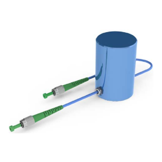
K-FS65-30-10-302 FS65 - Accelerometer • Outdoor • NC 1.1.1 Overview The FS65 - Accelerometer is a Fiber Bragg Grating (FBG) based sensor, suitable for a large range of appli cations where low frequency and small amplitude vibra tions are present. -
Page 5: Applications
Based on the measurement of an absolute parameter - the Bragg wavelength - independent of power fluctua tions. 1.1.3 Applications HBM FiberSensing accelerometer can be used in a large range of monitoring applications, including measuring ambient induced vibration of civil structures. : Civil Engineering : Energy : R&D... -
Page 6: Quality
HBM FiberSensing, S.A. concentrates all optical sensing activity of HBM and is an ISO 9001:2008 certified com pany. 1.1.5 Accessories The implementation of complex sensing networks in large structures is made simpler with HBM FiberSensing accessories. -
Page 7: General Specifications
FC/APC SC/APC NC (No Connectors) Environmental Operation temperature -20 to 80 ºC Protection class IP68 Mechanical Materials Aluminum Dimensions 73 x Ø 53 mm Weight 250 g Typical values For 1 pm resolution in wavelength measurement FS65 A4265-2.3 HBM: public... -
Page 8: Sensor Installation
Included Material Accelerometer List of Needed Equipment The needed tools to install the FS65 - Accelerometer depend on the structure the sensor is to be installed on. In many cases, mounting parts may need to be designed in order to adapt the sensor to the spot where it is going to be installed. -
Page 9: Placing The Sensor
Sensor Installation 2.1.2 Placing the Sensor The FS65 - Accelerometers can be placed headed up, headed down or towards the side (Fig. 2.1). Ó Ó Ó Ó Ó Ó Ó Ó Ó Ó Ó Ó Ó Ó Ó Ó Ô Ô Ô Ô Ô Ô Ô Ô Ô Ô Ô Ô Ô... -
Page 10: Fixing The Sensor
The Accelerometer has a M5 hole on its basis to be screwed to the surface. 2.1.4 Protecting the Sensor Accelerometer is IP68 rated, meaning that no protection is needed. Nevertheless, it can be protected with a box or other protection methods. FS65 A4265-2.3 HBM: public... -
Page 11: Bi Or Triaxial Accelerometer
- 1x Cover - 8x M6x20 List of Needed Equipment The needed tools to install the FS65 - Accelerometer depend on the structure the sensor will be installed. In many cases, mounting parts may need to be designed in order to adapt the sensor to the spot where it is going to be installed. -
Page 12: Assembling The Sensors
Its position must be set according to its measuring direc tion. On Fig. 2.3 an example of the possible two measur ing directions is presented and on Fig. 2.4 a Triaxial assembly is presented. measuring directions Fig. 2.3 measuring directions Fig. 2.4 FS65 A4265-2.3 HBM: public... - Page 13 Start by screwing the position block to the mounting plate using 3 of the provided M5x12 screws. These screws should be threaded from the backside as shown on Fig. 2.5. Mounting plate M5x12 Fig. 2.5 Position block Fig. 2.6 FS65 A4265-2.3 HBM: public...
- Page 14 Ensure that the fibers are oriented at approximately 30º, with the fibers that will be exiting the protection cover at the lower position (see Fig. 2.7 and Fig. 2.8). M5x8 Fig. 2.7 Approx. 30° Fig. 2.8 Fig. 2.9 FS65 A4265-2.3 HBM: public...
- Page 15 Sensor Installation For the vertical axis sensor, use the remaining M5x12 screw. Place the vertical sensor with the fibers oriented at 45º (Fig. 2.12). M5x12 Fig. 2.10 Fig. 2.11 45° Fig. 2.12 FS65 A4265-2.3 HBM: public...
- Page 16 (Fig. 2.14). Cable Guide M3x6 Fig. 2.13 Fig. 2.14 Considering the triaxial configuration and the defined directions as represented on Fig. 2.15, sensor connec tion should be performed as on Fig. 2.16: FS65 A4265-2.3 HBM: public...
- Page 17 Standard Accelerometers are delivered with 2 m length cables on each side. This is not an optimized length for the Bi or Triaxial configuration, but connections can be performed. Fig. 2.17 shows an assembly of sensors with FS65 A4265-2.3 HBM: public...
- Page 18 Fig. 2.19. Then, take cable A of the sensor on the z axis and place it around the assembly as on Fig. 2.20. Use an Optical Adapter and attach both connectors. FS65 A4265-2.3 HBM: public...
- Page 19 Fig. 2.21 Fig. 2.22 Proceed in a similar way with cable B of the z axis accelerometer (Fig. 2.21) and cable A of the y axis accelerometer (Fig. 2.22). Use clumps to fix cabling and connections. FS65 A4265-2.3 HBM: public...
-
Page 20: Fixing The Assembly
This means that for outdoor usage of the assembly arranged as above should have the connectors protected against moisture and dust. HBM FiberSensing suggests the use of a vul canizing tape around the connectors and adapter (Fig. 2.23). - Page 21 Sensor Installation Fig. 2.24 FS65 A4265-2.3 HBM: public...
-
Page 22: Sensor Configuration
Sensor Configuration Sensor Configuration Sensor Calibration Sheet Every HBM FiberSensing sensor is provided with a cali bration sheet. The layout of this document is the same for all accelerometers. Fig. 3.1 FS65 A4265-2.3 HBM: public... -
Page 23: General Nformation
S x is the wavelength shift in nm S S is the given sensitivity in nm/g S CWL is the central wavelength of the sensor at the zero moment in nm S WL is the measured wavelength in nm. FS65 A4265-2.3 HBM: public... - Page 24 HBM Test and Measurement Tel. +49 6151 803-0 Fax +49 6151 803-9100 info@hbm.com measure and predict with confidence...
Need help?
Do you have a question about the FS65 and is the answer not in the manual?
Questions and answers