Table of Contents
Advertisement
Quick Links
ASSEMBLY MANUAL
WWW.SEAGULLMODELS.COM
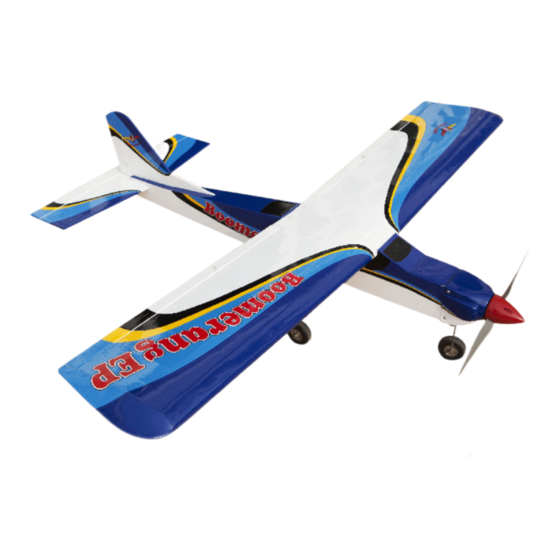
BOOMERANG EP
ARF TRAINER KIT
MS: 211
" Graphics and specifications may change without notice " .
Specifications:
Wingspan---------------56.0 in (142.2 cm).
Wing area----------------263.5sq.in (17.0 sq.dm).
Weight-------------------4.4 - 4.8 lbs (2.0 - 2.2 kg).
ALMOST
Length-------------------41.2 in (104.7cm).
READY TO FLY
Electric Power 32..............................................
Speed control 50A............................................
(APC) 11x6 EP..................................................
Radio--------------------4 channels with 4 servos.
Flying skill level intermediate/ advanced
www.seagullmodels.com
1
Advertisement
Table of Contents

Related Manuals for Seagull Models BOOMERANG EP


Summary of Contents for Seagull Models BOOMERANG EP
- Page 1 ASSEMBLY MANUAL WWW.SEAGULLMODELS.COM BOOMERANG EP ARF TRAINER KIT MS: 211 “ Graphics and specifications may change without notice “ . Specifications: Wingspan---------------56.0 in (142.2 cm). Wing area----------------263.5sq.in (17.0 sq.dm). Weight-------------------4.4 - 4.8 lbs (2.0 - 2.2 kg). ALMOST Length-------------------41.2 in (104.7cm).
-
Page 2: Additional Items Required
You will find that most of the work has been done for you already. The motor mount has been fitted and the hinges are pre-installed. Flying the BOOMERANG EP is simply a joy. This instruction manual is designed to help you build a great flying earoplane. Please read this manual throughly before starting assembly of your BOOMERANG EP. -
Page 3: Hinging The Aileron
WWW.SEAGULLMODELS.COM 4) Deflect the aileron and completely saturate HINGING THE AILERON. each hinge with thin C/A glue. The ailerons front surface should lightly contact the wing Note : The control surfaces, including the ai- during this procedure. Ideally, when the hing- lerons, elevators, and rudder, are pre- es are glued in place, a 1/64”... -
Page 4: Hinging The Rudder
BOOMERANG EP Instruction Manual. HINGING THE RUDDER. Glue the rudder hinges in place using the same techniques used to hinge the ailerons. 5) Turn the wing panel over and deflect the aileron in the opposite direction from the opposite side. Apply thin C/A glue to each hinge, making sure that the C/A pene- trates into both the aileron and wing panel. -
Page 5: Installing The Aileron Servo
WWW.SEAGULLMODELS.COM INSTALLING THE AILERON SERVO. Thread. 1) Install the rubber grommets and brass collets onto the aileron servo. Test fit the servo into the aileron servo mount. 4) Tape the servo lead to the wing to prevent it from falling back into the wing. Because the size of servos differ, you may need to adjust the size of the precut openingin the mount. -
Page 6: Aileron Linkage
BOOMERANG EP Instruction Manual. 8) Make a 90-degree bend at the mark and AILERON LINKAGE. cut off the excess wire leaving 10mm past the bend. 1) Using a ruler & pen to draw a straight line as below picture. 2) Locate the two nylon control horns, two nylon control horn backplates and four ma- chine screws. -
Page 7: Nose Gear Installation
WWW.SEAGULLMODELS.COM NOSE GEAR INSTALLATION. See below pictures. Collar. Steering arm. Thread locker glue. Pushrod wire. INSTALLING THE FUSELAGE SERVOS. M4x20mm Because the size of servos differ, you may need to adjust the size of the precut opening in the mount. The notch in the sides of the mount allow the servo lead to pass through. - Page 8 BOOMERANG EP Instruction Manual. 1) Install the rubber grommets and brass M4x30mm collets onto the throttle servo. Test fit the servo into the aileron servo mount. 2) Secure the servos with the screws provid- ed with your radio system. Elevator servo.
- Page 9 WWW.SEAGULLMODELS.COM COWLING 1) Slide the fiberglass cowl over the motor and line up the back edge of the cowl with the marks you made on the fuselage then trim and cut as shown. 3x10mm 3) Install the muffler and muffler extension onto the engine and make the cutout in the cowl for muffler clearance.
-
Page 10: Installing The Spinner
BOOMERANG EP Instruction Manual. 2) Using a modeling knife, carefully remove INSTALLING THE SPINNER. the covering from over the vertical stabilizer mounting slot in the top of the fuselage. Install the spinner backplate, propeller and spinner cone. 3) Slide the stabilizer into place in the precut slot in the rear of the fuselage. -
Page 11: Vertical Stabilizer Installation
WWW.SEAGULLMODELS.COM When cutting through the covering to remove it, cut with only enough pres- sure to only cut through the covering it- self. Cutting into the balsa structure may weaken it. 6) Using a modeling knife, carefully remove the covering that overlaps the stabilizer mounting platform sides in the fuselage. -
Page 12: Control Horn Installation
BOOMERANG EP Instruction Manual. 3) While holding the vertical stabilizer firm- Vertical ly in place, use a pen and draw a line on each Stabilizer. Horizontal 90º side of the vertical stabilizer where it meets Stabilizer. the top of the fuselage. -
Page 13: Elevator Pushrod Installation
WWW.SEAGULLMODELS.COM ELEVATOR PUSHROD Control Horn. INSTALLATION. 62mm. Mounting Screws. Mounting Plate. Elevator pushrod 3) Using a 2mm drill bit and the control horns as a guide, drill the mounting holes through the elevator halves. 4) Mount the control horns then into the mounting backplates. -
Page 14: Installing The Receiver
BOOMERANG EP Instruction Manual. INSTALLING THE RECEIVER. Wing bolt 1) Plug the five servo leads and the switch lead into the receiver. Plug the battery pack lead into the switch also. 2) Wrap the receiver and battery pack in the protective foam rubber to protect them from vibration. -
Page 15: Control Throws
WWW.SEAGULLMODELS.COM With the wing attached to the fuse- lage, all parts of the model installed ( ready to fly), and empty fuel tanks, 72 MM hold the model at the marked bal- ance point with the stabilizer level. Lift the model. If the tail drops when you lift, the model is “tail heavy”... -
Page 16: Flight Preparation
A) Plug in your radio system per the 2) Check every bolt and every glue joint manufacturer’s instructions and turn in the BOOMERANG EP to ensure that everything on. everything is tight and well bonded. B) Check the elevator first. Pull back 3) Double check the balance of the air- on the elevator stick.
Need help?
Do you have a question about the BOOMERANG EP and is the answer not in the manual?
Questions and answers