Table of Contents
Advertisement
Quick Links
Advertisement
Table of Contents

Related Manuals for KTM 125 Duke 2017


Summary of Contents for KTM 125 Duke 2017
- Page 1 OWNER'S MANUAL 2017 125 Duke Art. no. 3213561en...
- Page 3 KTM accepts no liability for delivery options, devi- ations from illustrations and descriptions, misprints, and other errors.
- Page 4 Reproduction, even in part, as well as copying of all kinds, is permitted only with the express written permission of the copyright owner. ISO 9001(12 100 6061) According to the international quality management standard ISO 9001, KTM uses quality assurance processes that lead to the maximum possible quality of the products.
-
Page 5: Table Of Contents
TABLE OF CONTENTS CONTROLS..............22 TABLE OF CONTENTS MEANS OF REPRESENTATION ........7 Clutch lever............22 Symbols used ............7 Hand brake lever..........22 Formats used............8 Throttle grip ............23 SAFETY ADVICE.............. 9 Switches on the left side of the handlebar .... 23 Use definition............ - Page 6 Quick Selector 2 display ........47 Advice on first use ..........66 7.17 Menu..............48 Running in the engine ........67 7.17.1 KTM MY RIDE (optional) ........ 48 Loading the vehicle ..........68 7.17.2 Info .............. 49 RIDING INSTRUCTIONS..........70 7.17.3 Motorcycle ............
- Page 7 TABLE OF CONTENTS 11 TUNING THE CHASSIS ..........86 13.6 Checking the free travel of foot brake lever ..110 11.1 Adjusting the spring pretension of the shock 13.7 Adjusting the free travel of the foot brake absorber ............86 lever ............
- Page 8 TABLE OF CONTENTS 16.3 Checking the coolant level ........ 146 22.5 Electrical system..........175 16.4 Draining the coolant ........148 22.6 Tires ............... 176 16.5 Filling/bleeding the cooling system ....149 22.7 Fork..............176 17 TUNING THE ENGINE..........152 22.8 Shock absorber ..........
-
Page 9: Means Of Representation
All work marked with this symbol requires specialist knowledge and technical understanding. In the interest of your own safety, have these jobs performed by an authorized KTM workshop. There, your motorcycle will be optimally cared for by specially trained experts using the specialist tools required. -
Page 10: Formats Used
MEANS OF REPRESENTATION Formats used The typographical formats used in this document are explained below. Specific name Identifies a proprietary name. Name ® Identifies a protected name. Brand™ Identifies a brand available on the open market. Underlined terms Refer to technical details of the vehicle or indicate technical terms that are explained in the glossary. -
Page 11: Safety Advice
SAFETY ADVICE Use definition KTM sport motorcycles are designed and constructed to meet the normal demands of regular road operation but not for use on race courses or offroad. Info The motorcycle is authorized for public road traffic in the homologous version only. -
Page 12: Degrees Of Risk And Symbols
SAFETY ADVICE Degrees of risk and symbols Danger Indicates a danger that will immediately and invariably lead to fatal or serious permanent injury if the appropriate measures are not taken. Warning Indicates a danger that is likely to lead to fatal or serious injury if the appropriate measures are not taken. Caution Indicates a danger that may lead to minor injuries if the appropriate measures are not taken. -
Page 13: Safe Operation
Only operate the vehicle when it is in perfect technical condition, in accordance with its intended use, and in a safe and environmentally compatible manner. An appropriate driver's license is needed to ride the vehicle on public roads. Have malfunctions that impair safety promptly eliminated by an authorized KTM workshop. Adhere to the information and warning labels on the vehicle. -
Page 14: Protective Clothing
– Always wear protective clothing that is in good condition and meets the legal regulations. In the interest of your own safety, KTM recommends that you only operate the vehicle while wearing protective clothing. Work rules Special tools are necessary for certain tasks. The tools are not contained in the vehicle but can be ordered under the number in parenthe- ses. -
Page 15: Owner's Manual
Keep the Owner's Manual in an accessible place to enable you to refer to it as needed. If you would like to know more about the vehicle or have questions on the material you read, please contact an authorized KTM dealer. -
Page 16: Important Notes
Manufacturer and implied warranty The work specified in the service schedule may only be performed in an authorized KTM workshop and must be recorded in both the Service & Warranty Booklet and in KTM Dealer.net, otherwise any warranty coverage will become void. Damage or secondary damage caused by tampering with and/or conversions on the vehicle are not covered by the warranty. -
Page 17: Service
Please follow the instructions in the text. Customer service Your authorized KTM dealer will be happy to answer any questions you may have on your vehicle and KTM. A list of authorized KTM dealers can be found on the KTM website. -
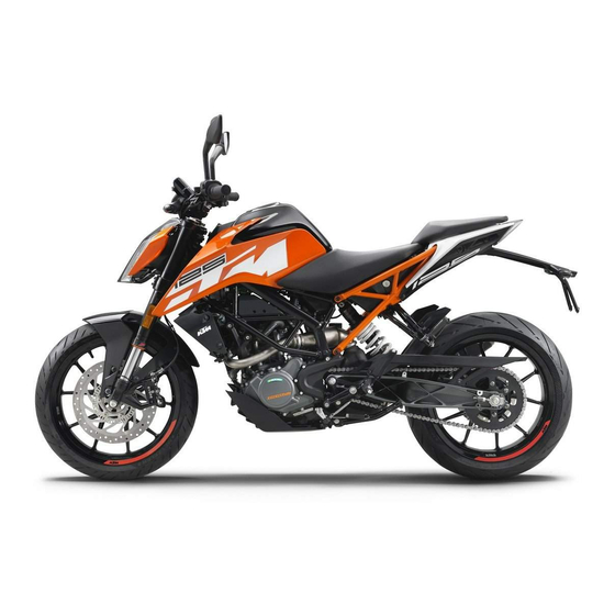
Page 18: View Of Vehicle
VIEW OF VEHICLE View of vehicle, front left (example) F00781-10... - Page 19 VIEW OF VEHICLE Combination instrument Rear mirror Clutch lever ( p. 22) Front rider's seat Seat lock ( p. 30) Passenger seat Grab handles ( p. 31) Shift lever ( p. 32) Side stand ( p. 34) Engine number ( p.
-
Page 20: View Of Vehicle, Rear Right (Example)
VIEW OF VEHICLE View of vehicle, rear right (example) F00782-10... - Page 21 VIEW OF VEHICLE Tool set ( p. 31) Light switch ( p. 24) Menu switch ( p. 24) Turn signal switch ( p. 25) Horn button ( p. 25) Filler cap Electric starter button ( p. 26) Emergency OFF switch ( p.
-
Page 22: Serial Numbers
SERIAL NUMBERS Chassis number The chassis number is stamped on the right side of the steering head. 0 0 1 402408-10 Type label The type label is on the right of the frame behind the steering head. 0 0 1 402174-10... -
Page 23: Engine Number
SERIAL NUMBERS Engine number The engine number is stamped on the left side of the engine under the engine sprocket. 402486-10 Key number The key number can be found on the KEYCODECARD. Info You need the key number to order a spare key. Keep the KEYCODECARD in a safe place. -
Page 24: Controls
CONTROLS Clutch lever The clutch lever is fitted on the left side of the handlebar. F00717-10 Hand brake lever The hand brake lever is fitted on the right side of the handlebar. The front brake is engaged using the hand brake lever. F00718-10... -
Page 25: Throttle Grip
CONTROLS Throttle grip The throttle grip is fitted on the right side of the handlebar. F00718-11 Switches on the left side of the handlebar 6.4.1 Combination switch The combination switch is fitted on the left side of the handlebar. Overview of the left combination switch Light switch ( p. -
Page 26: Light Switch
CONTROLS 6.4.2 Light switch Light switch is fitted on the left side of the handlebar. Possible states Low beam on – Light switch in position . In this position, the low beam and the tail light are switched on. High beam on – Push the light switch to position . -
Page 27: Turn Signal Switch
CONTROLS 6.4.4 Turn signal switch Turn signal switch is fitted on the left side of the handlebar. Possible states Turn signal off – Turn signal switch pushed toward the switch housing. Left turn signal, on – Turn signal switch pressed to the left. The turn signal switch returns automatically to the central position after use. -
Page 28: Switches On The Right Side Of The Handlebar
CONTROLS Switches on the right side of the handlebar 6.5.1 Emergency OFF switch The emergency OFF switch is fitted on the right side of the handlebar. Possible states Emergency OFF switch off – In this position, the ignition circuit is interrupted, a running engine stops, and a non-running engine cannot be started. -
Page 29: Ignition/Steering Lock
CONTROLS Ignition/steering lock The ignition/steering lock is in front of the upper triple clamp. Possible states Ignition off OFF – In this position, the ignition circuit is interrupted, a run- ning engine stops, and a non-running engine will not start. The ignition key can be removed. -
Page 30: Unlocking The Steering
CONTROLS Unlocking the steering – Insert the key into the ignition/handlebar lock, press in, and turn to the right. Remove the key. You can now steer the bike again. 400731-01 Opening the filler cap Danger Fire hazard Fuel is highly flammable. The fuel in the fuel tank expands when warm and can escape if overfilled. - Page 31 CONTROLS Warning Danger of poisoning Fuel is poisonous and a health hazard. – Avoid skin, eye and clothing contact with fuel. – Immediately consult a doctor if you swallow fuel. – Do not inhale fuel vapors. – In case of skin contact, rinse the affected area with plenty of water. –...
-
Page 32: Closing The Filler Cap
CONTROLS 6.10 Closing the filler cap Warning Fire hazard Fuel is highly flammable, toxic and a health hazard. – Check the filler cap is locked correctly after closing. – Change your clothing in case of fuel spills on them. – Rinse the affected area immediately with plenty of water in the event of con- tact with the skin. -
Page 33: Tool Set
CONTROLS 6.12 Tool set The tool set is located under the passenger seat. F00729-10 6.13 Grab handles The grab handles are used for moving the motorcycle around. If you carry a passenger, the passenger can hold onto the grab handles during the trip. F00741-10... -
Page 34: Passenger Footrests
CONTROLS 6.14 Passenger footrests The passenger footrests can be folded in and out. Possible states Passenger footrests folded up – For operation without a passenger. • Passenger footrests folded down – For operation with a passenger. • F00731-10 6.15 Shift lever Shift lever is mounted on the left side of the engine. -
Page 35: Foot Brake Lever
CONTROLS The gear positions can be seen in the photograph. The neutral or idle position is between the first and second gears. 401950-11 6.16 Foot brake lever Foot brake lever is located in front of the right footrest. The foot brake lever is used to activate the rear brake. 402177-10... -
Page 36: Side Stand
CONTROLS 6.17 Side stand The side stand is on the left side of the vehicle. The side stand is used to park the motorcycle. Info The side stand must be folded up during motorcycle use. Side stand is coupled with the safety start system; see the riding instructions. Possible states Side stand folded out –... -
Page 37: Combination Instrument
COMBINATION INSTRUMENT Combination instrument The combination instrument is attached in front of the handlebar. The combination instrument is divided into two function areas. indicator lamps ( p. 38) Display 402800-10 Activation and test Activation The combination instrument is activated when the ignition is switched on. Info The brightness of the displays is controlled by a brightness sensor in the combina- tion instrument. -
Page 38: Day-Night Mode
COMBINATION INSTRUMENT Day-Night mode Day mode is shown in a bright color. 402803-01 Night mode is shown in a dark color. Info The light sensor in the combination instrument measures the brightness of the envi- ronment and automatically switches the display to day or night mode. The display is brightened, darkened or switched to the other mode depending on the brightness measured by the light sensor. -
Page 39: Warning Notes
COMBINATION INSTRUMENT Warning notes Warning notes appear on the top and/or bottom edge of the display, these are marked yel- low or red depending on their relevance. Yellow warning notes indicate errors or information which requires prompt intervention or an adjustment to the riding style. Red warning notes indicate errors or information which requires immediate interven- tion. -
Page 40: Indicator Lamps
COMBINATION INSTRUMENT Indicator lamps F00900-01... - Page 41 COMBINATION INSTRUMENT The indicator lamps offer additional information about the operating state of the motorcycle. When the ignition is switched on, all indicator lamps light up briefly. Possible states The turn signal indicator lamp flashes green simultaneously with the turn signal – The turn signal is switched on. Malfunction indicator lamp lights up yellow –...
-
Page 42: Display
COMBINATION INSTRUMENT Display F00877-10... - Page 43 COMBINATION INSTRUMENT Speed ( p. 42) Shift warning light ( p. 43) The shift warning light is integrated in the tachometer display. Gear display Unit for the speed display Speed ( p. 44) Unit for the speedometer ODO display ( p.
-
Page 44: Speed
COMBINATION INSTRUMENT Speed The speed is measured in revolutions per minute. F00878-12... -
Page 45: Shift Warning Light
COMBINATION INSTRUMENT Shift warning light The shift warning light is integrated in the tachometer display. In the Shift Light menu, the engine speed for the shift warning light can be set. The shift warning light is always active during the running-in phase (up to 1,000 km / 621 mi). The shift warning light can only be deactivated, and the values for RPM1 and RPM2 can only be adjusted after this. -
Page 46: Speed
COMBINATION INSTRUMENT Speed is shown in kilometers per hour km/h or in miles per hour mph. Speed 402806-10 7.10 ODO display The total distance covered ODO is shown in area of the display. Info This value is retained, even if the battery is disconnected from the vehicle or the fuse blows. -
Page 47: Coolant Temperature Indicator
COMBINATION INSTRUMENT 7.11 Coolant temperature indicator The coolant temperature indicator consists of bars. The more bars that light up, the hotter the coolant. Info When all bars light up, the following warning note ENGINE TEMP HIGH appears. Possible states The engine is cold – Up to three bars light up. •... -
Page 48: Time
COMBINATION INSTRUMENT 7.13 Time The time is shown in area of the display. The time is displayed in 24 hour format in all languages except for EN-US. The time is dis- played in 12 hour format if the language is set to EN-US. The time can be configured in the Clock/Date menu. -
Page 49: Quick Selector 1 Display
COMBINATION INSTRUMENT 7.15 Quick Selector 1 display When the menu is closed, the Quick Selector 1 menu is opened by pressing the UP button. Press the BACK button to close Quick Selector 1. Info The Quick Selector 1 can be configured in the Quick Selector 1 menu. Any informa- tion can be selected. -
Page 50: Menu
Press the SET button when the menu is closed. – Press the UP or DOWN button until KTM MY RIDE is marked. Press the SET button to open the menu. In KTM MY RIDE a suitable cellphone can be paired with the combination instrument via Bluetooth ®... -
Page 51: Info
COMBINATION INSTRUMENT 7.17.2 Info – Press the SET button when the menu is closed. – Press the UP or DOWN button until Info is marked. Press the SET button to open the menu. General information can be accessed in Info. F00804-02 7.17.3 Motorcycle... -
Page 52: Settings
COMBINATION INSTRUMENT 7.17.4 Settings Condition • The motorcycle is stationary. – Press the SET button when the menu is closed. – Press the UP or DOWN button until Settings is marked. Press the SET button to open the menu. Favorites and quick selection can be configured in Settings. F00804-04 7.17.5 Preferences... -
Page 53: Pairing (Optional)
– Press the SET button when the menu is closed. – Press the UP or DOWN button until KTM MY RIDE is marked. Press the SET button to open the menu. – Press the UP or DOWN button until Pairing is marked. Press the SET button to open the F00842-01 menu. -
Page 54: Audio (Optional)
– Press the SET button when the menu is closed. – Press the UP or DOWN button until KTM MY RIDE is marked. Press the SET button to open the menu. Warning F00837-01 Danger of accidents Headphone volume which is too high distracts attention... -
Page 55: Telephony (Optional)
COMBINATION INSTRUMENT 7.17.8 Telephony (optional) Condition • Function KTM MY RIDE activated (optional). • Function Bluetooth ® activated. The Bluetooth • ® function should also be activated in the device to be paired. • Headset linked with appropriate cellphone. Warning Danger of accidents Headphone volume which is too high distracts attention... -
Page 56: General Info
COMBINATION INSTRUMENT 7.17.9 General Info – Press the SET button when the menu is closed. – Press the UP or DOWN button until Info is marked. Press the SET button to open the menu. – Press the UP or DOWN button until General Info is marked. Press the SET button to open the menu. -
Page 57: Trip 2
COMBINATION INSTRUMENT 7.17.11 Trip 2 – Press the SET button when the menu is closed. – Press the UP or DOWN button until Info is marked. Press the SET button to open the menu. – Press the UP or DOWN button until Trip 2 is marked. Press the SET button to open the menu. -
Page 58: 7.17.13 Abs
COMBINATION INSTRUMENT 7.17.13 ABS Condition • The motorcycle is stationary. – Press the SET button when the menu is closed. – Press the UP or DOWN button until Motorcycle is marked. Press the SET button to open the menu. Warning Voiding of the government approval for road use and the insurance coverage If the ABS is switched off completely, the vehicle's approval for road use is invali- dated. -
Page 59: 7.17.14 Favourites
COMBINATION INSTRUMENT 7.17.14 Favourites Condition • The motorcycle is stationary. – Press the SET button when the menu is closed. – Press the UP or DOWN button until Settings is marked. Press the SET button to open the menu. – Press the UP or DOWN button until Favourites is marked. -
Page 60: Quick Selector 2
COMBINATION INSTRUMENT 7.17.16 Quick Selector 2 Condition • The motorcycle is stationary. – Press the SET button when the menu is closed. – Press the UP or DOWN button until Settings is marked. Press the SET button to open the menu. -
Page 61: 7.17.18 Shift Light
COMBINATION INSTRUMENT Info The Bluetooth ® function can only be used in conjunction with KTM MY RIDE (optional). When the Bluetooth ® function is switched on, the Bluetooth ® symbol appears in the display of the combination instrument. 7.17.18 Shift Light Condition •... -
Page 62: 7.17.19 Setting The Time And Date
COMBINATION INSTRUMENT 7.17.19 Setting the time and date Condition The motorcycle is stationary. – Press the SET button when the menu is closed. – Press the UP or DOWN button until Preferences appears. Press the SET button to open the menu. –... -
Page 63: 7.17.20 Drl
COMBINATION INSTRUMENT Setting the date – Press the UP or DOWN button until the date is marked. – Press the SET button. The day flashes and is underlined. – Press the UP or DOWN button until the current day is set. –... -
Page 64: 7.17.21 Distance
COMBINATION INSTRUMENT Warning Danger of accidents When visibility is poor, the daytime running light is not a substitute for the low beam. Automatic switching between the daytime running light and low beam may only be partially available when visibility is significantly impaired due to fog, snow or rain. -
Page 65: 7.17.22 Temp
COMBINATION INSTRUMENT – Activate the menu item using the UP or DOWN button. – Press the SET button to confirm the desired unit. 7.17.22 Temp Condition • The motorcycle is stationary. – Press the SET button when the menu is closed. –... -
Page 66: 7.17.24 Language
COMBINATION INSTRUMENT – Press the SET button to confirm the desired unit. 7.17.24 Language Condition • The motorcycle is stationary. – Press the SET button when the menu is closed. – Press the UP or DOWN button until Preferences is marked. Press the SET button to open the menu. -
Page 67: 7.17.26 Extra Functions
Use the UP or DOWN button to navigate through the extra functions. F00831-01 The optional extra functions are listed in Extra Functions. Info The current KTM PowerParts and the available software for your vehicle can be found on the KTM website. -
Page 68: Preparing For Use
Warning Danger of accidents Non-approved or non-recommended tires and wheels impact the handling characteristic. – Only use tires/wheels approved by KTM with the corresponding speed index. Warning Danger of accidents New tires have reduced road grip. The contact surface on new tires is not yet roughened. -
Page 69: Running In The Engine
When using your vehicle, remember that others may feel disturbed by excessive noise. – Make sure that the pre-delivery inspection work has been carried out by an authorized KTM workshop. You receive a delivery certificate and the Service and Warranty Booklet at vehicle handover. -
Page 70: Loading The Vehicle
PREPARING FOR USE Loading the vehicle Warning Danger of accidents Total weight and axle loads influence the handling characteristic. The overall weight consists of: motorcycle ready for operation and with a full tank, driver and passenger with protective clothing and helmet, and luggage. –... - Page 71 PREPARING FOR USE – If you carry any baggage, make sure it is fixed firmly as close as possible to the center of the vehicle and ensure even weight distribu- tion between the front and rear wheels. – Do not exceed the overall maximum permitted weight and the axle loads. Guideline Maximum permissible overall weight 355 kg (783 lb.)
-
Page 72: Riding Instructions
RIDING INSTRUCTIONS Checks and maintenance when preparing for use Info Before every trip, check the condition of the vehicle and ensure that it is roadworthy. The vehicle must be in perfect technical condition when used. – Check the engine oil level. ( p. -
Page 73: Starting
RIDING INSTRUCTIONS Starting Danger Danger of poisoning Exhaust gases are toxic and inhaling them may result in unconsciousness and death. – Always make sure there is sufficient ventilation when running the engine. – Use an effective exhaust extraction system when starting or running the engine in an enclosed space. Caution Danger of accidents Electronic components and safety devices will be damaged if the battery is discharged or missing. - Page 74 RIDING INSTRUCTIONS – Unlock the steering. ( p. 28) – Sit on the vehicle, take the weight off of the side stand, and move up all the way. – Turn the emergency OFF switch to the position – Switch on the ignition by turning the ignition key to the position After you switch on the ignition, you can hear the fuel pump working for about two seconds.
-
Page 75: Starting Off
RIDING INSTRUCTIONS Starting off – Pull the clutch lever, engage 1st gear, release the clutch lever slowly, and simultaneously open the throttle carefully. If the engine dies while starting off, only pull the clutch lever and press the electric starter button. You do not need to shift into neutral. - Page 76 RIDING INSTRUCTIONS Warning Risk of injury The passenger may fall from the motorcycle if they conduct themselves incorrectly. – Ensure that the passenger sits correctly on the passenger seat, places his or her feet on the passenger foot rest and holds on to the rider or the grab handles.
- Page 77 Check and, if necessary, correct the coolant level on the cooling system while it is in a cooled state. Info If you hear unusual noises while riding, stop immediately, switch off the engine and contact an authorized KTM workshop. –...
-
Page 78: Applying The Brakes
You do not have to shift into neutral. – If the oil pressure warning lamp lights up during a trip, stop immediately and switch off the engine. Contact an authorized KTM workshop. – If the malfunction indicator lamp lights up during a trip, please contact an autho- rized KTM workshop as soon as possible. - Page 79 Danger of accidents A spongy pressure point on the front or rear brake reduces braking efficiency. – Check the brake system and do not continue riding until the problem is eliminated. (Your authorized KTM workshop will be glad to help.) Warning Danger of accidents The brake system fails in the event of overheating.
-
Page 80: Stopping, Parking
RIDING INSTRUCTIONS Info When the ABS is enabled, you can achieve maximum braking power even on low grip surfaces such as sandy, wet, or slippery terrain without locking of the wheels. Warning Danger of accidents The rear wheel can lock due to the engine braking effect. –... - Page 81 RIDING INSTRUCTIONS Note Material damage The vehicle may be damaged by incorrect procedure when parking. Significant damage may be caused if the vehicle rolls away or falls over. The components for parking the vehicle are designed only for the weight of the vehicle. –...
-
Page 82: Transport
RIDING INSTRUCTIONS Transport Note Danger of damage The parked vehicle can roll away or fall over. – Park the vehicle on a firm and level surface. Note Fire hazard Hot vehicle components pose a fire hazard and explosion risk. – Do not park the vehicle near to materials which are highly flammable or explosive. –... -
Page 83: Refueling
In some countries and regions, the available fuel quality and cleanliness may not be sufficient. This will result in problems with the fuel system. – Refuel only with clean fuel that meets the specified standards. (Your authorized KTM workshop will be glad to help.) - Page 84 RIDING INSTRUCTIONS Warning Environmental hazard Improper handling of fuel is a danger to the environment. – Do not allow fuel to enter the groundwater, the soil, or the sewage system. – Switch off the engine. – Open the filler cap. ( p.
-
Page 85: Service Schedule
15,000 km (9,300 mi) every 7,500 km (4,650 mi) after 1,000 km (620 mi) ○ ● ● ● ● Read out the fault memory using the KTM diagnostics tool. ○ ● ● ● ● Check that the electrical system is functioning properly. ○... - Page 86 Read out the error memory after the test ride using the KTM diagnostics tool. ○ ● ● ● ● Reset the service interval display. ○ ● ● ● ● Make the service entry in the KTM Dealer.net and in the Service and Warranty Booklet. ○ One-time interval ● Periodic interval...
-
Page 87: Recommended Work
SERVICE SCHEDULE 10.3 Recommended work Every four years Every year every 30,000 km (18,600 mi) every 7,500 km (4,650 mi) after 1,000 km (620 mi) ● Check the frame. ● Check the swingarm. ● ● Check the swingarm bearing. ● ●... -
Page 88: Tuning The Chassis
TUNING THE CHASSIS 11.1 Adjusting the spring pretension of the shock absorber Warning Danger of accidents Modifications to the suspension settings can seriously alter the vehicle's ride behavior. – Following modifications, ride slowly at first to get the feel of the new ride behavior. Info The spring pretension defines the initial status of the spring operation on the shock absorber. -
Page 89: Adjusting The Shift Lever
TUNING THE CHASSIS 11.2 Adjusting the shift lever Info The adjustment range of the shift lever is limited. – Loosen nuts – Adjust the shift lever by turning shift rod Guideline 90… 102 mm (3.54… 4.02 in) Shift rod adjustment range Info Make the same adjustments on both sides. -
Page 90: Service Work On The Chassis
SERVICE WORK ON THE CHASSIS 12.1 Raising the motorcycle with the rear lifting gear Note Danger of damage The parked vehicle can roll away or fall over. – Park the vehicle on a firm and level surface. – Mount the supports of the lifting gear. –... -
Page 91: Lifting The Motorcycle With The Front Lifting Gear
SERVICE WORK ON THE CHASSIS – Secure the motorcycle against falling over. – Remove the rear lifting gear and lean the vehicle on side stand – Remove bushings kit. 402029-10 12.3 Lifting the motorcycle with the front lifting gear Note Danger of damage The parked vehicle can roll away or fall over. -
Page 92: Taking The Motorcycle From The Front Lifting Gear
SERVICE WORK ON THE CHASSIS – Move the handlebar to the straight-ahead position. Position the lifting gear. Mounting pin (69329965030) Lifting gear, front (69329965000) Info Always raise the motorcycle at the rear first. – Raise the motorcycle at the front. 402345-01 12.4 Taking the motorcycle from the front lifting gear... -
Page 93: Cleaning The Dust Boots Of The Fork Legs
SERVICE WORK ON THE CHASSIS – Mount protection cap F00735-10 Finishing work – Remove the rear of the motorcycle from the lifting gear. ( p. 88) 12.5 Cleaning the dust boots of the fork legs Preparatory work – Raise the motorcycle with the rear lifting gear. ( p. -
Page 94: Removing The Passenger Seat
SERVICE WORK ON THE CHASSIS Warning Danger of accidents Oil or grease on the brake discs reduces the braking effect. – Always keep the brake discs free of oil and grease. – Clean the brake discs with brake cleaner when necessary. –... -
Page 95: Mounting The Passenger Seat
SERVICE WORK ON THE CHASSIS 12.7 Mounting the passenger seat – Attach hooks on the passenger seat to seat mounting on the subframe, and lower it at the rear while pushing forward. – Press down the passenger seat until it clicks into place. Warning Danger of accidents The passenger seat can come loose from the anchoring if it is not mounted correctly. -
Page 96: Mounting The Front Rider's Seat
SERVICE WORK ON THE CHASSIS 12.9 Mounting the front rider's seat Main work – Attach the front rider's seat in area and lower at the rear. – Finally, check that the driver's seat is correctly mounted. H01994-01 Finishing work – Mount the passenger seat. -
Page 97: Cleaning The Chain
SERVICE WORK ON THE CHASSIS 12.11 Cleaning the chain Warning Danger of accidents Oil or grease on the tires reduces the road grip. – Remove the lubricant from the tires using a suitable cleaning agent. Warning Danger of accidents Oil or grease on the brake discs reduces the braking effect. –... -
Page 98: Checking The Chain Tension
SERVICE WORK ON THE CHASSIS Main work – Clean the chain regularly. – Rinse off loose dirt with a soft jet of water. – Remove old grease remains with chain cleaner. Chain cleaner ( p. 188) – After drying, apply chain spray. Chain lube for road use ( p. -
Page 99: Adjusting The Chain Tension
SERVICE WORK ON THE CHASSIS Main work – Shift gear to neutral. – In the area of the chain sliding guard, press the chain upward toward the swingarm and determine chain tension Info The upper part of chain must be taut. Chain wear is not always even, so you should repeat this measurement at differ- ent chain positions. - Page 100 SERVICE WORK ON THE CHASSIS – Check the chain tension. ( p. 96) Main work – Loosen nut – Loosen nuts – Adjust the chain tension by turning adjusting screws left and right. Guideline Chain tension 5… 7 mm (0.2… 0.28 in) Turn the adjusting screws on the left and right so that the markings on the left and right chain adjusters...
-
Page 101: Checking The Chain, Rear Sprocket, And Engine Sprocket
SERVICE WORK ON THE CHASSIS 12.14 Checking the chain, rear sprocket, and engine sprocket Preparatory work – Raise the motorcycle with the rear lifting gear. ( p. 88) Main work – Check the rear sprocket and engine sprocket for wear. »... - Page 102 SERVICE WORK ON THE CHASSIS – Shift gear to neutral. – Pull the lower chain section with specified weight Guideline Weight, chain wear measurement 15 kg (33 lb.) – Measure distance of 20 chain rollers in the lower chain section. Info Chain wear is not always even, so you should repeat this measurement at differ- 0 0 A...
- Page 103 SERVICE WORK ON THE CHASSIS – Check the chain sliding guard for wear. » If in area by the chain sliding guard screw is visible from above: – Change the chain sliding guard. – Check that the chain sliding guard is firmly seated. »...
-
Page 104: Removing The Front Spoiler
SERVICE WORK ON THE CHASSIS 12.15 Removing the front spoiler – Remove screws F00740-10 – Remove screws – Take off the front spoiler. F00739-10... -
Page 105: Fitting Front Spoiler
SERVICE WORK ON THE CHASSIS 12.16 Fitting front spoiler – Position the front spoiler. Mount screws but do not tighten yet. F00740-10 – Mount and tighten screws Guideline Screw, front spoiler rear M6x9 9 Nm (6.6 lbf ft) – Tighten screws Guideline Screw, front spoiler front M6x13... -
Page 106: Brake System
– Only use spare parts on the brake system which have been approved and recom- mended by KTM. – Only use tires/wheels approved by KTM with the corresponding speed index. – Maintain the specified tire air pressure. – Service work and repairs must be performed professionally. (Your authorized KTM workshop will be glad to help.) -
Page 107: Checking The Brake Discs
The ABS indicator lamp goes out when you start off. 13.2 Checking the brake discs Warning Danger of accidents Worn-out brake discs reduce the braking effect. – Make sure that worn-out brake discs are replaced immediately. (Your authorized KTM workshop will be glad to help.) -
Page 108: Checking The Brake Fluid Level Of The Front Brake
If the brake fluid level drops below the MIN marking, the brake system is leaking or the brake linings are worn down. – Check the brake system and do not continue riding until the problem is eliminated. (Your authorized KTM workshop will be glad to help.) -
Page 109: Adding Front Brake Fluid
If the brake fluid level drops below the MIN marking, the brake system is leaking or the brake linings are worn down. – Check the brake system and do not continue riding until the problem is eliminated. (Your authorized KTM workshop will be glad to help.) - Page 110 Danger of accidents Old brake fluid reduces the braking effect. – Make sure that brake fluid for the front and rear brake is changed in accordance with the service schedule. (Your authorized KTM workshop will be glad to help.) Warning Environmental hazard Hazardous substances cause environmental damage.
-
Page 111: Checking The Front Brake Linings
Warning Danger of accidents Worn-out brake linings reduce the braking effect. – Ensure that worn-out brake linings are replaced immediately. (Your authorized KTM workshop will be glad to help.) Warning Danger of accidents Damaged brake discs reduce the braking effect. If the brake linings are not changed in time, the brake lining carriers grind against the brake disc. As a consequence, the braking effect is greatly reduced and the brake discs are destroyed. -
Page 112: Checking The Free Travel Of Foot Brake Lever
BRAKE SYSTEM – Check the brake linings for minimum thickness ≥ 1 mm (≥ 0.04 in) Minimum thickness » If the minimum thickness is less than specified: – Change the front brake linings. – Check the brake linings for damage and cracking. »... -
Page 113: Adjusting The Free Travel Of The Foot Brake Lever
BRAKE SYSTEM – Disconnect spring – Move the foot brake lever back and forth between the end stop and the contact to the foot brake cylinder piston and check free travel Guideline Free travel at foot brake lever 3… 5 mm (0.12… 0.2 in) »... -
Page 114: Checking The Rear Brake Fluid Level
If the brake fluid level drops below the MIN marking, the brake system is leaking or the brake linings are worn down. – Check the brake system and do not continue riding until the problem is eliminated. (Your authorized KTM workshop will be glad to help.) -
Page 115: Adding Rear Brake Fluid
If the brake fluid level drops below the MIN marking, the brake system is leaking or the brake linings are worn down. – Check the brake system and do not continue riding until the problem is eliminated. (Your authorized KTM workshop will be glad to help.) - Page 116 Danger of accidents Old brake fluid reduces the braking effect. – Make sure that brake fluid for the front and rear brake is changed in accordance with the service schedule. (Your authorized KTM workshop will be glad to help.) Warning Environmental hazard Hazardous substances cause environmental damage.
- Page 117 BRAKE SYSTEM Condition The screw cap is locked. – Remove screw and take off the screw cap lock. H01142-10 – Stand the vehicle upright. – Remove screw cap with membrane – Add brake fluid to level Brake fluid DOT 4 / DOT 5.1 ( p.
-
Page 118: Checking The Brake Linings Of The Rear Brake
Warning Danger of accidents Worn-out brake linings reduce the braking effect. – Ensure that worn-out brake linings are replaced immediately. (Your authorized KTM workshop will be glad to help.) Warning Danger of accidents Damaged brake discs reduce the braking effect. If the brake linings are not changed in time, the brake lining carriers grind against the brake disc. As a consequence, the braking effect is greatly reduced and the brake discs are destroyed. -
Page 119: Wheels, Tires
WHEELS, TIRES 14.1 Removing the front wheel Preparatory work – Raise the motorcycle with the rear lifting gear. ( p. 88) – Lift the motorcycle with the front lifting gear. ( p. 89) Main work – Remove screws with washers and push the fender slightly to the side. –... -
Page 120: Installing The Front Wheel
WHEELS, TIRES 14.2 Installing the front wheel Warning Danger of accidents Oil or grease on the brake discs reduces the braking effect. – Always keep the brake discs free of oil and grease. – Clean the brake discs with brake cleaner when necessary. –... - Page 121 WHEELS, TIRES – Clean the thread of the wheel spindle and screw – Clean and grease wheel spindle. Long-life grease ( p. 188) – Position the front wheel and insert the wheel spindle. The brake linings are correctly positioned. – Mount and tighten screw Guideline Screw, front wheel spindle...
-
Page 122: Removing The Rear Wheel
WHEELS, TIRES Guideline Screw, fork stub 15 Nm (11.1 lbf ft) 14.3 Removing the rear wheel Preparatory work – Raise the motorcycle with the rear lifting gear. ( p. 88) Main work – Remove screw F00776-10... -
Page 123: Installing The Rear Wheel
WHEELS, TIRES – Remove screw and pull wheel speed sensor out of the hole. – Remove nut and washer. – Remove chain adjuster – Holding the rear wheel, withdraw wheel spindle with the washer and chain adjuster – Push the rear wheel forward as far as possible and take the chain off the rear sprocket. –... - Page 124 WHEELS, TIRES Warning Danger of accidents There is no braking effect to start with at the rear brake after installing the rear wheel. – Actuate the foot brake several times before going on a ride until you can feel a firm pressure point. Main work –...
- Page 125 WHEELS, TIRES – Pull the rear wheel back and mount wheel spindle with the washer and chain adjuster Guideline Mount left and right chain adjusters in the same position. – Mount nut and washer. – Push the rear wheel forward so that the chain adjusters are in contact with the screws, and tighten nut Guideline In order for the rear wheel to be correctly aligned, the markings on the left and right...
-
Page 126: Checking The Rear Hub Rubber Dampers
WHEELS, TIRES Finishing work – Remove the rear of the motorcycle from the lifting gear. ( p. 88) – Check the chain tension. ( p. 96) 14.5 Checking the rear hub rubber dampers Info The engine power is transmitted from the rear sprocket to the rear wheel via 6 rubber dampers. They eventually wear out during operation. -
Page 127: Checking The Tire Condition
Danger of accidents If a tire bursts while riding, the vehicle becomes uncontrollable. – Ensure that damaged or worn tires are replaced immediately. (Your authorized KTM workshop will be glad to help.) Warning Danger of crashing Different tire tread patterns on the front and rear wheel impair the handling characteristic. - Page 128 Danger of accidents Non-approved or non-recommended tires and wheels impact the handling characteristic. – Only use tires/wheels approved by KTM with the corresponding speed index. Info The type, condition, and air pressure of the tires all have a major impact on the handling characteristics of the motorcycle.
-
Page 129: Checking The Tire Air Pressure
DOT number. The first two digits indicate the week of manufacture and the last two digits the year of manufacture. KTM recommends that the tires be changed after 5 years at the latest, regard- less of the actual state of wear. - Page 130 WHEELS, TIRES – Correct the tire air pressure. – Mount the dust cap.
-
Page 131: Electrical System
ELECTRICAL SYSTEM 15.1 Daytime running light (DRL) Warning Danger of accidents When visibility is poor, the daytime running light is not a sub- stitute for the low beam. Automatic switching between the daytime running light and low beam may only be partially available when visibility is significantly impaired due to fog, snow or rain. -
Page 132: Removing The Battery
ELECTRICAL SYSTEM 15.2 Removing the battery Warning Risk of injury Battery acid and battery gases cause serious chemical burns. – Keep batteries out of the reach of children. – Wear suitable protective clothing and safety glasses. – Avoid contact with battery acid and battery gases. –... -
Page 133: Installing The Battery
ELECTRICAL SYSTEM – Pull back positive terminal cover – Disconnect positive cable from the battery. – Detach rubber band – Pull the battery up and out of the battery holder. Info Never operate the motorcycle with a discharged battery or without a battery. In both cases, electrical components and safety devices can be damaged. -
Page 134: Recharging The Battery
ELECTRICAL SYSTEM – Position negative cable ; mount and tighten the screw. F00774-11 Finishing work – Mount the front rider's seat. ( p. 94) – Mount the passenger seat. ( p. 93) – Set the time and date. ( p. 60) 15.4 Recharging the battery Warning... - Page 135 ELECTRICAL SYSTEM Warning Environmental hazard Batteries contain environmentally-hazardous materials. – Do not dispose of batteries as household waste. – Dispose of batteries at a collection point for used batteries. Info Even when there is no load on the battery, it discharges steadily. The charging level and the method of charging are very important for the service life of the battery.
- Page 136 ELECTRICAL SYSTEM Main work – Connect the battery charger to the battery. Switch on the battery charger. Battery charger (58429074000) You can also use the battery charger to test rest potential and start potential of the bat- tery, and to test the alternator. With this device, you cannot overcharge the battery. Info Never remove lid Charge the battery with a maximum of 10% of the capacity specified on battery...
-
Page 137: Changing The Abs Fuses
ELECTRICAL SYSTEM 15.5 Changing the ABS fuses Warning Fire hazard Incorrect fuses overload the electrical system. – Only use fuses with the required ampere value. – Do not bypass or repair fuses. Info Two fuses for the ABS are located under the passenger seat. These fuses protect the return pump and the hydraulic unit of the ABS. -
Page 138: Changing The Fuses Of Individual Power Consumers
ELECTRICAL SYSTEM Replace spare fuse in the fuse box so that it is available if needed. – Mount the protection cap. To change the fuse of the ABS return pump: – Take off the protection cap and remove fuse Warning Fire hazard Incorrect fuses overload the electrical system. - Page 139 ELECTRICAL SYSTEM Preparatory work – Switch off all power consumers and switch off the engine. – Remove the passenger seat. ( p. 92) Main work – Open fuse box cover – Remove the defective fuse. Guideline Fuse 1 - 30 A - main fuse Fuse 2 - 10 A - combination instrument Fuse 3 - 10 A - power relay Fuse 4 - 15 A - ignition coil, fuel pump, start auxiliary relay, horn...
- Page 140 ELECTRICAL SYSTEM Warning Fire hazard Incorrect fuses overload the electrical system. – Only use fuses with the required ampere value. – Do not bypass or repair fuses. – Use spare fuses with the correct rating only. Fuse (75011088010) ( p. 175) Fuse (75011088015) ( p.
-
Page 141: Checking The Headlight Setting
ELECTRICAL SYSTEM 15.7 Checking the headlight setting – Position the vehicle upright on a horizontal surface in front of a light wall and make a mark at the height of the center of the low beam headlight. 0 0 A –... - Page 142 ELECTRICAL SYSTEM Main work – Turn adjusting screw to adjust the headlight range. Info Turn clockwise to increase the headlight range; turn counterclockwise to reduce the headlight range. If you have a payload, you may have to correct the headlight range. Screw also secures the headlight.
-
Page 143: Diagnostics Connector
ELECTRICAL SYSTEM 15.9 Diagnostics connector Diagnostics connector is located under the passenger seat. H01906-10 15.10 USB diagnostics plug The USB diagnostics plug is located under the combination instrument. Info The USB diagnostics plug is intended for diagnostics purposes only and is not suit- able for supplying power to external devices. -
Page 144: Cooling System
COOLING SYSTEM 16.1 Cooling system Water pump in the engine ensures forced circulation of the coolant. The pressure resulting from the warming of the cooling system is regulated by a valve in radiator cap . Heat expansion causes excess coolant to flow into compensating tank When the temperature falls, this surplus coolant is sucked back into the cooling system. - Page 145 COOLING SYSTEM The coolant is cooled by the air stream and a radiator fan , which is controlled by a ther- moswitch. The lower the speed, the less the cooling effect. Dirty cooling fins also reduce the cooling effect. H01904-10...
-
Page 146: Checking The Antifreeze And Coolant Level
COOLING SYSTEM 16.2 Checking the antifreeze and coolant level Warning Danger of scalding During motorcycle operation, the coolant gets very hot and is under pressure. – Do not open the radiator, the radiator hoses or other cooling system components if the engine or the cooling system are at oper- ating temperature. - Page 147 COOLING SYSTEM – Stand the motorcycle upright on a horizontal surface. – Remove cap of the compensating tank. – Check the antifreeze in the coolant. −25… −45 °C (−13… −49 °F) » If the antifreeze in the coolant does not match the specified value: –...
-
Page 148: Checking The Coolant Level
COOLING SYSTEM » If you had to add more coolant than the specified amount: > 0.20 l (> 0.21 qt.) – Fill/bleed the cooling system. p. 149) – Mount the radiator cap. 16.3 Checking the coolant level Warning Danger of scalding During motorcycle operation, the coolant gets very hot and is under pressure. –... - Page 149 COOLING SYSTEM – Stand the motorcycle upright on a horizontal surface. – Check the coolant level in compensating tank The coolant level must be between the two markings. » If the coolant level does not match the specified value: – Correct the coolant level.
-
Page 150: Draining The Coolant
COOLING SYSTEM 16.4 Draining the coolant Warning Danger of scalding During motorcycle operation, the coolant gets very hot and is under pressure. – Do not open the radiator, the radiator hoses or other cooling system components if the engine or the cooling system are at oper- ating temperature. -
Page 151: Filling/Bleeding The Cooling System
COOLING SYSTEM Main work – Position the motorcycle upright. – Place a suitable container under the engine. – Remove screw – Remove the radiator cap. – Completely drain the coolant. – Mount and tighten screw with a new seal ring. Guideline F00765-10 Screw plug, water pump drain hole... - Page 152 COOLING SYSTEM Main work – Remove radiator cap F00763-11 – Loosen bleeder screw Guideline 3 turns – Tilt the vehicle slightly to the right. – Pour in coolant until it emerges without bubbles at the bleeder screw, and then mount and tighten the bleeder screw immediately.
- Page 153 COOLING SYSTEM – Start the engine and let it warm up. – Stop the engine and allow it to cool down. – When the engine is cool, check the coolant level in the radiator and, if necessary, add coolant. – Remove cap of the compensating tank and top up the coolant level to the upper marking.
-
Page 154: Tuning The Engine
TUNING THE ENGINE 17.1 Checking the play in the throttle cable – Check the throttle grip for smooth operation. – Move the handlebar to the straight-ahead position. Turn the throttle grip back and forth slightly and determine the play in throttle cable 3…... -
Page 155: Adjusting The Play In The Throttle Cable
TUNING THE ENGINE 17.2 Adjusting the play in the throttle cable – Move the handlebar to the straight-ahead position. – Push back sleeve – Loosen lock nut – Adjust the play in the throttle cable by turning adjusting screw Guideline Throttle cable play 3…... - Page 156 TUNING THE ENGINE – Check the clutch lever for smooth operation. – Move the handlebar to the straight-ahead position. – Pull the clutch lever until resistance is perceptible, and determine the play in the clutch lever 1… 3 mm (0.04… 0.12 in) Clutch lever play »...
-
Page 157: Adjusting Play In The Clutch Lever
TUNING THE ENGINE 17.4 Adjusting play in the clutch lever – Move the handlebar to the straight-ahead position. – Push back sleeve – Loosen lock nut – Adjust the play in the clutch level by turning adjusting screw Guideline 1… 3 mm (0.04… 0.12 in) Clutch lever play –... -
Page 158: Service Work On The Engine
SERVICE WORK ON THE ENGINE 18.1 Checking the engine oil level Condition The engine is at operating temperature. Preparatory work – Stand the motorcycle upright on a horizontal surface. Main work – Check the engine oil level. Info After switching off the engine, wait one minute before checking the level. The engine oil must be between the markings »... - Page 159 SERVICE WORK ON THE ENGINE Warning Environmental hazard Hazardous substances cause environmental damage. – Dispose of oils, grease, filters, fuel, cleaning agents, brake fluid, etc., correctly and in compliance with the applicable regula- tions. Info Drain the engine oil only when the engine is warm. Preparatory work –...
- Page 160 SERVICE WORK ON THE ENGINE – Remove screws . Remove oil filter cover with the O-ring. – Pull oil filter out of the oil filter housing. – Completely drain the engine oil. – Thoroughly clean the parts and sealing surface. F00770-10 –...
-
Page 161: Adding Engine Oil
SERVICE WORK ON THE ENGINE – Remove filler plug and the O-ring from the clutch cover, and fill up with engine oil. Engine oil 1.5 l (1.6 qt.) External temper- Engine oil ature: 0… 50 °C (SAE 15W/50) (32… 122 °F) p. - Page 162 SERVICE WORK ON THE ENGINE Main work – Remove filler plug and the O-ring from the clutch cover, and fill up with engine oil. 0 0 1 Engine oil (SAE 15W/50) ( p. 186) Engine oil (SAE 10W/40) ( p. 186) Info In order to achieve optimal engine performance, it is not advisable to mix differ- ent engine oils.
-
Page 163: Cleaning, Care
CLEANING, CARE 19.1 Cleaning the motorcycle Note Material damage Components become damaged or destroyed if a pressure cleaner is used incorrectly. The high pressure forces water into the electrical components, connectors, throttle cables, and bearings, etc. Pressure which is too high causes malfunctions and destroys components. –... - Page 164 CLEANING, CARE – Seal the exhaust system to keep water out. – First remove coarse dirt particles with a gentle spray of water. – Spray very dirty areas with a normal motorcycle cleaner and then clean with a paint- brush. Motorcycle cleaner ( p.
-
Page 165: Checks And Maintenance Steps For Winter Operation
CLEANING, CARE – Clean the chain. ( p. 95) – Treat bare metal parts (except for brake discs and exhaust system) with anti-corrosion materials. Preserving materials for paints, metal and rubber ( p. 189) – Treat all painted parts with a mild paint polish. Perfect Finish and high gloss polish for paints ( p. - Page 166 CLEANING, CARE – Clean the motorcycle. ( p. 161) – Clean the brakes. Info After EVERY trip on salted roads, thoroughly wash the brake calipers and brake linings with cold water and dry carefully. This should be done after the parts are cooled down and while they are installed.
-
Page 167: Storage
0… 35 °C (32… 95 °F) direct sunlight – Store the vehicle in a dry location that is not subject to large fluctuations in tempera- ture. Info KTM recommends jacking up the motorcycle. – Raise the motorcycle with the rear lifting gear. ( p. 88) -
Page 168: Preparing For Use After Storage
STORAGE – Lift the motorcycle with the front lifting gear. ( p. 89) – Cover the motorcycle with a tarp or similar cover that is permeable to air. Info Do not use non-porous materials since they prevent humidity from escaping, thus causing corrosion. -
Page 169: Troubleshooting
Operating error Carry out the start procedure. ( p. 71) – Fault in fuel injection system Read out the fault memory using the KTM diag- nostics tool. – Engine has too little power Air filter is very dirty Change the air filter. - Page 170 TROUBLESHOOTING Faults Possible cause Action – Malfunction indicator lamp lights up Fault in fuel injection system Read out the fault memory using the KTM diag- yellow nostics tool. – Engine dies during the trip Lack of fuel Refuel. ( p. 81) –...
- Page 171 TROUBLESHOOTING Faults Possible cause Action – The combination instrument shows Fuse 2 is blown Change the fuses of individual power consumers. nothing on the display p. 136) – Speedometer in combination instru- Speedometer wiring harness is dam- Check the wiring harness and plug-in connector. ment not functioning aged or plug-in connector is oxidized...
-
Page 172: Technical Data
TECHNICAL DATA 22.1 Engine Design 1-cylinder 4-stroke engine, water-cooled Displacement 125 cm³ (7.63 cu in) Stroke 47.2 mm (1.858 in) Bore 58 mm (2.28 in) Compression ratio 12.8:1 Control DOHC, 4 valves controlled via cam lever, chain drive Valve diameter, intake 22.5 mm (0.886 in) Valve diameter, exhaust 19 mm (0.75 in) -
Page 173: Engine Tightening Torques
TECHNICAL DATA 4th gear 21:26 5th gear 22:23 6th gear 24:22 Mixture preparation Electronically controlled fuel injection Ignition Contactless controlled fully electronic ignition with digital ignition adjustment Alternator 12 V, 230 W Spark plug BOSCH Super R6 VR 5 NE Spark plug electrode gap 0.8 mm (0.031 in) Spark plug... - Page 174 TECHNICAL DATA – Screw plug, water pump drain hole 10 Nm (7.4 lbf ft) – Screw, alternator cover 12 Nm (8.9 lbf ft) Screw, bearing retainer 12 Nm (8.9 lbf ft) Loctite ® 243™ – Screw, camshaft bearing support 10 Nm (7.4 lbf ft) Screw, chain securing guide 10 Nm (7.4 lbf ft) Loctite...
-
Page 175: Capacities
TECHNICAL DATA Screw, camshaft drive sprocket 32 Nm (23.6 lbf ft) Loctite ® 243™ Screw, return spring, quick shifter 20 Nm (14.8 lbf ft) Loctite ® 243™ – Stud, exhaust flange 22 Nm (16.2 lbf ft) Cylinder head screw Step 1 Thread is oiled, head flat is greased 25 Nm (18.4 lbf ft) -
Page 176: Fuel
TECHNICAL DATA 22.3.3 Fuel Total fuel tank capacity, approx. 13.5 l (3.57 US gal) Super unleaded (ROZ 95/RON 95/PON 91) ( p. 187) Fuel reserve, approx. 1.5 l (1.6 qt.) 22.4 Chassis Frame Lattice frame of steel tubes, powder-coated Fork WP Suspension Shock absorber WP Suspension... -
Page 177: Electrical System
TECHNICAL DATA Tire air pressure with passenger/full payload Front 2.0 bar (29 psi) Rear 2.2 bar (32 psi) Secondary ratio Chain 5/8 x 1/4” (520) X-ring Steering head angle 65° Wheelbase 1,357±15.5 mm (53.43±0.61 in) Seat height, unloaded 830 mm (32.68 in) Ground clearance, unloaded 175 mm (6.89 in) Dry weight... -
Page 178: Tires
150/60 R 17 M/C 66H TL Michelin Pilot Street Radial Michelin Pilot Street Radial The tires specified represent one of the possible series production tires. Additional information is available in the Service section under: http://www.ktm.com 22.7 Fork Fork article number... -
Page 179: Chassis Tightening Torques
TECHNICAL DATA Static sag 14 mm (0.55 in) Riding sag 49 mm (1.93 in) Fitted length 304 mm (11.97 in) 22.9 Chassis tightening torques – Screw, chain guard EJOT PT ® K60x30 7 Nm (5.2 lbf ft) – Remaining screws, chassis 4 Nm (3 lbf ft) –... - Page 180 TECHNICAL DATA – Screw, brake hose clamp 7 Nm (5.2 lbf ft) Screw, cable holder, side stand switch 9 Nm (6.6 lbf ft) Loctite ® 243™ – Screw, chain sliding guard 7 Nm (5.2 lbf ft) – Screw, combination instrument 7 Nm (5.2 lbf ft) –...
- Page 181 TECHNICAL DATA – Screw, rear splash protector 9 Nm (6.6 lbf ft) – Screw, rollover sensor 8 Nm (5.9 lbf ft) Screw, shift lever linkage 11 Nm (8.1 lbf ft) Loctite ® 243™ – Screw, wheel speed sensor holder 8 Nm (5.9 lbf ft) Nut, rear sprocket 27 Nm (19.9 lbf ft) Loctite...
- Page 182 TECHNICAL DATA – Screw, seat support plate 18 Nm (13.3 lbf ft) – Screw, top triple clamp 15 Nm (11.1 lbf ft) – Banjo bolt, brake line 24 Nm (17.7 lbf ft) Loctite ® 243™ Fitting side stand 35 Nm (25.8 lbf ft) –...
- Page 183 TECHNICAL DATA – Nut, steering head M30x1 1st stage 45 Nm (33.2 lbf ft) 2nd stage (loosen, counter- clockwise) 2 turns 3rd stage 5 Nm (3.7 lbf ft)
-
Page 184: Declarations Of Conformity
Conformity is available at the following Internet address. Certification website: http://www.ktm.com/210m1100 KTM AGhereby declares that the KTM RACE ON system wireless system conforms with the relevant guidelines. The full text of the EU Decla- ration of Conformity is available at the following Internet address. -
Page 185: Fcc Declaration Of Conformity
The functional and equipment scope is model-dependent and may not include all wireless systems referred to. 210M1100 FCC ID: 2AKR7‑210M1100 IC: 22291‑210M1100 BT‑ROUTER FCC ID: Z64‑2564N IC: 451I‑2564N KTM RACE ON system ‑ Active Key FCC ID: VFZKLGKZADI01 IC: 22239-KLGKZADI01 KTM RACE ON system ‑ Main Unit FCC ID: VFZKLGMZADI01 IC: 22239-KLGMZADI01 LC8 DASHBOARD... - Page 186 DECLARATIONS OF CONFORMITY 1 This device must not cause harmful interference. 2 This device must be able to absorb any received interference, including interference that potentially causes undesirable operation. This equipment has been tested and complies with the limits for Class B digital devices, in accordance with article 15 of the FCC regu- lations.
-
Page 187: Substances
SUBSTANCES Brake fluid DOT 4 / DOT 5.1 Standard/classification – Guideline – Use only brake fluid that complies with the specified standard (see specifications on the container) and that exhibits the corresponding properties. Recommended supplier Castrol – REACT PERFORMANCE DOT 4 Motorex ®... - Page 188 SUBSTANCES Observe the coolant manufacturer specifications for antifreeze protection, dilution and miscibility (compatibility) with other coolants. Recommended supplier Motorex ® – COOLANT M3.0 Engine oil (SAE 15W/50) Standard/classification – JASO T903 MA ( p. 190) – SAE ( p. 190) (SAE 15W/50) Guideline –...
- Page 189 SUBSTANCES Recommended supplier Motorex ® – Formula 4T Fork oil (SAE 5) Standard/classification – SAE ( p. 190) (SAE 5) Guideline – Use only oils that comply with the specified standards (see specifications on the container) and that possess the corresponding proper- ties.
-
Page 190: Auxiliary Substances
AUXILIARY SUBSTANCES Chain cleaner Recommended supplier Motorex ® – Chain Clean Chain lube for road use Guideline Recommended supplier Motorex ® – Chainlube Road Fuel additive Recommended supplier Motorex ® – Fuel Stabilizer Long-life grease Recommended supplier Motorex ® – Bike Grease 2000 Motorcycle cleaner Recommended supplier... - Page 191 AUXILIARY SUBSTANCES Perfect Finish and high gloss polish for paints Recommended supplier Motorex ® – Moto Polish & Shine Preserving materials for paints, metal and rubber Recommended supplier Motorex ® – Moto Protect Special cleaner for glossy and matte paint finishes, metal and plastic surfaces Recommended supplier Motorex ®...
-
Page 192: Standards
STANDARDS JASO T903 MA Different technical development directions required a separate specification for 4-stroke motorcycles – the JASO T903 MA standard. Earlier, engine oils from the automobile industry were used for 4-stroke motorcycles because there was no separate motorcycle specifica- tion. -
Page 193: Index Of Special Terms
Light, which enhances the visibility of the vehicle during the day but is not focused, and in contrast to low beam does not illuminate the road surface KTM MY RIDE System for wireless communication with appropriate cellphones and headsets for telephony and audio... -
Page 194: List Of Abbreviations
LIST OF ABBREVIATIONS Art. no. Article number circa compare e.g. for example etc. et cetera i.a. inter alia number poss. possibly... -
Page 195: List Of Symbols
LIST OF SYMBOLS 29.1 Red symbols Red symbols indicate an error condition that requires immediate intervention. The oil pressure warning lamp lights up red – The oil pressure is too low. 29.2 Yellow and orange symbols Yellow and orange symbols indicate an error condition that requires prompt intervention. Active driving aids are also represented by yellow or orange symbols. -
Page 196: Index
INDEX INDEX Brake linings front brake, checking ......109 ABS ........104 rear brake, checking . - Page 197 ......144, 146 KTM MY RIDE ....... . 48 Language .
- Page 198 INDEX Engine oil Front wheel adding ........159 installing .
- Page 199 INDEX Preparing for use advice on first use ......66 Misuse ........9 after storage .
- Page 200 INDEX Spare parts ........14 Tire air pressure checking .
- Page 201 *3213561en* 3213561en 02/2017 KTM Sportmotorcycle GmbH Photo: Mitterbauer/KTM 5230 Mattighofen/Austria http://www.ktm.com...
- Page 202 FCC/ISED Regulatory notices Model: 210-M1100 FCC ID: 2AKR7-210M1100 22291-210M1100 Modification statement Changes or modifications not expressly approved by the party responsible for compliance could void the user’s authority to operate the equipment. Les changements ou modifications non expressément approuvés par la partie responsable de la conformité pourraient annuler l'autorisation de l'utilisateur d'utiliser l'équipement.