Table of Contents
Advertisement
Quick Links
Advertisement
Table of Contents

Related Manuals for KTM 125 Duke 2018


Summary of Contents for KTM 125 Duke 2018
- Page 1 OWNER'S MANUAL 2018 125 Duke Art. no. 3213779en...
- Page 3 DEAR KTM CUSTOMER Congratulations on your decision to purchase a KTM motorcycle. You are now the owner of a state-of-the-art DEAR KTM CUSTOMER sports motorcycle that will give you enormous pleasure if you service and maintain it properly. We hope you enjoy riding this motorcycle! Enter the serial numbers of your vehicle below.
- Page 4 Reproduction, even in part, as well as copying of all kinds, is permitted only with the express written permission of the copyright owner. ISO 9001(12 100 6061) According to the international quality management standard ISO 9001, KTM uses quality assur- ance processes that lead to the maximum possible quality of the products. Issued by: TÜV Management Service KTM Sportmotorcycle GmbH Stallhofnerstraße 3...
-
Page 5: Table Of Contents
TABLE OF CONTENTS VIEW OF VEHICLE ........20 TABLE OF CONTENTS MEANS OF REPRESENTATION ...... 9 View of vehicle, front left (example) ... 20 Symbols used ........9 View of vehicle, rear right Formats used........10 (example)........22 SAFETY ADVICE.......... 11 SERIAL NUMBERS ........ - Page 6 Quick Selector 2 display ....57 6.10 Closing the filler cap ......35 7.17 Menu..........57 6.11 Seat lock......... 36 7.17.1 KTM MY RIDE (optional) ....58 6.12 Tool set........... 36 7.17.2 Info ..........59 6.13 Grab handles ........37 7.17.3 Motorcycle ........
- Page 7 TABLE OF CONTENTS 7.17.21 Distance ........76 10.3 Recommended work ....... 104 7.17.22 Temperature........ 77 11 TUNING THE CHASSIS ......106 7.17.23 Fuel Cons........77 11.1 Adjusting the spring preload of the 7.17.24 Language ........78 shock absorber ......106 7.17.25 Service ........
- Page 8 TABLE OF CONTENTS 12.13 Adjusting the chain tension..... 121 14.4 Installing the rear wheel ....152 12.14 Checking the chain, rear sprocket, 14.5 Checking the rear hub rubber and engine sprocket ....... 123 dampers ........155 12.15 Removing the front spoiler ....126 14.6 Checking the tire condition .....
- Page 9 TABLE OF CONTENTS 16.6 Changing the coolant...... 188 22 TECHNICAL DATA........214 17 TUNING THE ENGINE....... 192 22.1 Engine .......... 214 22.2 Engine tightening torques ....215 17.1 Checking the play in the throttle 22.3 Capacities ........219 cable ..........192 22.3.1 Engine oil .........
- Page 10 TABLE OF CONTENTS 29 LIST OF SYMBOLS........243 29.1 Red symbols........243 29.2 Yellow and orange symbols....243 29.3 Green and blue symbols....243 INDEX ............. 245...
-
Page 11: Means Of Representation 1
All work marked with this symbol requires specialist knowledge and technical understanding. In the interest of your own safety, have these jobs performed by an authorized KTM workshop! Your motorcycle will be optimally cared for there by specially trained experts using the auxiliary tools required. -
Page 12: Formats Used
1 MEANS OF REPRESENTATION Indicates a voltage measurement. Indicates a current measurement. Indicates the end of an activity, including potential rework. Formats used The typographical formats used in this document are explained below. Proprietary name Indicates a proprietary name. Name ®... -
Page 13: Safety Advice 2
SAFETY ADVICE 2 Use definition KTM sport motorcycles are designed and constructed to meet the normal demands of regular road operation but not for use on race courses or offroad. Info The motorcycle is authorized for public road traffic in the homologous version only. -
Page 14: Degrees Of Risk And Symbols
2 SAFETY ADVICE Info Various information and warning labels are attached in prominent locations on the product described. Do not remove any information or warning labels. If they are missing, you or others may not recognize dangers and may therefore be injured. Degrees of risk and symbols Danger Identifies a danger that will immediately and invariably lead to fatal or serious permanent injury if the... -
Page 15: Tampering Warning
SAFETY ADVICE 2 Tampering warning Tampering with the noise control system is prohibited. Federal law prohibits the following acts or the causing thereof: 1 The removal or rendering inoperative by any person other than for purposes of maintenance, repair, or replace- ment, of any device or element of design incorporated into any new vehicle for the purpose of noise control prior to its sale or delivery to the ultimate purchaser or while it is in use, or 2 the use of the vehicle after such device or element of design has been removed or rendered inoperative by any... -
Page 16: Protective Clothing
An appropriate driver's license is needed to ride the vehicle on public roads. Have malfunctions that impair safety promptly eliminated by an authorized KTM workshop. Adhere to the information and warning labels on the vehicle. -
Page 17: Work Rules
SAFETY ADVICE 2 In the interest of your own safety, KTM recommends that you only operate the vehicle while wearing protective clothing. Work rules Special tools are necessary for certain tasks. The tools are not a component of the vehicle, but can be ordered using the number in parentheses. -
Page 18: Owner's Manual
The Owner's Manual is an important component of the vehicle and must be handed over to the new owner if the vehicle is sold. The Owner's Manual is also available for download from your authorized KTM dealer and on the KTM website. International KTM Website: http://www.ktm.com... -
Page 19: Important Notes 3
Manufacturer and implied warranty The work specified in the service schedule may only be performed in an authorized KTM workshop and must be recorded in both the Service & Warranty Booklet and in KTM Dealer.net, otherwise any warranty coverage will become void. -
Page 20: Service
Please follow the instructions in the text. Customer service Your authorized KTM dealer will be happy to answer any questions you may have on your vehicle and KTM. - Page 21 IMPORTANT NOTES 3 A list of authorized KTM dealers can be found on the KTM website. International KTM Website: http://www.ktm.com...
-
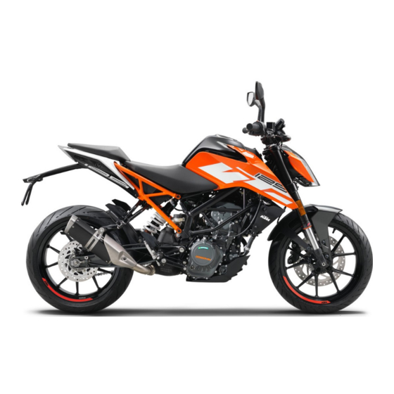
Page 22: View Of Vehicle
4 VIEW OF VEHICLE View of vehicle, front left (example) E01166-10... - Page 23 VIEW OF VEHICLE 4 Combination instrument Rear mirror Clutch lever ( p. 26) Front rider's seat Seat lock ( p. 36) Passenger seat Grab handles ( p. 37) Shift lever ( p. 38) Side stand ( p. 39) Engine number ( p.
-
Page 24: View Of Vehicle, Rear Right (Example)
4 VIEW OF VEHICLE View of vehicle, rear right (example) E01167-10... - Page 25 VIEW OF VEHICLE 4 Tool set ( p. 36) Light switch ( p. 28) Menu switch ( p. 29) Turn signal switch ( p. 29) Horn button ( p. 30) Filler cap Electric starter button ( p. 31) Emergency OFF switch ( p.
-
Page 26: Serial Numbers
5 SERIAL NUMBERS Chassis number The chassis number is stamped on the right side of the steer- ing head. 0 0 1 402408-10 Type label The type label is on the right of the frame behind the steering head. 0 0 1 402174-10... -
Page 27: Engine Number
SERIAL NUMBERS 5 Engine number The engine number is stamped on the left side of the engine under the engine sprocket. 402486-10 Key number The key number can be found on the KEYCODECARD. Info You need the key number to order a spare key. Keep the KEYCODECARD in a safe place. -
Page 28: Controls
6 CONTROLS Clutch lever The clutch lever is fitted on the left side of the handlebar. F00717-10 Hand brake lever The hand brake lever is fitted on the right side of the handle- bar. The front brake is engaged using the hand brake lever. F00718-10... -
Page 29: Throttle Grip
CONTROLS 6 Throttle grip The throttle grip is fitted on the right side of the handlebar. F00718-11 Switches on the left side of the handlebar 6.4.1 Combination switch The combination switch is fitted on the left side of the handlebar. -
Page 30: Light Switch
6 CONTROLS Overview of the left combination switch Light switch ( p. 28) Menu switch ( p. 29) Turn signal switch ( p. 29) Horn button ( p. 30) F00720-10 6.4.2 Light switch Light switch is fitted on the left side of the handlebar. Possible states Low beam on –... -
Page 31: Menu Switch
CONTROLS 6 6.4.3 Menu switch The menu switch is fitted in the middle of the left combination switch. The menu buttons are used to control the display on the combina- tion instrument. Button is the UP button. Button is the DOWN button. Button is the SET button. -
Page 32: Horn Button
6 CONTROLS 6.4.5 Horn button The horn button is fitted on the left side of the handlebar. Possible states • Horn button in neutral position pressed – The horn is operated in this posi- • Horn button tion. F00721-12 Switches on the right side of the handlebar 6.5.1 Emergency OFF switch The emergency OFF switch... -
Page 33: Electric Starter Button
CONTROLS 6 6.5.2 Electric starter button The electric starter button is fitted on the right side of the handlebar. Possible states • Electric starter button in basic position pressed – In this position, the elec- • Electric starter button tric starter is actuated. F00723-10 Ignition/steering lock The ignition/steering lock is in front of the upper triple clamp. -
Page 34: Locking The Steering
6 CONTROLS Locking the steering Note Danger of damage The parked vehicle can roll away or fall over. – Park the vehicle on a firm and level surface. – Park the vehicle. – Turn the handlebar all the way to the left. –... -
Page 35: Unlocking The Steering
CONTROLS 6 Unlocking the steering – Insert the key into the ignition/handlebar lock, press in, and turn to the right. Remove the key. You can now steer the bike again. 400731-01 Opening the filler cap Danger Fire hazard Fuel is highly flammable. The fuel in the fuel tank expands when warm and can escape if overfilled. - Page 36 6 CONTROLS Warning Danger of poisoning Fuel is poisonous and a health hazard. – Avoid skin, eye and clothing contact with fuel. – Immediately consult a doctor if you swallow fuel. – Do not inhale fuel vapors. – In case of skin contact, rinse the affected area with plenty of water. –...
-
Page 37: Closing The Filler Cap
CONTROLS 6 – Remove the ignition key. 6.10 Closing the filler cap Warning Fire hazard Fuel is highly flammable, toxic and a health hazard. – Check the filler cap is locked correctly after clos- ing. – Change your clothing in case of fuel spills on them. –... -
Page 38: Seat Lock
6 CONTROLS 6.11 Seat lock The seat lock is located to the left of the seat. The seat lock can be unlocked using the ignition key. F00728-10 6.12 Tool set The tool set is located under the passenger seat. F00729-10... -
Page 39: Grab Handles
CONTROLS 6 6.13 Grab handles The grab handles are used for moving the motorcycle around. If you carry a passenger, the passenger can hold onto the grab handles during the trip. F00741-10 6.14 Passenger foot pegs The passenger foot pegs can be folded up and down. Possible states Passenger foot pegs folded up –... -
Page 40: Shift Lever
6 CONTROLS 6.15 Shift lever Shift lever is mounted on the left side of the engine. 401950-10 The gear positions can be seen in the photograph. The neutral or idle position is between the first and second gears. 401950-11... -
Page 41: Foot Brake Lever
CONTROLS 6 6.16 Foot brake lever Foot brake lever is located in front of the right footrest. The foot brake lever is used to activate the rear brake. 402177-10 6.17 Side stand Side stand is located on the left of the vehicle. The side stand is used for parking the motorcycle. - Page 42 6 CONTROLS Side stand folded in – This position is mandatory when riding • the motorcycle. The safety start system is disabled.
-
Page 43: Combination Instrument 7
COMBINATION INSTRUMENT 7 Combination instrument The combination instrument is attached in front of the handlebar. The combination instrument is divided into two function areas. indicator lamps ( p. 44) Display 402800-10 Activation and test Activation The combination instrument is activated when the ignition is switched on. -
Page 44: Day-Night Mode
7 COMBINATION INSTRUMENT Day-Night mode Day mode is shown in a bright color. 402803-01 Night mode is shown in a dark color. Info The light sensor in the combination instrument measures the brightness of the environment and automatically switches the display to day or night mode. The display is brightened, darkened or switched to the other mode depending on the brightness measured by the light sensor. -
Page 45: Warning Notes
COMBINATION INSTRUMENT 7 Warning notes Warning notes appear on the top and/or bottom edge of the dis- play, these are marked yellow or red depending on their relevance. Yellow warning notes indicate errors or information which requires prompt intervention or an adjustment to the riding style. Red warning notes indicate errors or information which requires immediate intervention. -
Page 46: Indicator Lamps
7 COMBINATION INSTRUMENT Indicator lamps F00900-01... - Page 47 Malfunction indicator lamp lights up yellow – The OBD has detected an error in the vehicle electronics. Come safely to a halt, and contact an authorized KTM workshop. ABS indicator lamp lights up yellow – Status or error messages relating to ABS.
- Page 48 7 COMBINATION INSTRUMENT The oil pressure warning lamp lights up red – The oil pressure is too low. Stop immediately, taking care not to endanger yourself or other road users in the process, and switch off the engine. Alarm system indicator lamp flashes red – Status message on the alarm system (optional). The high beam indicator lamp lights up blue –...
- Page 49 COMBINATION INSTRUMENT 7...
-
Page 50: Display
7 COMBINATION INSTRUMENT Display F00877-10... - Page 51 COMBINATION INSTRUMENT 7 Speed ( p. 50) Shift warning light ( p. 51) The shift warning light is integrated in the tachometer display. Gear display Unit for the speed display Speed ( p. 52) Unit for the speedometer ODO display ( p.
-
Page 52: Speed
7 COMBINATION INSTRUMENT Speed The speed is measured in revolutions per minute. F00878-12... -
Page 53: Shift Warning Light
COMBINATION INSTRUMENT 7 Shift warning light The shift warning light is integrated in the tachometer display. In the Shift Light menu, the engine speed for the shift warning light can be set. The shift warning light is always active during the running-in phase (up to 1,000 km / 621 mi). -
Page 54: Speed
7 COMBINATION INSTRUMENT RPM2 shift warning flashes light Speed Speed is shown in kilometers per hour km/h or in miles per hour mph. 402806-10... -
Page 55: Odo Display
COMBINATION INSTRUMENT 7 7.10 ODO display The total distance covered ODO is shown in area of the display. Info This value is retained, even if the battery is disconnected from the vehicle or the fuse blows. 402806-12 7.11 Coolant temperature indicator The coolant temperature indicator consists of bars. -
Page 56: Fuel Level Display
7 COMBINATION INSTRUMENT Info When all bars light up, the following warning note ENGINE TEMP HIGH appears. Possible states The engine is cold – Up to three bars light up. • Engine warm – Four to five bars light up. •... -
Page 57: Time
COMBINATION INSTRUMENT 7 Info If the fuel level is getting low, the last segment flashes red and the following warning note also appears LOW FUEL. The fuel level is displayed with a slight delay to prevent the indicator from constantly moving while riding. The fuel level display is not updated while the side stand is folded out or the emergency off switch is switched off. -
Page 58: Favourites Display
7 COMBINATION INSTRUMENT 7.14 Favourites display Up to eight items of information are shown in the Favourites dis- play. The Favourites display can be freely configured in the Favourites menu. Info One to four items of information selected are displayed on two lines. -
Page 59: Quick Selector 2 Display
COMBINATION INSTRUMENT 7 7.16 Quick Selector 2 display When the menu is closed, the Quick Selector 2 menu is opened by pressing the DOWN button. Press the BACK button to close Quick Selector 2. Info The Quick Selector 2 can be configured in the Quick Selec- tor 2 menu. -
Page 60: Ktm My Ride (Optional)
– Press the UP or DOWN button until KTM MY RIDE is marked. Press the SET button to open the menu. In KTM MY RIDE a suitable cellphone can be paired with the com- bination instrument via Bluetooth ® V01160-01... -
Page 61: Info
COMBINATION INSTRUMENT 7 7.17.2 Info – Press the SET button when the menu is closed. – Press the UP or DOWN button until Info is marked. Press the SET button to open the menu. General information can be accessed in Info. V01161-01 7.17.3 Motorcycle... -
Page 62: Settings
7 COMBINATION INSTRUMENT 7.17.4 Settings Condition • The motorcycle is stationary. – Press the SET button when the menu is closed. – Press the UP or DOWN button until Settings is marked. Press the SET button to open the menu. Favorites and quick selection can be configured in Settings. -
Page 63: Pairing (Optional)
– Press the SET button when the menu is closed. – Press the UP or DOWN button until KTM MY RIDE is marked. Press the SET button to open the menu. V01181-01 – Press the UP or DOWN button until Pairing is marked. Press the SET button to open the menu. -
Page 64: Audio (Optional)
– Press the SET button when the menu is closed. – Press the UP or DOWN button until KTM MY RIDE is marked. Press the SET button to open the menu. V01165-01... - Page 65 COMBINATION INSTRUMENT 7 Warning Danger of accidents Headphone volume which is too high distracts attention from traffic activity. – Always select headphone volume which is low enough for you to still clearly hear acoustic signals. – Press the UP or DOWN button until Audio is marked. Press the SET button to open the menu.
-
Page 66: Telephony (Optional)
7 COMBINATION INSTRUMENT 7.17.8 Telephony (optional) Condition • Function KTM MY RIDE activated (optional). • Function Bluetooth ® activated. • The Bluetooth ® function should also be activated in the device to be paired. • Headset linked with appropriate cellphone. -
Page 67: General Info
COMBINATION INSTRUMENT 7 7.17.9 General Info – Press the SET button when the menu is closed. – Press the UP or DOWN button until Info is marked. Press the SET button to open the menu. – Press the UP or DOWN button until General Info is marked. Press the SET button to open the menu. -
Page 68: Trip 2
7 COMBINATION INSTRUMENT Fuel Range indicates the possible distance you can cover with the fuel reserve. Press and All entries in the Trip 1 menu are reset. hold the SET button for 3-5 seconds. 7.17.11 Trip 2 – Press the SET button when the menu is closed. –... -
Page 69: Warning
COMBINATION INSTRUMENT 7 Press and All entries in the Trip 2 menu are reset. hold the SET button for 3-5 seconds. 7.17.12 Warning Condition • Message or warning is present. – Press the SET button when the menu is closed. –... -
Page 70: Abs
7 COMBINATION INSTRUMENT 7.17.13 ABS Condition • The motorcycle is stationary. – Press the SET button when the menu is closed. – Press the UP or DOWN button until Motorcycle is marked. Press the SET button to open the menu. Note Voiding of the government approval for road use and the insurance coverage If the ABS is switched off completely, the vehicle's... -
Page 71: Favourites
COMBINATION INSTRUMENT 7 Press and Switching off ABS. hold the SET button for 3-5 seconds. 7.17.14 Favourites Condition • The motorcycle is stationary. – Press the SET button when the menu is closed. – Press the UP or DOWN button until Settings is marked. Press the SET button to open the menu. -
Page 72: Quick Selector 1
7 COMBINATION INSTRUMENT 7.17.15 Quick Selector 1 Condition • The motorcycle is stationary. – Press the SET button when the menu is closed. – Press the UP or DOWN button until Settings is marked. Press the SET button to open the menu. –... -
Page 73: Bluetooth
V01171-01 off. Info The Bluetooth ® function can only be used in conjunction with KTM MY RIDE (optional). When the Bluetooth ® function is switched on and the device is connected, the Bluetooth ® symbol appears in the display... -
Page 74: Shift Light
7 COMBINATION INSTRUMENT 7.17.18 Shift Light Condition • The motorcycle is stationary. • ODO > 1000 km (621 m). – Press the SET button when the menu is closed. – Press the UP or DOWN button until Preferences is marked. Press the SET button to open the menu. - Page 75 COMBINATION INSTRUMENT 7 – Press the SET button when the menu is closed. – Press the UP or DOWN button until Preferences appears. Press the SET button to open the menu. – Press the UP or DOWN button until Clock/Date is marked. Press the SET button to open the menu.
- Page 76 7 COMBINATION INSTRUMENT Setting the date – Press the UP or DOWN button until the date is marked. – Press the SET button. The day flashes and is underlined. – Press the UP or DOWN button until the current day is set. –...
-
Page 77: Drl
COMBINATION INSTRUMENT 7 7.17.20 DRL Condition • The motorcycle is stationary. – Press the SET button when the menu is closed. – Press the UP or DOWN button until Preferences is marked. Press the SET button to open the menu. Warning Danger of accidents When visibility is poor, the day- time running light is not a substitute for the low beam. -
Page 78: Distance
7 COMBINATION INSTRUMENT – Press the UP or DOWN button until DRL is marked. Press the SET button to open the menu. – Activate the menu item using the UP or DOWN button. – Press the SET button to switch the daytime running light on or off. -
Page 79: Temperature
COMBINATION INSTRUMENT 7 7.17.22 Temperature Condition • The motorcycle is stationary. – Press the SET button when the menu is closed. – Press the UP or DOWN button until Preferences is marked. Press the SET button to open the menu. –... -
Page 80: Language
7 COMBINATION INSTRUMENT – Activate the menu item using the UP or DOWN button. – Press the SET button to confirm the desired unit. 7.17.24 Language Condition • The motorcycle is stationary. – Press the SET button when the menu is closed. –... -
Page 81: Service
COMBINATION INSTRUMENT 7 7.17.25 Service Condition • The motorcycle is stationary. – Press the SET button when the menu is closed. – Press the UP or DOWN button until Preferences is marked. Press the SET button to open the menu. –... - Page 82 7 COMBINATION INSTRUMENT Info The current KTM PowerParts and the available software for your vehicle can be found on the KTM website.
-
Page 83: Preparing For Use 8
Make sure that only tires with a similar tire tread pattern are fitted to the front and rear wheel. Warning Danger of accidents Non-approved or non-recommended tires and wheels impact the handling character- istic. – Only use tires/wheels approved by KTM with the corresponding speed index. - Page 84 When using the vehicle, remember that others may feel disturbed by excessive noise. – Ensure that the pre-delivery inspection work has been carried out by an authorized KTM workshop. The delivery certificate and the Service and Manufacturer Warranty Booklet must be transferred with the vehicle.
-
Page 85: Running In The Engine
PREPARING FOR USE 8 Running in the engine – During the running-in phase, do not exceed the specified engine speed. Guideline Maximum engine speed During the first: 1,000 km (620 mi) 7,500 rpm Info During the running-in phase, the shift warning light is set to a specified value and cannot be changed. –... - Page 86 8 PREPARING FOR USE Warning Danger of accidents Improper mounting of cases or the tank rucksack impairs the handling characteris- tic. – Mount and secure cases and tank rucksack according to the manufacturer's instructions. Warning Danger of accidents The luggage system will be damaged if it is overloaded. –...
- Page 87 PREPARING FOR USE 8 – If luggage is carried, ensure it is fixed firmly as close as possible to the center of the vehicle and ensure even weight distribution between the front and rear wheels. – Do not exceed maximum permissible weight and maximum permissible axle loads. Guideline Maximum permissible overall weight 355 kg (783 lb.)
-
Page 88: Riding Instructions
9 RIDING INSTRUCTIONS Checks and maintenance measures when preparing for use Info Before every trip, check the condition of the vehicle and ensure that it is roadworthy. The vehicle must be in perfect technical condition when it is being operated. –... -
Page 89: Starting
RIDING INSTRUCTIONS 9 Starting Danger Danger of poisoning Exhaust gases are toxic and inhaling them may result in unconsciousness and death. – Always make sure there is sufficient ventilation when running the engine. – Use an effective exhaust extraction system when starting or running the engine in an enclosed space. Caution Danger of accidents Electronic components and safety devices will be damaged if the battery is discharged or missing. - Page 90 9 RIDING INSTRUCTIONS – Unlock the steering. ( p. 33) – Sit on the vehicle, take the weight off of the side stand, and move up all the way. – Turn the emergency OFF switch to the position – Switch on the ignition by turning the ignition key to the posi- tion After you switch on the ignition, you can hear the fuel pump working for about two seconds.
-
Page 91: Starting Off
RIDING INSTRUCTIONS 9 Info Do not press the electric starter button until the combi- nation instrument function check is finished. When starting, DO NOT open the throttle. If you open the throttle during the starting procedure, fuel is not injected by the engine management system and the engine cannot start. -
Page 92: Shifting, Riding
9 RIDING INSTRUCTIONS Shifting, riding Warning Danger of accidents Abrupt load alterations can cause the vehicle to get out of control. – Avoid abrupt load alterations and sudden braking actions. – Adapt your speed to the road conditions. Warning Danger of accidents If you change down at high engine speed, the rear wheel blocks and the engine races. - Page 93 RIDING INSTRUCTIONS 9 Warning Risk of injury The passenger may fall from the motorcycle if they conduct themselves incorrectly. – Ensure that the passenger sits correctly on the passenger seat, places his or her feet on the passenger foot pegs and holds on to the rider or the grab handles. –...
- Page 94 Check and, if necessary, correct the coolant level on the cooling system while it is in a cooled state. Info If unusual noises occur while riding, stop immediately (taking care not to endanger yourself or other road users in the process), switch off the engine and contact an authorized KTM workshop.
- Page 95 RIDING INSTRUCTIONS 9 – Shift into a higher gear when conditions allow (incline, road situation, etc.). – Release the throttle while simultaneously pulling the clutch lever, shift into the next gear, release the clutch lever, and open the throttle. Info The gear positions can be seen in the figure.
- Page 96 Contact an authorized KTM workshop. – If the malfunction indicator lamp lights up during a trip, please contact an authorized KTM workshop as soon as possi- ble. – If the general warning lamp lights up during a trip, an oper- ating safety (warning) message was detected.
-
Page 97: Applying The Brakes
Danger of accidents A spongy pressure point on the front or rear brake reduces braking efficiency. – Check the brake system and do not continue riding until the problem is eliminated. (Your authorized KTM workshop will be glad to help.) Warning Danger of accidents The brake system fails in the event of overheating. - Page 98 9 RIDING INSTRUCTIONS Warning Danger of accidents ABS may increase the stopping distance in certain situations. – Adjust application of the brakes to the respective riding situation and riding surface conditions. Warning Danger of accidents Excessively forceful application of the brakes blocks the wheels. The ABS effectiveness is only ensured if it is switched on.
-
Page 99: Stopping, Parking
RIDING INSTRUCTIONS 9 – Use the braking effect of the engine on long downhill stretches. Shift back one or two gears, but do not over- rev the engine when doing so. This means that significantly less braking is required and the brake system does not overheat. -
Page 100: Transport
9 RIDING INSTRUCTIONS Note Fire hazard Hot vehicle components pose a fire hazard and explosion risk. – Do not park the vehicle near to materials which are highly flammable or explosive. – Allow the vehicle to cool down before covering it. –... - Page 101 RIDING INSTRUCTIONS 9 Note Fire hazard Hot vehicle components pose a fire hazard and explosion risk. – Do not park the vehicle near to materials which are highly flammable or explosive. – Allow the vehicle to cool down before covering it. –...
-
Page 102: Refueling
9 RIDING INSTRUCTIONS Refueling Danger Fire hazard Fuel is highly flammable. The fuel in the fuel tank expands when warm and can escape if overfilled. – Do not refuel the vehicle in the vicinity of open flames or lit cigarettes. – Switch off the engine for refueling. - Page 103 In some countries and regions, the available fuel quality and cleanliness may not be sufficient. This will result in problems with the fuel system. – Refuel only with clean fuel that meets the specified standards. (Your authorized KTM workshop will be glad to help.) Note Environmental hazard Improper handling of fuel is a danger to the environment.
-
Page 104: Service Schedule
Different service intervals may apply in your country, depending on the local operating conditions. Individual service intervals and scopes may change in the course of technical developments. The most up-to-date service schedule can always be found on KTM Dealer.net. Your authorized KTM dealer will be happy to advise you. - Page 105 SERVICE SCHEDULE 10 Every two years Every year every 15,000 km (9,300 mi) every 7,500 km (4,650 mi) after 1,000 km (620 mi) ○ ● ● ● Check the rear brake fluid level. ( p. 141) ○ ● ● ● ●...
-
Page 106: Recommended Work
● ● Set the service interval display. ○ ● ● ● ● Make the service entry in the KTM Dealer.net and in the Service and Warranty Booklet. ○ One-time interval ● Periodic interval 10.3 Recommended work Every four years Every year... - Page 107 SERVICE SCHEDULE 10 Every four years Every year every 30,000 km (18,600 mi) every 7,500 km (4,650 mi) after 1,000 km (620 mi) ● Check the swingarm. ● ● Check the swingarm bearing for play. ● ● Check the wheel bearing for play. ○...
-
Page 108: Tuning The Chassis
11 TUNING THE CHASSIS 11.1 Adjusting the spring preload of the shock absorber Warning Danger of accidents Modifications to the suspension setting may seriously alter the handling characteris- tic. – Ride slowly to start with after making adjustments to get the feel of the new handling characteristic. Info The spring preload defines the initial status of the spring operation on the shock absorber. -
Page 109: Adjusting The Shift Lever
TUNING THE CHASSIS 11 11.2 Adjusting the shift lever Info The adjustment range of the shift lever is limited. – Loosen nuts – Adjust the shift lever by turning shift rod Guideline Shift rod adjustment range 90 … 102 mm (3.54 … 4.02 in) Info Make the same adjustments on both sides. - Page 110 11 TUNING THE CHASSIS Info After the nuts have been tightened, the bearings of the shift rod must be central and aligned identically to each other in order to ensure freedom of movement in the bearing shells. – Check the shift lever to ensure it is functioning properly and can move freely.
-
Page 111: Service Work On The Chassis 12
SERVICE WORK ON THE CHASSIS 12 12.1 Raising the motorcycle with the rear lifting gear Note Danger of damage The parked vehicle can roll away or fall over. – Park the vehicle on a firm and level surface. – Mount the supports of the lifting gear. –... -
Page 112: Lifting The Motorcycle With The Front Lifting Gear
12 SERVICE WORK ON THE CHASSIS – Secure the motorcycle against falling over. – Remove the rear lifting gear and lean the vehicle on side stand – Remove bushings kit. 402029-10 12.3 Lifting the motorcycle with the front lifting gear Note Danger of damage The parked vehicle can roll away or fall over. - Page 113 SERVICE WORK ON THE CHASSIS 12 Condition – Remove protection cap F00735-10 – Move the handlebar to the straight-ahead position. Position the lifting gear. Mounting pin (69329965030) Front wheel work stand, large (69329965000) Info Always raise the motorcycle at the rear first. –...
-
Page 114: Taking The Motorcycle Off The Front Lifting Gear
12 SERVICE WORK ON THE CHASSIS 12.4 Taking the motorcycle off the front lifting gear Note Danger of damage The parked vehicle can roll away or fall over. – Park the vehicle on a firm and level surface. Main work – Secure the motorcycle against falling over. -
Page 115: Cleaning The Dust Boots Of The Fork Legs
SERVICE WORK ON THE CHASSIS 12 – Mount protection cap F00735-10 Finishing work – Remove the rear of the motorcycle from the lifting gear. p. 109) 12.5 Cleaning the dust boots of the fork legs Preparatory work – Raise the motorcycle with the rear lifting gear. ( p. - Page 116 12 SERVICE WORK ON THE CHASSIS Main work – Push dust boots of both fork legs downward. Info The dust boots should remove dust and coarse dirt par- ticles from the fork tubes. Over time, dirt can accumu- late behind the dust boots. If this dirt is not removed, the oil seals behind can start to leak.
-
Page 117: Removing The Passenger Seat
SERVICE WORK ON THE CHASSIS 12 – Remove the rear of the motorcycle from the lifting gear. p. 109) 12.6 Removing the passenger seat – Insert the ignition key in seat lock and turn it clockwise. – Raise the rear of the seat, push it towards the rear, and lift it off. -
Page 118: Mounting The Passenger Seat
12 SERVICE WORK ON THE CHASSIS 12.7 Mounting the passenger seat – Attach hooks on the passenger seat to seat mounting on the subframe, and lower it at the rear while pushing for- ward. – Press down the passenger seat cover until it clicks into place. Warning Danger of accidents The seat can come loose from the anchoring if it is not mounted correctly. -
Page 119: Mounting The Front Rider's Seat
SERVICE WORK ON THE CHASSIS 12 Main work – Raise the rear of the front rider's seat, pull it towards the rear, and remove it upwards. H01993-01 12.9 Mounting the front rider's seat Main work – Attach the front rider's seat in area and lower at the rear. -
Page 120: Checking For Chain Dirt Accumulation
12 SERVICE WORK ON THE CHASSIS 12.10 Checking for chain dirt accumulation – Check the chain for coarse dirt accumulation. » If the chain is very dirty: – Clean the chain. ( p. 118) 400678-01 12.11 Cleaning the chain Warning Danger of accidents Oil or grease on the tires reduces the road grip. - Page 121 SERVICE WORK ON THE CHASSIS 12 Note Environmental hazard Hazardous substances cause environmental damage. – Dispose of oils, grease, filters, fuel, cleaning agents, brake fluid, etc., correctly and in compliance with the applicable regulations. Info The service life of the chain depends largely on its maintenance. Preparatory work –...
-
Page 122: Checking The Chain Tension
12 SERVICE WORK ON THE CHASSIS 12.12 Checking the chain tension Warning Danger of accidents Incorrect chain tension damages components and results in accidents. If the chain is tensioned too much, the chain, engine sprocket, rear sprocket, transmission and rear wheel bearings wear more quickly. Some components may break if overloaded. If the chain is too loose, the chain may fall off the engine sprocket or the rear sprocket. -
Page 123: Adjusting The Chain Tension
SERVICE WORK ON THE CHASSIS 12 » If the chain tension does not meet the specification: – Adjust the chain tension. ( p. 121) – Remove the rear of the motorcycle from the lifting gear. p. 109) 12.13 Adjusting the chain tension Warning Danger of accidents Incorrect chain tension damages components and results in accidents. - Page 124 12 SERVICE WORK ON THE CHASSIS Main work – Loosen nut – Loosen nuts – Adjust the chain tension by turning adjusting screws left and right. Guideline Chain tension 5 … 7 mm (0.2 … 0.28 in) Turn the adjusting screws on the left and right so that the markings on the left and right chain adjusters are in...
-
Page 125: Checking The Chain, Rear Sprocket, And Engine Sprocket
SERVICE WORK ON THE CHASSIS 12 Finishing work – Remove the rear of the motorcycle from the lifting gear. p. 109) 12.14 Checking the chain, rear sprocket, and engine sprocket Preparatory work – Raise the motorcycle with the rear lifting gear. ( p. - Page 126 12 SERVICE WORK ON THE CHASSIS – Shift gear to neutral. – Pull the lower chain section with specified weight Guideline Weight, chain wear measure- 15 kg (33 lb.) ment – Measure distance of 20 chain rollers in the lower chain section.
- Page 127 SERVICE WORK ON THE CHASSIS 12 – Check the chain sliding guard for wear. » If in area by the chain sliding guard screw is visi- ble from above: – Change the chain sliding guard. – Check that the chain sliding guard is firmly seated. »...
-
Page 128: Removing The Front Spoiler
12 SERVICE WORK ON THE CHASSIS 12.15 Removing the front spoiler – Remove screws F00740-10 – Remove screws – Take off the front spoiler. F00739-10... -
Page 129: Fitting Front Spoiler
SERVICE WORK ON THE CHASSIS 12 12.16 Fitting front spoiler – Position the front spoiler. Mount screws but do not tighten yet. F00740-10 – Mount and tighten screws Guideline Screw, front spoiler M6x9 9 Nm (6.6 lbf ft) rear – Tighten screws Guideline Screw, front spoiler... -
Page 130: Brake System
Do not make any changes to the suspension travel. – Only use spare parts on the brake system which have been approved and recommended by KTM. – Only use tires/wheels approved by KTM with the corre- sponding speed index. – Maintain the specified tire air pressure. –... - Page 131 BRAKE SYSTEM 13 Note Voiding of the government approval for road use and the insurance coverage If the ABS is switched off completely, the vehicle's approval for road use is invalidated. – Only operate the vehicle in closed-off areas remote from public road traffic if the ABS is switched off completely.
-
Page 132: Checking The Brake Discs
ABS indicator lamp goes out when you start off. 13.2 Checking the brake discs Warning Danger of accidents Worn-out brake discs reduce the braking effect. – Make sure that worn-out brake discs are replaced immediately. (Your authorized KTM workshop will be glad to help.) - Page 133 BRAKE SYSTEM 13 – Check the front and rear brake disc thickness at multiple points for the dimension Info Wear will reduce the thickness of the brake disc at con- tact surface of the brake linings. Brake discs - wear limit front 4.5 mm (0.177 in) 400480-10...
-
Page 134: Checking The Brake Fluid Level Of The Front Brake
– Make sure that brake fluid for the front and rear brake is changed in accordance with the service schedule. (Your authorized KTM workshop will be glad to help.) – Move the brake fluid reservoir mounted on the handlebar to a horizontal position. -
Page 135: Adding Front Brake Fluid
If the brake fluid level drops below the MIN marking, the brake system is leaking or the brake linings are worn down. – Check the brake system and do not continue riding until the problem is eliminated. (Your authorized KTM workshop will be glad to help.) Warning Skin irritation Brake fluid causes skin irritation. –... - Page 136 Danger of accidents Old brake fluid reduces the braking effect. – Make sure that brake fluid for the front and rear brake is changed in accordance with the service schedule. (Your authorized KTM workshop will be glad to help.) Note Environmental hazard Hazardous substances cause environmental damage.
- Page 137 BRAKE SYSTEM 13 Main work – Move the brake fluid reservoir mounted on the handlebar to a horizontal position. – Remove screws – Remove cover with membrane – Add brake fluid to level Guideline 5 mm (0.2 in) Level F00747-10 Brake fluid DOT 4 / DOT 5.1 ( p.
-
Page 138: Checking The Front Brake Linings
Checking the front brake linings Warning Danger of accidents Worn-out brake linings reduce the braking effect. – Ensure that worn-out brake linings are replaced immediately. (Your authorized KTM workshop will be glad to help.) Warning Danger of accidents Damaged brake discs reduce the braking effect. -
Page 139: Checking The Free Travel Of Foot Brake Lever
BRAKE SYSTEM 13 13.6 Checking the free travel of foot brake lever Warning Danger of accidents The brake system fails in the event of overheating. If there is no free travel on the foot brake lever, pressure builds up in the brake system on the rear brake. - Page 140 13 BRAKE SYSTEM – Disconnect spring – Move the foot brake lever back and forth between the end stop and the contact to the foot brake cylinder piston and check free travel Guideline Free travel at foot brake lever 3 … 5 mm (0.12 … 0.2 in) »...
-
Page 141: Adjusting The Free Travel Of The Foot Brake Lever
BRAKE SYSTEM 13 13.7 Adjusting the free travel of the foot brake lever Warning Danger of accidents The brake system fails in the event of overheating. If there is no free travel on the foot brake lever, pressure builds up in the brake system on the rear brake. - Page 142 13 BRAKE SYSTEM – Detach spring – Release nut and use screw to adjust the specified free travel Guideline Free travel at foot brake lever 3 … 5 mm (0.12 … 0.2 in) Info The range of adjustment is limited. –...
-
Page 143: Checking The Rear Brake Fluid Level
Danger of accidents Old brake fluid reduces the braking effect. – Make sure that brake fluid for the front and rear brake is changed in accordance with the service schedule. (Your authorized KTM workshop will be glad to help.) – Stand the vehicle upright. -
Page 144: Adding Rear Brake Fluid
If the brake fluid level drops below the MIN marking, the brake system is leaking or the brake linings are worn down. – Check the brake system and do not continue riding until the problem is eliminated. (Your authorized KTM workshop will be glad to help.) Warning Skin irritation Brake fluid causes skin irritation. –... - Page 145 Danger of accidents Old brake fluid reduces the braking effect. – Make sure that brake fluid for the front and rear brake is changed in accordance with the service schedule. (Your authorized KTM workshop will be glad to help.) Note Environmental hazard Hazardous substances cause environmental damage.
- Page 146 13 BRAKE SYSTEM Condition The screw cap is locked. – Remove screw and take off the screw cap lock. H01142-10 – Stand the vehicle upright. – Remove screw cap with membrane – Add brake fluid to level Brake fluid DOT 4 / DOT 5.1 ( p.
-
Page 147: Checking The Rear Brake Linings
Checking the rear brake linings Warning Danger of accidents Worn-out brake linings reduce the braking effect. – Ensure that worn-out brake linings are replaced immediately. (Your authorized KTM workshop will be glad to help.) Warning Danger of accidents Damaged brake discs reduce the braking effect. - Page 148 13 BRAKE SYSTEM – Check the brake linings for minimum thickness ≥ 1 mm (≥ 0.04 in) Minimum thickness » If the minimum thickness is less than specified: – Change the rear brake linings. – Check the brake linings for damage and cracking. »...
-
Page 149: Wheels, Tires 14
WHEELS, TIRES 14 14.1 Removing the front wheel Preparatory work – Raise the motorcycle with the rear lifting gear. ( p. 109) – Lift the motorcycle with the front lifting gear. ( p. 110) Main work – Remove screws with washers and push the fender slightly to the side. -
Page 150: Installing The Front Wheel
14 WHEELS, TIRES Info Do not pull the hand brake lever when the front wheel is removed. 14.2 Installing the front wheel Warning Danger of accidents Oil or grease on the brake discs reduces the braking effect. – Always keep the brake discs free of oil and grease. –... - Page 151 WHEELS, TIRES 14 – Clean the thread of the wheel spindle and screw – Clean and grease wheel spindle. Long-life grease ( p. 238) – Position the front wheel and insert the wheel spindle. The brake linings are correctly positioned. –...
-
Page 152: Removing The Rear Wheel
14 WHEELS, TIRES – Remove the rear of the motorcycle from the lifting gear. p. 109) – Operate the front brake and compress the fork a few times firmly. The fork legs straighten. – Tighten screws Guideline Screw, fork stub 15 Nm (11.1 lbf ft) 14.3 Removing the rear wheel... - Page 153 WHEELS, TIRES 14 – Remove screw and pull wheel speed sensor out of the hole. – Remove nut and washer. – Remove chain adjuster – Holding the rear wheel, withdraw wheel spindle with the washer and chain adjuster – Push the rear wheel forward as far as possible and take the chain off the rear sprocket.
-
Page 154: Installing The Rear Wheel
14 WHEELS, TIRES 14.4 Installing the rear wheel Warning Danger of accidents Oil or grease on the brake discs reduces the braking effect. – Always keep the brake discs free of oil and grease. – Clean the brake discs with brake cleaner when necessary. Warning Danger of accidents There is no braking effect to start with at the rear brake after installing the rear wheel. - Page 155 WHEELS, TIRES 14 Long-life grease ( p. 238) – Clean the contact areas of the brake caliper support and swingarm. – Mount the rubber damper and rear sprocket carrier on the rear wheel. – Insert the spacers. – Position the rear wheel. The brake linings are correctly positioned.
- Page 156 14 WHEELS, TIRES – Pull the rear wheel back and mount wheel spindle with the washer and chain adjuster Guideline Mount left and right chain adjusters in the same posi- tion. – Mount nut and washer. – Push the rear wheel forward so that the chain adjusters are in contact with the screws, and tighten nut Guideline In order for the rear wheel to be correctly aligned, the mark-...
-
Page 157: Checking The Rear Hub Rubber Dampers
WHEELS, TIRES 14 – Mount and tighten screw Guideline Screw, chain guard EJOT PT ® 7 Nm (5.2 lbf ft) K60x30 F00776-11 Finishing work – Remove the rear of the motorcycle from the lifting gear. p. 109) – Check the chain tension. ( p. - Page 158 14 WHEELS, TIRES Main work – Check bearing » If the bearing is damaged or worn: – Change the bearing. – Check the rubber dampers of the rear hub for damage and wear. » If the rubber dampers of the rear hub are damaged or worn: F00756-10 –...
-
Page 159: Checking The Tire Condition
Warning Danger of accidents If a tire bursts while riding, the vehicle becomes uncontrollable. – Ensure that damaged or worn tires are replaced immediately. (Your authorized KTM workshop will be glad to help.) Warning Danger of crashing Different tire tread patterns on the front and rear wheel impair the handling charac- teristic. - Page 160 14 WHEELS, TIRES Info The type, condition, and air pressure of the tires all have a major impact on the handling of the motorcy- cle. Worn tires have a negative effect on handling characteristics, especially on wet surfaces. – Check the front and rear tires for cuts, run-in objects, and other damage.
-
Page 161: Checking The Tire Air Pressure
DOT number. The first two digits indicate the week of manufacture and the last two digits the year of manu- facture. KTM recommends that the tires be changed after 5 H01144-10 years at the latest, regardless of the actual state of wear. - Page 162 14 WHEELS, TIRES – Remove the dust cap. – Check tire air pressure when the tires are cold. Tire air pressure, solo front 2.0 bar (29 psi) rear 2.0 bar (29 psi) Tire air pressure with passenger / full payload front 2.0 bar (29 psi) 400695-01...
-
Page 163: Electrical System 15
ELECTRICAL SYSTEM 15 15.1 Daytime running light (DRL) Warning Danger of accidents When visibility is poor, the daytime running light is not a substitute for the low beam. Automatic switching between the daytime running light and low beam may only be partially available when visi- bility is significantly impaired due to fog, snow or rain. -
Page 164: Removing The Battery
15 ELECTRICAL SYSTEM Control is provided by the brightness sensor in the combination instrument. When visibility conditions are good, the low beam is switched off and the daytime running light is switched on. Info The position light lights up with all types of lighting. 15.2 Removing the battery Warning... - Page 165 ELECTRICAL SYSTEM 15 Main work – Disconnect negative cable from the battery. V01273-10 – Pull back positive terminal cover – Disconnect positive cable from the battery. – Detach rubber band – Pull the battery up and out of the battery holder. Info Never operate the motorcycle with a discharged battery or without a battery.
-
Page 166: Installing The Battery
15 ELECTRICAL SYSTEM 15.3 Installing the battery Main work – Position the battery in the battery holder. Battery (ETZ-9-BS) ( p. 221) – Reconnect rubber band – Position positive cable and mount and tighten the screw. – Position positive terminal cover V01274-11 –... -
Page 167: Recharging The Battery
ELECTRICAL SYSTEM 15 – Set the time and date. ( p. 72) 15.4 Recharging the battery Warning Risk of injury Battery acid and battery gases cause serious chemical burns. – Keep batteries out of the reach of children. – Wear suitable protective clothing and safety glasses. –... - Page 168 15 ELECTRICAL SYSTEM Info Even when there is no load on the battery, it discharges steadily. The charging level and the method of charging are very important for the service life of the battery. Rapid recharging with a high charging current shortens the service life of the battery. If the charging current, charging voltage, or charging time is exceeded, electrolyte escapes through the safety valves.
- Page 169 ELECTRICAL SYSTEM 15 Main work – Connect the battery charger to the battery. Switch on the bat- tery charger. Battery charger (58429074000) In addition, this battery charger can be used to test the open- circuit voltage, the starting ability of the battery, and the alter- nator.
-
Page 170: Changing The Abs Fuses
15 ELECTRICAL SYSTEM Finishing work – Mount the front rider's seat. ( p. 117) – Mount the passenger seat. ( p. 116) – Set the time and date. ( p. 72) 15.5 Changing the ABS fuses Warning Fire hazard Incorrect fuses overload the electrical system. –... - Page 171 ELECTRICAL SYSTEM 15 To change the fuse of the ABS hydraulic unit: – Take off the protection cap and remove fuse Info A faulty fuse has a burned-out fuse wire Warning Fire hazard Incorrect fuses overload the electrical F00758-10 system. – Only use fuses with the required ampere value.
- Page 172 15 ELECTRICAL SYSTEM To change the fuse of the ABS return pump: – Take off the protection cap and remove fuse Info A faulty fuse has a burned-out fuse wire Warning Fire hazard Incorrect fuses overload the electrical F00758-11 system. – Only use fuses with the required ampere value.
-
Page 173: Changing The Fuses Of Individual Power Consumers
ELECTRICAL SYSTEM 15 15.6 Changing the fuses of individual power consumers Info The fuse box with the main fuse and the fuses of the individual power consumers is located under the pas- senger seat. Preparatory work – Switch off the ignition by turning the ignition key to the posi- tion –... - Page 174 15 ELECTRICAL SYSTEM Main work – Open fuse box cover – Remove the faulty fuse. Guideline Fuse 1 - 30 A - main fuse Fuse 2 - 10 A - combination instrument Fuse 3 - 10 A - power relay Fuse 4 - 15 A - ignition coil, fuel pump, start auxiliary relay, horn Fuse 5 - 10 A - radiator fan...
- Page 175 ELECTRICAL SYSTEM 15 Warning Fire hazard Incorrect fuses overload the electrical sys- tem. – Only use fuses with the required ampere value. – Do not bypass or repair fuses. – Use spare fuses with the correct rating only. Fuse (75011088010) ( p.
-
Page 176: Checking The Headlight Setting
15 ELECTRICAL SYSTEM 15.7 Checking the headlight setting – Position the vehicle upright on a horizontal surface in front of 0 0 A a light wall and make a marking at the height of the center of the low beam headlight. –... -
Page 177: Adjusting The Headlight Range
ELECTRICAL SYSTEM 15 15.8 Adjusting the headlight range Preparatory work – Check the headlight setting. ( p. 174) Main work – Turn adjusting screw to adjust the headlight range. Info Turn clockwise to increase the headlight range; turn counterclockwise to reduce the headlight range. If you have a payload, you may have to correct the headlight range. -
Page 178: Diagnostics Connector
15 ELECTRICAL SYSTEM 15.9 Diagnostics connector Diagnostics connector is located under the passenger seat. H01906-10... -
Page 179: Cooling System 16
COOLING SYSTEM 16 16.1 Cooling system Water pump in the engine ensures forced circulation of the coolant. The pressure resulting from the warming of the cooling system is regulated by a valve in radiator cap . Heat expansion causes excess coolant to flow into compensating tank . - Page 180 16 COOLING SYSTEM The coolant is cooled by the air stream and a radiator fan which is activated at high temperature. The lower the speed, the less the cooling effect. Dirty cooling fins also reduce the cooling effect. H01904-10...
-
Page 181: Checking The Antifreeze And Coolant Level
COOLING SYSTEM 16 16.2 Checking the antifreeze and coolant level Warning Danger of scalding During motorcycle operation, the coolant gets very hot and is under pressure. – Do not open the radiator, the radiator hoses or other cooling system components if the engine or the cooling system are at operating temperature. - Page 182 16 COOLING SYSTEM – Stand the motorcycle upright on a horizontal surface. – Remove cap of the compensating tank. – Check the antifreeze in the coolant. −25 … −45 °C (−13 … −49 °F) » If the antifreeze in the coolant does not match the speci- fied value: –...
- Page 183 COOLING SYSTEM 16 – Remove radiator cap – Check the antifreeze in the coolant. −25 … −45 °C (−13 … −49 °F) » If the antifreeze in the coolant does not match the speci- fied value: – Correct the antifreeze in the coolant. –...
-
Page 184: Checking The Coolant Level
16 COOLING SYSTEM 16.3 Checking the coolant level Warning Danger of scalding During motorcycle operation, the coolant gets very hot and is under pressure. – Do not open the radiator, the radiator hoses or other cooling system components if the engine or the cooling system are at operating temperature. - Page 185 COOLING SYSTEM 16 – Stand the motorcycle upright on a horizontal surface. – Check the coolant level in compensating tank The coolant level must be between the two markings. » If the coolant level does not match the specified value: –...
-
Page 186: Draining The Coolant
16 COOLING SYSTEM 16.4 Draining the coolant Warning Danger of scalding During motorcycle operation, the coolant gets very hot and is under pressure. – Do not open the radiator, the radiator hoses or other cooling system components if the engine or the cooling system are at operating temperature. -
Page 187: Filling/Bleeding The Cooling System
COOLING SYSTEM 16 Main work – Position the motorcycle upright. – Place a suitable container under the engine. – Remove screw – Remove the radiator cap. – Completely drain the coolant. – Mount and tighten screw with a new seal ring. Guideline F00765-10 Screw plug, water... - Page 188 16 COOLING SYSTEM Main work – Remove radiator cap F00763-11 – Loosen bleeder screw Guideline 3 turns – Tilt the vehicle slightly to the right. – Pour in coolant until it emerges without bubbles at the bleeder screw, and then mount and tighten the bleeder screw immedi- ately.
- Page 189 COOLING SYSTEM 16 Danger Danger of poisoning Exhaust gases are toxic and inhal- ing them may result in unconsciousness and death. – Always make sure there is sufficient ventilation when running the engine. – Use an effective exhaust extraction system when starting or running the engine in an enclosed space.
-
Page 190: Changing The Coolant
16 COOLING SYSTEM 16.6 Changing the coolant Warning Danger of scalding During motorcycle operation, the coolant gets very hot and is under pressure. – Do not open the radiator, the radiator hoses or other cooling system components if the engine or the cooling system are at operating temperature. - Page 191 COOLING SYSTEM 16 Main work – Position the motorcycle upright. – Place a suitable container under the engine. – Remove screw F00765-10 – Remove radiator cap – Completely drain the coolant. – Mount and tighten screw with a new seal ring. Guideline Screw plug, water 10 Nm (7.4 lbf ft)
- Page 192 16 COOLING SYSTEM – Loosen bleeder screw Guideline 3 turns – Tilt the vehicle slightly to the right. – Pour in coolant until it emerges without bubbles at the bleeder screw, and then mount and tighten the bleeder screw immedi- ately.
- Page 193 COOLING SYSTEM 16 – Stop the engine and allow it to cool down. – When the engine is cool, check the coolant level in the radiator and, if necessary, add coolant. – Remove the cover of compensating tank and top up the coolant level up to the MAX marking.
-
Page 194: Tuning The Engine
17 TUNING THE ENGINE 17.1 Checking the play in the throttle cable – Check the throttle grip for smooth operation. – Move the handlebar to the straight-ahead position. Turn the throttle grip back and forth slightly and determine the play in throttle cable 3 …... -
Page 195: Adjusting The Play In The Throttle Cable
TUNING THE ENGINE 17 – Check throttle cable routing. 17.2 Adjusting the play in the throttle cable – Move the handlebar to the straight-ahead position. – Push back sleeve – Loosen lock nut – Adjust the play in the throttle cable by turning adjusting screw Guideline Throttle cable play... - Page 196 17 TUNING THE ENGINE – Check the clutch lever for smooth operation. – Move the handlebar to the straight-ahead position. – Pull the clutch lever until resistance is perceptible, and deter- mine the play in the clutch lever 1 … 3 mm (0.04 … Clutch lever play 0.12 in) »...
-
Page 197: Adjusting Play In The Clutch Lever
TUNING THE ENGINE 17 17.4 Adjusting play in the clutch lever – Move the handlebar to the straight-ahead position. – Push back sleeve – Loosen lock nut – Adjust the play in the clutch level by turning adjusting screw Guideline 1 …... -
Page 198: Service Work On The Engine
18 SERVICE WORK ON THE ENGINE 18.1 Checking the engine oil level Condition The engine is at operating temperature. Preparatory work – Stand the motorcycle upright on a horizontal surface. Main work – Check the engine oil level. Info After switching off the engine, wait one minute before checking the level. -
Page 199: Changing The Engine Oil And Oil Filter, Cleaning The Oil Screen
SERVICE WORK ON THE ENGINE 18 18.2 Changing the engine oil and oil filter, cleaning the oil screen Warning Danger of scalding Engine and gear oil get very hot when the motorcycle is ridden. – Wear suitable protective clothing and safety gloves. –... - Page 200 18 SERVICE WORK ON THE ENGINE Main work – Place a suitable container under the engine. – Remove oil drain plug with the O-ring. – Remove oil screen with the O-ring. – Completely drain the engine oil. – Clean the oil drain plug and oil screen thoroughly. –...
- Page 201 SERVICE WORK ON THE ENGINE 18 – Insert new oil filter – Oil the O-ring of the oil filter cover. Mount oil filter cover – Mount and tighten screws Guideline Screw, oil filter cover 10 Nm (7.4 lbf ft) Info Too little engine oil or poor-quality engine oil will result F00771-10 in premature wear of the engine.
-
Page 202: Adding Engine Oil
18 SERVICE WORK ON THE ENGINE Danger Danger of poisoning Exhaust gases are toxic and inhal- ing them may result in unconsciousness and death. – Always make sure there is sufficient ventilation when running the engine. – Use an effective exhaust extraction system when starting or running the engine in an enclosed space. - Page 203 SERVICE WORK ON THE ENGINE 18 Main work – Remove filler plug and the O-ring from the clutch cover, 0 0 1 and fill up with engine oil. Engine oil (SAE 15W/50) ( p. 235) Engine oil (SAE 10W/40) ( p.
- Page 204 18 SERVICE WORK ON THE ENGINE Finishing work – Check the engine oil level. ( p. 196)
-
Page 205: Cleaning, Care 19
CLEANING, CARE 19 19.1 Cleaning the motorcycle Note Material damage Components become damaged or destroyed if a pressure cleaner is used incorrectly. The high pressure forces water into the electrical components, connectors, throttle cables, and bearings, etc. Pressure which is too high causes malfunctions and destroys components. –... - Page 206 19 CLEANING, CARE – Close off the exhaust system to keep water from entering. – Remove loose dirt first with a soft jet of water. – Spray heavily soiled parts with a normal commercial motorcy- cle cleaner and then brush off with a soft brush. Motorcycle cleaner ( p.
- Page 207 CLEANING, CARE 19 – After cleaning, ride the vehicle a short distance until the engine warms up. Info The heat produced causes water at inaccessible loca- tions in the engine and on the brake system to evapo- rate. – Push back the sleeves of the handlebar controls to allow any water that has penetrated to evaporate.
-
Page 208: Checks And Maintenance Steps For Winter Operation
19 CLEANING, CARE – Treat all plastic parts and powder-coated parts with a mild cleaning and care product. Special cleaner for glossy and matte paint finishes, metal and plastic surfaces ( p. 239) – Oil the ignition/steering lock. Universal oil spray ( p. - Page 209 CLEANING, CARE 19 – Clean the motorcycle. ( p. 203) – Clean the brakes. Info After EVERY trip on salted roads, thoroughly clean the motorcycle and, in particular, the brake calipers and brake linings while cooled and installed with cold water and dry carefully.
-
Page 210: Storage
20 STORAGE 20.1 Storage Info If you want to garage the motorcycle for a longer period, take the following steps. Before storing the motorcycle, check all parts for function and wear. If service, repairs or replacements are necessary, you should do this during the storage period (less workshop overload). In this way, you can avoid long workshop waiting times at the start of the new season. - Page 211 STORAGE 20 – Store the vehicle in a dry location that is not subject to large fluctuations in temperature. Info KTM recommends jacking up the motorcycle. – Raise the motorcycle with the rear lifting gear. ( p. 109) – Lift the motorcycle with the front lifting gear. ( p.
-
Page 212: Preparing For Use After Storage
20 STORAGE 20.2 Preparing for use after storage – Take the motorcycle off the front lifting gear. ( p. 112) – Remove the rear of the motorcycle from the lifting gear. p. 109) – Install the battery. p. 164) – Set the time and date. -
Page 213: Troubleshooting 21
Operating error Carry out the start procedure. p. 87) – Fault in fuel injection system Read out the fault memory using the KTM diagnostics tool. – Engine has too little power Air filter is very dirty Change the air filter. –... - Page 214 – Malfunction in ABS Read out the ABS fault memory using the KTM diagnostics tool. – High oil consumption Engine vent hose bent Route the vent hose without bends or change it if necessary.
- Page 215 TROUBLESHOOTING 21 Faults Possible cause Action – High oil consumption Engine oil too thin (low viscos- Change the engine oil and oil filter, ity) clean the oil screen. p. 197) – Headlight and position light are Fuse 6 blown Change the fuses of individual power not functioning consumers.
-
Page 216: Technical Data
22 TECHNICAL DATA 22.1 Engine Design 1-cylinder 4-stroke engine, water-cooled Displacement 125 cm³ (7.63 cu in) Stroke 47.2 mm (1.858 in) Bore 58 mm (2.28 in) Compression ratio 12.8:1 Control DOHC, 4 valves controlled via cam lever, chain drive Valve diameter, intake 22.5 mm (0.886 in) Valve diameter, exhaust 19 mm (0.75 in) -
Page 217: Engine Tightening Torques
TECHNICAL DATA 22 1st gear 12:34 2nd gear 15:31 3rd gear 18:28 4th gear 21:26 5th gear 22:23 6th gear 24:22 Mixture preparation Electronically controlled fuel injection Ignition Contactless controlled fully electronic ignition with digital ignition adjustment Alternator 12 V, 230 W Spark plug BOSCHVR5NEU Spark plug electrode gap... - Page 218 22 TECHNICAL DATA Screw, retaining bracket 6 Nm (4.4 lbf ft) Loctite ® 243™ Screw, retaining bracket, stator 8 Nm (5.9 lbf ft) Loctite ® 243™ cable Screw, stator 8 Nm (5.9 lbf ft) Loctite ® 243™ Cylinder head screw 12 Nm (8.9 lbf ft) Nut, water pump impeller 10 Nm (7.4 lbf ft)
- Page 219 TECHNICAL DATA 22 Screw, locking lever 12 Nm (8.9 lbf ft) Loctite ® 243™ Screw, oil filter cover 10 Nm (7.4 lbf ft) Screw, oil pump 12 Nm (8.9 lbf ft) Loctite ® 243™ Screw, retaining bracket, clutch 10 Nm (7.4 lbf ft) Loctite ®...
- Page 220 22 TECHNICAL DATA Screw, return spring, quick shifter 20 Nm (14.8 lbf ft) Loctite ® 243™ Stud, exhaust flange 22 Nm (16.2 lbf ft) Cylinder head screw Step 1 25 Nm (18.4 lbf ft) Step 2 50 Nm (36.9 lbf ft) Thread is oiled, head flat is greased Oil pressure sensor 14 Nm (10.3 lbf ft)
-
Page 221: Capacities
TECHNICAL DATA 22 22.3 Capacities 22.3.1 Engine oil Engine oil 1.5 l (1.6 qt.) Engine oil (SAE 15W/50) External temperature: 0 … 50 °C p. 235) (32 … 122 °F) Engine oil Engine oil (SAE 10W/40) External temperature: −10 … p. -
Page 222: Chassis
22 TECHNICAL DATA 22.4 Chassis Frame Lattice frame of steel tubes, powder-coated WP Suspension Fork WP Suspension Shock absorber Brake system front Disc brake with four-pot brake caliper rear Disc brake with single-pot brake caliper, floating Suspension travel front 142 mm (5.59 in) rear 150 mm (5.91 in) Brake discs - diameter... -
Page 223: Electrical System
TECHNICAL DATA 22 rear 2.2 bar (32 psi) Secondary ratio Chain 5/8 x 1/4” (520) X-ring Steering head angle 65° Wheelbase 1,357 ± 15.5 mm (53.43 ± 0.61 in) Seat height, unloaded 830 mm (32.68 in) Ground clearance, unloaded 175 mm (6.89 in) Dry weight 139 kg (306 lb.) Maximum permissible front axle load... -
Page 224: Tires
150/60 R 17 M/C 66H TL Michelin Pilot Street Radial Michelin Pilot Street Radial The tires specified represent one of the possible series production tires. Additional information is available in the Service section under: http://www.ktm.com 22.7 Fork Fork article number 93101000044... -
Page 225: Shock Absorber
TECHNICAL DATA 22 Fork oil 450 ml (15.21 fl. oz.) Fork oil (SAE 5) ( p. 236) 22.8 Shock absorber Shock absorber article number 93104010044 Shock absorber WP Suspension Spring preload Standard 3 clicks Static sag 14 mm (0.55 in) Riding sag 49 mm (1.93 in) Fitted length... - Page 226 22 TECHNICAL DATA Screw, outer clutch cable guide 5 Nm (3.7 lbf ft) Screw, side stand switch 5 Nm (3.7 lbf ft) Loctite ® 243™ Screw, tail light 5 Nm (3.7 lbf ft) Nut, foot brake lever adjustment 9 Nm (6.6 lbf ft) Remaining nuts, chassis 10 Nm (7.4 lbf ft) Remaining screws, chassis...
- Page 227 TECHNICAL DATA 22 Screw, foot brake cylinder 9 Nm (6.6 lbf ft) Loctite ® 243™ Screw, front fender 7 Nm (5.2 lbf ft) Screw, front seat fixing 6 Nm (4.4 lbf ft) Screw, front spoiler M6x13 9 Nm (6.6 lbf ft) Screw, front spoiler rear M6x9 9 Nm (6.6 lbf ft)
- Page 228 22 TECHNICAL DATA Screw, rear splash protector 9 Nm (6.6 lbf ft) Screw, rollover sensor 8 Nm (5.9 lbf ft) Screw, shift lever linkage 11 Nm (8.1 lbf ft) Loctite ® 243™ Screw, wheel speed sensor holder 8 Nm (5.9 lbf ft) Nut, rear sprocket 27 Nm (19.9 lbf ft) Loctite...
- Page 229 TECHNICAL DATA 22 Screw, handlebar clamp 20 Nm (14.8 lbf ft) Loctite ® 243™ Screw, horn 12 Nm (8.9 lbf ft) Screw, lower rear panel 15 Nm (11.1 lbf ft) Loctite ® 243™ Screw, main silencer 23 Nm (17 lbf ft) Screw, passenger foot pegs bracket 22 Nm (16.2 lbf ft) Loctite...
- Page 230 22 TECHNICAL DATA Fitting, handlebar support M10x1.25 20 Nm (14.8 lbf ft) Fitting, shock absorber, bottom M10x1.25 51 Nm (37.6 lbf ft) Loctite ® 243™ Nut, mirror, right M10LHx1.25 16 Nm (11.8 lbf ft) Screw, combination instrument M10x1.25 21 Nm (15.5 lbf ft) bracket Screw, front footrest bracket M10x1.25...
- Page 231 TECHNICAL DATA 22 Nut, steering head M30x1 1st stage 45 Nm (33.2 lbf ft) 2nd stage (loosen, counterclock- wise) 2 turns 3rd stage 5 Nm (3.7 lbf ft)
-
Page 232: Declarations Of Conformity
The full text of the Declaration of Conformity is available at the following Internet address. Certification website: http://www.ktm.com/210m1100 KTM AG hereby declares that the KTM RACE ON system wireless system conforms with the relevant guidelines. The full text of the Declaration of Conformity is available at the following Internet address. - Page 233 DECLARATIONS OF CONFORMITY 23 210M1100 FCC ID: 2AKR7‑210M1100 IC: 22291‑210M1100 BT‑ROUTER FCC ID: Z64‑2564N IC: 451I‑2564N KTM RACE ON system ‑ Active Key FCC ID: VFZKLGKZADI01 IC: 22239-KLGKZADI01 KTM RACE ON system ‑ Main Unit FCC ID: VFZKLGMZADI01 IC: 22239-KLGMZADI01 LC8 DASHBOARD...
- Page 234 23 DECLARATIONS OF CONFORMITY Declaration regarding modifications Alterations and modifications not expressly approved by the relevant authority may result in the user being prohib- ited from operating the equipment. Declaration regarding interference This device fulfills Part 15 of the FCC regulations as well as the license-free RSS standards of the Canadian Gov- ernment Department Industry Canada.
- Page 235 DECLARATIONS OF CONFORMITY 23 – Re-align the receiving antenna. – Increase the distance between device and radio receiver. – Connect the device and the radio receiver to separate electric circuits. – Consult your dealer or a radio/TV technician. CAN ICES‑3 (B) / NMB‑3 (B) This digital device of Class B fulfills the regulations in accordance with the Canadian Interference-Causing Equip- ment Standard ICES‑003 / NMB‑003.
-
Page 236: Substances
24 SUBSTANCES Brake fluid DOT 4 / DOT 5.1 Standard/classification – Guideline – Use only brake fluid that complies with the specified standard (see specifications on the container) and that exhibits the corresponding properties. Recommended supplier Castrol – REACT PERFORMANCE DOT 4 Motorex ®... - Page 237 SUBSTANCES 24 The mixture ratio must be adjusted to the necessary antifreeze protection. Use distilled water if the coolant needs to be diluted. The use of premixed coolant is recommended. Observe the coolant manufacturer specifications for antifreeze protection, dilution and miscibility (compatibility) with other coolants.
- Page 238 24 SUBSTANCES Engine oil (SAE 10W/40) Standard/classification – JASO T903 MA ( p. 240) – SAE ( p. 240) (SAE 10W/40) Guideline – Use only engine oils that comply with the specified standards (see specifications on the container) and that possess the corresponding properties.
- Page 239 SUBSTANCES 24 Super unleaded (ROZ 95/RON 95/PON 91) Standard/classification – DIN EN 228 (ROZ 95/RON 95/PON 91) Guideline – Only use unleaded super fuel that matches or is equivalent to the specified fuel grade. – Fuel with an ethanol content of up to 10 % (E10 fuel) is safe to use. Info Do not use fuel containing methanol (e.
-
Page 240: Auxiliary Substances
25 AUXILIARY SUBSTANCES Chain cleaner Recommended supplier Motorex ® – Chain Clean Chain lube for road use Guideline Recommended supplier Motorex ® – Chainlube Road Fuel additive Recommended supplier Motorex ® – Fuel Stabilizer Long-life grease Recommended supplier Motorex ® –... - Page 241 AUXILIARY SUBSTANCES 25 Motorcycle cleaner Recommended supplier Motorex ® – Moto Clean Perfect Finish and high gloss polish for paints Recommended supplier Motorex ® – Moto Polish & Shine Preserving materials for paints, metal and rubber Recommended supplier Motorex ® –...
-
Page 242: Standards
26 STANDARDS JASO T903 MA Different technical development directions required a separate specification for motorcycles – the JASO T903 MA standard. Earlier, engine oils from the automobile industry were used for motorcycles because there was no separate motor- cycle specification. Whereas long service intervals are demanded for automobile engines, the focus for motorcycle engines is on high performance at high engine speeds. -
Page 243: Index Of Special Terms 27
Light, which enhances the visibility of the vehicle dur- ing the day but is not focused, and in contrast to low beam does not illuminate the road surface KTM MY RIDE System for wireless communication with appropriate cellphones and headsets for telephony and audio... -
Page 244: List Of Abbreviations
28 LIST OF ABBREVIATIONS Art. no. Article number circa compare e.g. for example etc. et cetera i.a. inter alia number poss. possibly... - Page 245 Malfunction indicator lamp lights up yellow – The OBD has detected an error in the vehicle electronics. Come safely to a halt, and contact an authorized KTM workshop. ABS indicator lamp lights up yellow – Status or error messages relating to ABS.
- Page 246 29 LIST OF SYMBOLS The idle indicator lamp lights up green – The transmission is in idle. The high beam indicator lamp lights up blue – The high beam is switched on.
- Page 247 INDEX rear brake, checking ....141 INDEX Brake linings ABS ....... 128 front brake, checking .
- Page 248 ......28 KTM MY RIDE ..... . . 58 Coolant Language .
- Page 249 INDEX Filling up fuel ......100 Declarations of conformity ... . . 230-233 Foot brake lever .
- Page 250 INDEX Headlight taking off front lifting gear ... . . 112 daytime running light ....161 range, adjusting .
- Page 251 INDEX Protective clothing ..... . 14 Spare parts ......17 Starting .
- Page 252 INDEX Throttle grip ......27 Work rules ......15 Time adjusting .
- Page 253 *3213779en* 3213779en 12/2017 KTM Sportmotorcycle GmbH Photo: Mitterbauer/KTM 5230 Mattighofen/Austria http://www.ktm.com...
Need help?
Do you have a question about the 125 Duke 2018 and is the answer not in the manual?
Questions and answers