
Subscribe to Our Youtube Channel
Related Manuals for Sungrow SG1250UD


Summary of Contents for Sungrow SG1250UD
- Page 1 SG1250UD/SG1500UD Outdoor Central Inverter Operation Manual SG1250UD_1500UD-V13-OEN-Ver11-201807...
-
Page 3: Table Of Contents
Contents About This Manual ..............1 1.1 Preface ......................1 1.2 Validity ......................1 1.3 Brief Introduction ..................1 1.4 Target Group....................1 1.5 How to Use This Manual ................2 1.6 Symbol Explanation ..................2 Safety Instructions ..............4 2.1 Intended Use ....................4 2.2 Safety Use Description ................ - Page 4 3.2 Communication System................11 3.2.1 RS485 Communication ..............11 3.2.2 Ethernet ..................... 11 Start & Stop ................13 4.1 Starting...................... 13 4.1.1 Inspection Before Starting ..............13 4.1.2 Starting Steps ................... 13 4.2 Stopping ....................14 4.2.1 Normal Stopping ................14 4.2.2 Stopping in Case of Fault ..............
- Page 5 7.2 Running Parameters ................. 30 7.3 Protection Parameter ................34 Inverter Functions ..............39 8.1 Perfect Control Strategy ................39 8.2 Active Power Limitation ................39 8.2.1 Active Power Limitation Introduction ..........39 8.2.2 How to Realize Power Limitation ............40 8.3 Reactive Power Adjustment ..............
- Page 6 11 Appendix ................62 11.1 Technical Parameters ..............62 11.2 Exclusion of Liability ............... 64 11.3 Contact Information ................ 64...
-
Page 7: About This Manual
Dear customers, thank you for using the outdoor central inverter developed and manufactured by Sungrow Power Supply Co. Ltd. We sincerely hope that this product can meet your needs and welcome any comments on the performance and functions of the product. -
Page 8: How To Use This Manual
All rights reserved including the pictures, markings and symbols used. Any reproduction or disclosure, even partially, of the contents of this manual is strictly forbidden without prior written authorization of Sungrow. For user convenience, there are a large number of pictures in this manual. - Page 9 Operation Manual 1 About This Manual Always beware of the warning symbols on the device, including: Symbols Explanations Risk of electric shock! Hot surface! Connection point for earth conductor Protective conductor terminal...
-
Page 10: Safety Instructions
2 Safety Instructions 2.1 Intended Use The outdoor central inverter developed and manufactured by Sungrow converters the DC current from the PV array into the AC current. The AC current can be fed into the MV grid after processed by external boosting transformer. With the ingress of protection IP54, the inverter can be installed outdoors. -
Page 11: Operation Precautions
Operation Manual 2 Safety Instructions The enclosure of the inverter may contain high voltage conductors. To avoid the risk of electric shock, do not perform any action or operation which is not included in the operating instructions unless you are qualified to do so; and ... -
Page 12: Labels On The Inverter
2 Safety Instructions Operation Manual 2.3.3 Labels on the Inverter Warning symbols on the inverter enclosure and in its interior contain important safety information. Do not tear or damage them! Nameplates located in the back panel and inner side of the front door include important parameter information on the product. -
Page 13: Lcd Parameter Setting
Operation Manual 2 Safety Instructions Use high-quality measurement devices that meet the on-site requirements. Ensure that the measuring instrument is correctly connected and used to avoid the electrical arc and other hazards. 2.3.9 LCD Parameter Setting Some settable parameters on the LCD are closely related to the operation of the inverter. Therefore, these parameters can only be set after reliable evaluation of the system and inverter ... -
Page 14: Disposal Of Waste
2 Safety Instructions Operation Manual Cable connection terminal corresponding to the self-powered circuit breaker Q1 of the inverter still carry voltages when the AC side of the inverter is connected to the grid and the following operations are performed: Press down the emergency stop button ... -
Page 15: Product Description
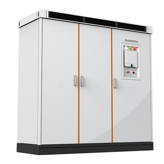
3 Product Description 3.1 Inverter Appearance 3.1.1 Appearance The face and main external components of the inverter are shown in the figure below. Note: The figure takes the standard inverter appearance as an example, and the actual product may differ. Item Name Description... -
Page 16: Lcd Touchscreen
3 Product Description Operation Manual Possible LED combinations and the meaning are listed in the following table: LED status Description All the three indicators are on POWER OPERATION FAULT POWER OPERATION FAULT “POWER” is on POWER OPERATION FAULT POWER OPERATION FAULT “POWER”... -
Page 17: Start/Stop Switch
Operation Manual 3 Product Description 3.1.5 Start/Stop Switch The inverter can only start when the start/stop switch is put in the “start” position. When you put the switch in the "stop" position, the inverter will stop through a stop command sent to the control DSP. 3.2 Communication System 3.2.1 RS485 Communication ... - Page 18 3 Product Description Operation Manual Inverter Fig. 3-4 Ethernet communication of one inverter Multiple inverters communication If there is more than one inverter, the Ethernet switch is required for communication. Insight is used to monitor the communication. Inverter Ethernet Switch Fig.
-
Page 19: Start & Stop
4 Start & Stop 4.1 Starting 4.1.1 Inspection Before Starting After maintenance or troubleshooting, the inverter needs to be started. Check the following items before starting the devices:All connections are done by strictly following the installation manual and circuit diagram. ... -
Page 20: Stopping
4 Start & Stop Operation Manual 4.2 Stopping Inverter stops during normal maintenance and service work or when a fault occurs. 4.2.1 Normal Stopping Proceed as follows to stop the inverter during normal maintenance and service work: Step 1 Stop the inverter through the stop instruction on the LCD. Step 2 Turn the inverter Start/Stop switch to the "STOP"... - Page 21 Operation Manual 4 Start & Stop Cable connection terminal corresponding to the self-powered circuit breaker Q1 of the inverter still carry voltages when the AC side of the inverter is connected to the grid and the following operations are performed: ...
-
Page 22: Operating Mode
5 Operating Mode 5.1 Mode Switching After being energized, the inverter can switch among different modes, as shown in the figure below. Unrecoverable fault Fault removed Stop for repair Set time reached Fault Stop Fault occurs Grid-connection DC current weak conditions met for a long time Powered on... - Page 23 Operation Manual 5 Operating Mode Startup This is the transient process between the Standby mode and the Run mode. Once the Startup mode ends, the inverter starts powering the grid. In this mode, the inverter converts the DC into AC and feeds it to the grid. Inverter tracks the PV arrays’...
- Page 24 5 Operating Mode Operation Manual ON position; reconnect to the grid. The inverter will be restarted automatically when the grid-connected requirements are met on both DC and AC side. Key-stop In Run mode, the inverter will enter into the Key-stop mode by sending stop instruction via the LCD panel if the user needs to conduct maintenance or service work.
-
Page 25: Lcd Menu Operation
6 LCD Menu Operation 6.1 LCD Touchscreen The LCD touch screen, located at the eye-level in the front side of the inverter, is used for the user to view the data and set related parameters. The LCD as shown in the following figure. The user can check or set related data by touching the icons on the LCD display. -
Page 26: Backlight And Screensaver
His-state E-chart His-data His-record Language Chinese English Theme SUNGROW orange Sapphire blue Setting System parameter Run parameter Protect parameter Com parameter 6.3.2 Layout of the submenus The layout of submenus is the same as that shown below except for the default menu. -
Page 27: Entering Password
Operation Manual 6. LCD Menu Operation Item Description Data display or parameter configuration. Three icons in the main screen For convenience, the operations on the menus are referred to as the menu name with quotation marks. For example, the menu will be referred to as "Set-parameter". 6.4 Entering Password The inverter is protected by password. -
Page 28: Language Setting
6. LCD Menu Operation Operation Manual 6.5 Language Setting User can set the language by the following ways: Step 1 Tap "Function" from the default menu. Tap "Language". Step 2 Click to select the language type to be set. Step 3 6.6 Date and Time Setting Step 1 Tap "Function"... -
Page 29: Power Yields Checking
Operation Manual 6. LCD Menu Operation Step 3 Tap the INV1 to enter the real-time data interface of the inversion unit 1. Tap the INV2 to enter the real-time data interface of the inversion unit 2. Step 4 Tap the up and down arrow in the right of the interface to display more information. 6.8 Power Yields Checking The power yields figure can check the total power yields, annual power yields, monthly power yields and daily power yields. - Page 30 6. LCD Menu Operation Operation Manual Step 4 Tap "Year" to enter the annual power yields interface. By taping the arrow marked by A in the figure below to check the annual power yields information of corresponding year. Tap "Month" to enter the monthly power yields interface. By taping the arrow marked by A in Step 5 the figure below to check the monthly power yields information of corresponding month.
-
Page 31: History Information Checking
Operation Manual 6. LCD Menu Operation 6.9 History Information Checking The storage time of the history data is 15-60 minutes (settable). The history data contains the related electrical parameters of the inverter. Proceed as follows to check the history data. Tap "Function"... -
Page 32: Present Fault Information Checking
6. LCD Menu Operation Operation Manual state in different time by clicking the total, event, warning and fault. 6.11 Present Fault Information Checking There may be one or more than one fault occurs to the inverter at the same time which can be viewed through the LCD screen. -
Page 33: Load Default
Operation Manual 6. LCD Menu Operation Step 3 Tap "system parameter" after entering the correct password. DSP_SG1250UD-V11_V1_A Tap the "Error of E-total (kWh)" cell and a keypad appears. Enter the energy compensation Step 4 by tapping the keypad. Tap "Enter" to confirm the setting. Step 5 6.14 Load Default... - Page 34 6. LCD Menu Operation Operation Manual DSP_SG1250UD-V11_V1_A This interface displays the firmware version of IO and DSP Step 4...
-
Page 35: Parameters Of Lcd
7 Parameters of LCD 7.1 Communication Parameters Improper parameter configuration may affect the normal operation of the inverter! Only authorized personnel can configure these parameters. 7.1.1 RS485 Serial Port Parameter Setting There are the standard RS485 communication and Ethernet communication. The user can set the communication address and protocol through the LCD screen when the hardware connection is complete and the inverter is energized. -
Page 36: Running Parameters
7. Parameters of LCD Operation Manual The parameters pertinent to the Ethernet communication can be set. DNS address 1 and DNS address 2 can be set to the default values which are uploaded by the lower computer. Other parameters are assigned by plant staff. Set parameter with the aid of the pop-up keypad. - Page 37 Operation Manual 7. Parameters of LCD Parameter Description The time from the LCD display or upper computer sends stop Stop delay-time (s) command to inverter performs the stop command Active power decline rate from inverter performs stop command Stop slope (%/s) to inverter stops The time from the AC/DC parameters meet the grid-connection T-start-wait (s)
- Page 38 7. Parameters of LCD Operation Manual active power and frequency, f1s For 60Hz grid type, refer to Fig. 7-1Relation curve between 60Hz UF FM end (Hz) active power and frequency, f2s In QU reactive power mode, the method to set the reactive QU operation mode power value Refer to Fig.
- Page 39 Operation Manual 7. Parameters of LCD Q(kvar) Qmax U(V) Qmin Fig. 7-2 Relation curve between reactive power and voltage Setting ranges and default values of the running parameters are described in the following table. Parameter Range Default Stop delay-time (s) 0~600 Stop slope (%/s) 0.1~100...
-
Page 40: Protection Parameter
Improper parameter configuration may affect the normal operation of the inverter! Only authorized personnel can configure these parameters. Should any question or doubt occurs, please contact Sungrow. Please refer to the LCD screen for the specific setting ranges of these parameters. - Page 41 Improper parameter configuration may affect the normal operation of the inverter! Only authorized personnel can configure these parameters. Should any question or doubt occurs, please contact Sungrow. Description of Protection Parameters Descriptions of the protective parameters are shown in the following table.
- Page 42 For directly ground or virtual ground version, set the ground alarm threshold (V) or protection threshold value Setting ranges and default values of the protective parameters are described in the following table. Parameter Range Default SG1250UD: 396~540 Ⅰ_Vgrid-max(V) SG1500UD: 440~600 SG1250UD: 396~540 Ⅱ_Vgrid-max(V) SG1500UD: 440~600 Ⅰ_T-Vhigh trip(ms) 40~600000 2000 Ⅱ_T-Vhigh trip (ms)
- Page 43 Operation Manual 7. Parameters of LCD Parameter Range Default Ⅱ_T-Vlow trip (ms) 40~600000 SG1250UD: 36~324 Recover_Vgrid-min(V) SG1500UD: 40~360 50Hz grid OF protection Ⅰ 50.2~55 50.5 value(Hz) 50Hz grid OF protection Ⅱ 50.2~55 50.5 value(Hz) 60Hz grid OF protection Ⅰ 60.2~65 60.5...
- Page 44 7. Parameters of LCD Operation Manual Parameter Range Default Manualfault restart Enabled/Disabled Disabled voltage ground 20~200 threshold (V) * The parameter default value is set according to the max. PV array output of 1000V. The actual threshold value can be set according to the on-site module configuration with the adjust range of 15~100 kΩ.
-
Page 45: Inverter Functions
8 Inverter Functions 8.1 Perfect Control Strategy The following three control strategies are provided for user to perform control functions and configure relevant parameters. "Remote": The control codes can be sent only by the remote control machine. "Local": The control codes can be sent only by the LCD screen. ... -
Page 46: How To Realize Power Limitation
Improper parameter configuration may affect the normal operation of the inverter! Only authorized personnel can configure these parameters. Should any question or doubt occurs, please contact Sungrow. The user can adjust the active power output through the LCD display: Tap "Function" from the default menu. -
Page 47: Low Voltage Ride Through
Improper parameter configuration may affect the normal operation of the inverter! Only authorized personnel can configure these parameters. Should any question or doubt occurs, please contact Sungrow. 8.4 Low Voltage Ride Through Technical Requirements for Connecting Photovoltaic Power Inverter to Power System requires medium-and-large PV plant should be equipped with Low Voltage Ride Through (LVRT) ability. -
Page 48: High Voltage Ride Through
Note: U indicates grid-connection point voltage, and Upu is the grid-connection point nominal voltage. Sungrow's inverter meets the abovementioned requirements. 8.5 High Voltage Ride Through Technical Requirements for Connecting Photovoltaic Power Inverter to Power System requires PV plant should be able to operate as required within certain voltage range. -
Page 49: Over-Frequency Derating Function
Operation Manual 8. Inverter Functions 8.6 Over-frequency Derating Function When the system frequency deviation is bigger than f1i and the inverter active power is bigger than the startup power Ps, the inverter will adjust the active power output according to the frequency change. P(kW) △P1 (Hz) -
Page 50: Maximum Power Point Tracking
8. Inverter Functions Operation Manual P/Pn L1 = 2%Pn/℃ Nominal value L2 = 10%Pn/℃ T (℃) Fig. 8-5 Inverter temperature derating function Note: Pn is nominal power Ambient temp. T Inverter operation situation T≤-35℃ Inverter needs to start with the aid of auxiliary heater Operate for a long time at 110% of the overload condition -35℃<T≤45℃... -
Page 51: Intelligent Temperature-Control Technology
8.10.2 PID Power Supply Mode Function Setting For inverter with optional PID power function, the enable and disable of this function can only be performed by personnel from Sungrow. Please contact Sungrow if you need to switch this function. Proceed as follows to set the mode if the PID power mode is enabled: Tap "Function"... -
Page 52: Pid Repair
Sungrow's inverter is equipped with insulation resistance monitoring function to detect the system insulation resistance in real time. For optional anti-PID function, the insulation monitoring only monitors the system insulation resistance before the device is connected to the grid. -
Page 53: Grid Self-Establishment And Debugging
On site, the function can be activated based on the distribution load conditions. After the function is enabled, the standby consumption may slightly differ due load differences. Contact the service department of Sungrow to activate this function if necessary. Do not enable the function when the inverter is integrated with a Ethernet switch. - Page 54 8. Inverter Functions Operation Manual The inverter can detect the abnormal voltage and respond quickly. AC over/under-voltage protection When the inverter AC output voltage exceeds the allowable range, the inverter will stop operating, send warning signal and display the fault type on the LCD screen. The inverter can detect the abnormal voltage and respond quickly.
- Page 55 Operation Manual 8. Inverter Functions Internal over-temperature protection The inverter is equipped with high-precision thermal sensor to monitor the internal temperature of the inverter. Once the over-temperature is detected, DSP will help to maintain the safe operation of the inverter by sending instruction to stop the inverter or derate the power output.
-
Page 56: Routine Maintenance
9 Routine Maintenance Due to the effect of ambient temperature, humidity, dust and vibration, the inner components of the inverter will be aging and worn out. To ensure the system safety and maintain the efficiency of the inverter, it is necessary to carry out routine and periodic maintenance. - Page 57 Operation Manual 9. Routine Maintenance following table. Item Method Interval Read out SolarInfo Logger data; Save software Once a month Save running data, parameters and logs to a data disk or a file; Check each parameter setting; ...
-
Page 58: Filter Checking And Cleaning
9. Routine Maintenance Operation Manual Item Method Interval Check the emergency stop button and the LCD Safety function Six months to one stop function; year Simulation shutdown and check the shutdown signal communication signal; Check the warning labels and other markings for damage unclearness. -
Page 59: Replacement Of The Electrical Components
Step 3 Reassemble the filter according to the reverse procedure shown above. Contact Sungrow to order the filter. The user can cut proper filters out of the larger filter. 9.4 Replacement of the Electrical Components The electrical components inside the inverter must be replaced by the same components from the same manufacturer and with the same model number. -
Page 60: Troubleshooting
Respect all safety instructions during troubleshooting. Disconnect all AC and DC Main Switches and external power supplies before troubleshooting. Please contact Sungrow if voltage withstanding test is required during troubleshooting. Should any questions or doubts arise that are not covered by this manual, please contact... -
Page 61: Fault And Troubleshooting Of Led
AC/DC voltage. No LED is on If the LEDs keep off, repair or replace them. Contact Sungrow if the malfunction cannot be removed following these instructions. No power supply to the inverter. First, ensure the power supply and the grid-connection are POWER is off normal. - Page 62 Measure Device internal fault. Wait 3 minutes for device auto-reconnection (if there are no other faults) Contact Sungrow if the fault still exists Remark Stop the inverter if this fault and the hard overcurrent occurs 5 times per day...
- Page 63 System external or internal short-circuit reason Wait 3 minutes for device auto-reconnection (if there are no other faults) Measure Contact Sungrow if the fault still exists Remark Stop the inverter if this fault and the PDP protection occurs 5 times per day Fault...
-
Page 64: Lcd Display Alarm Information And Troubleshooting
Remark Fault Carrier sync fault Possible The parallel connection carrier sync cable is abnormal reason Measure Contact Sungrow to check and maintain the device Remark Fault Parallel operation comm. fault Possible Device internal parallel connection communication cable is abnormal reason... - Page 65 Operation Manual 10. Troubleshooting LVRT Run Alarm Possible When the grid voltage is below the min. LVRT normal voltage and the LVRT function is enabled, this alarm information will be displayed reason The short-time LVRT run alarm will be removed automatically when the grid Measure returns normal if this alarm is caused by grid fault.
- Page 66 Contactor contact flt Possible The contact of the inverter internal contactor is in poor contact reason Measure Contact Sungrow Remark Before device stops, inverter can operate in grid-connection normally Alarm Meter-com-flt This alarm occurs if the communication of inverter's DC and/or AC meter and the Possible device is poor.
-
Page 67: Other Faults
PC communication module on the LCD display Remark The monitor disk might be incompatible with the antivirus software and thus cannot be installed correctly. You are recommended to disable the antivirus software and then install the monitor software. If the fault still occurs, please contact Sungrow... - Page 68 Appendix 11.1 Technical Parameters Item SG1250UD SG1500UD Input (DC) Max. input voltage 1100V 1100V Start-up voltage 540V 600V Min. operating voltage 520V 580V MPP voltage range 520~1000V 580~1000V MPP voltage range for full 520~850V 580~850V load No. of MPPT No. of DC inputs 16 (12~20 optional) Max.
- Page 69 Operation Manual 11 Appendix Protection DC overvoltage protection reverse connection protection DC short-circuit protection Grid monitoring GFDI Insulation monitoring Over-temperature protection Other functions PID protection and recovery Optional SVG function Night sleep mode AC parallel connection Soft start and stop Auto switch between power Optional supply modes...
- Page 70 Unforeseen calamity or force majeure The use of supplied software produced by Sungrow Power Supply Co., Ltd. is subject to the following conditions: Sungrow Power Supply Co., Ltd. assumes no liability for direct or indirect damages arising from the use of software.
Need help?
Do you have a question about the SG1250UD and is the answer not in the manual?
Questions and answers