Sungrow SG125HX User Manual
Pv grid-connected inverter
Hide thumbs
Also See for SG125HX:
- Quick installation manual (9 pages) ,
- User manual (124 pages) ,
- User manual (109 pages)

Related Manuals for Sungrow SG125HX


Summary of Contents for Sungrow SG125HX
- Page 1 PV Grid-Connected Inverter User Manual SG125HX WWW.SUNGROWPOWER.COM SG125HX-UEN-Ver14-202105...
-
Page 3: All Rights Reserved
It is prohibited to use data contained in firmware or software developed by • SUNGROW, in part or in full, for commercial purposes by any means. It is prohibited to perform reverse engineering, cracking, or any other operations that •... -
Page 4: About This Manual
V V a a l l i i d d i i t t y y This manual is valid for the following inverter models: SG125HX • They will be referred to as "inverter" hereinafter unless otherwise specified. T T a a r r g g e e t t G G r r o o u u p p... - Page 5 Indicates a hazard with a low level of risk that, if not avoided, could result in minor or moderate injury. Indicates a situation that, if not avoided, could result in equipment or property damage. Indicates additional information, emphasized contents or tips that may be helpful, e.g.
-
Page 7: Table Of Contents
C C o o n n t t e e n n t t s s All Rights Reserved .....................I About This Manual .....................II 1 Safety ......................1 1.1 PV Panels..................... 1 1.2 Utility Grid ....................1 1.3 Inverter ......................2 2 Product Description .................. - Page 8 5 Electrical Connection ................23 5.1 Safety Instructions..................23 5.2 Terminal Description................... 23 5.3 Electrical Connection Overview ..............24 5.4 Crimp OT/DT terminal................. 28 5.5 Additional Grounding Connection ............... 29 5.5.1 Additional Grounding Requirements..........29 5.5.2 Connection Procedure ..............29 5.6 AC Cable Connection .................
- Page 9 7.4.1 Requirements ................... 54 7.4.2 Login Procedure ................54 7.5 Home page ....................56 7.6 Run Information ..................58 7.7 Records ..................... 60 7.8 More ......................62 7.8.1 System Parameters ................62 7.8.2 Operation Parameters ..............63 7.8.3 Power Regulation Parameters............64 7.8.4 Communication Parameters .............
-
Page 11: Safety
The safety instructions in this manual cannot cover all the precautions that should be followed. Perform operations considering actual onsite conditions. SUNGROW shall not be held liable for any damage caused by violation of the safety instructions in this manual. -
Page 12: Inverter
1 Safety User Manual All electrical connections must be in accordance with local and national standards. Only with the permission of the local utility grid company, the inverter can be connected to the utility grid. 1.3 Inverter Danger to life from electric shocks due to live voltage Do not open the enclosure at any time. - Page 13 User Manual 1 Safety Only qualified personnel can perform the country setting. Unauthorized alteration may cause a breach of the type-certificate marking. Risk of inverter damage due to electrostatic discharge (ESD)! By touching the electronic components, you may damage the inverter. For inverter handling, be sure to: avoid any unnecessary touching;...
-
Page 14: Product Description
N N o o t t e e Monocrystalline silicon, polycrystalline silicon and thin-film PV strings without grounding. Inverter SG125HX Grid connection Includes devices such as AC circuit breaker, SPD, metering cabinet device. Boost the low voltage from the inverter to grid-compatible Transformer medium voltage. -
Page 15: Product Introduction
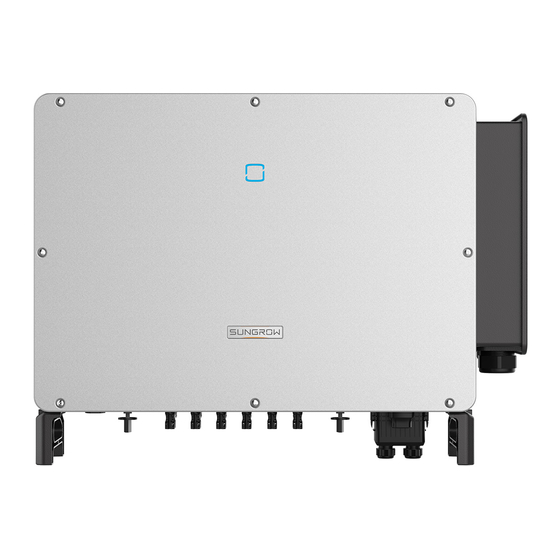
User Manual 2 Product Description Make sure the inverter is applied to an IT system before enabling the Anti-PID function. 2.2 Product Introduction M M o o d d e e l l D D e e s s c c r r i i p p t t i i o o n n The model description is as follows : A A p p p p e e a a r r a a n n c c e e The following figure shows the dimensions of the inverter. - Page 16 2 Product Description User Manual f f i i g g u u r r e e 2 2 - - 2 2 Inverter Appearance D D e e s s c c r r i i p p t t i i o o n n N N o o .
-
Page 17: Symbols On The Product
User Manual 2 Product Description f f i i g g u u r r e e 2 2 - - 3 3 Dimensions of the Inverter(in mm) 2.3 Symbols on the Product S S y y m m b b o o l l E E x x p p l l a a n n a a t t i i o o n n Do not dispose of the inverter together with household waste. -
Page 18: Circuit Diagram
2 Product Description User Manual table 2-1 State description of the LED indicator L L E E D D c c o o l l o o r r S S t t a a t t e e D D e e f f i i n n i i t t i i o o n n The device is connected to the grid and operating normally. -
Page 19: Function Description
User Manual 2 Product Description 2.6 Function Description The inverter is equipped with the following functions: C C o o n n v v e e r r s s i i o o n n F F u u n n c c t t i i o o n n The inverter converts the DC current into grid-compatible AC current and feeds the AC current into the grid. - Page 20 2 Product Description User Manual Anti-PID function • When the inverter is running, the PID module rises the potential between the negative pole of the PV array and the ground to a positive value, to suppress the PID effect. Make sure the inverter is applied to an IT system before enabling the anti-PID function.
- Page 21 User Manual 2 Product Description A A F F C C I I F F u u n n c c t t i i o o n n ( ( O O p p t t i i o o n n a a l l ) ) AFCI activation •...
-
Page 22: Unpacking And Storage
Check the inner contents for damage after unpacking. • Contact SUNGROW or the transport company in case of any damage or incompleteness, and provide photos to facilitate services. Do not dispose of the original packing case. It is recommended to store the device in the original packing case when the device is decommissioned. -
Page 23: Mechanical Mounting
Mechanical Mounting 4.1 Safety during Mounting Make sure there is no electrical connection before installation. In order to avoid electric shock or other injury, make sure that holes will not be drilled over any electricity or plumbing installations. Risk of injury due to improper handling Always follow the instructions when moving and positioning the inverter. -
Page 24: Environment Requirements
4 Mechanical Mounting User Manual 4.2.1 Environment Requirements The installation environment must be free of inflammable or explosive materials. • The location should be not accessible to children. • The ambient temperature and relative humidity must meet the following • requirements. -
Page 25: Clearance Requirements
User Manual 4 Mechanical Mounting 4.2.4 Clearance Requirements Reserve enough clearance around the inverter to ensure sufficient space for heat dissipation. In case of multiple inverters, reserve specific clearance between the inverters. Install the inverter at an appropriate height for ease of viewing LED indicator and operating switch(es). - Page 26 4 Mechanical Mounting User Manual Insulated shoes Utility knife Slotted screwdriver Phillips screwdriver (M4, M6, M8) (M2, M6) Hammer drill Pliers Marker Level (φ12, φ14) Rubber mallet Wrench Wrist strap Socket wrench set (16mm) (13 mm, 16 mm) Wire cutter Wire stripper Hydraulic plier Heat gun...
-
Page 27: Moving The Inverter
User Manual 4 Mechanical Mounting Vacuum cleaner 4.4 Moving the Inverter Before installation, remove the inverter from the packing case and move it to the installation site. The inverter can be moved manually or via a hoist. 4.4.1 Manual Transport Lift and move the inverter to the destination by using the side handles and bottom handles. -
Page 28: Hoisting Transport
4 Mechanical Mounting User Manual 4.4.2 Hoisting Transport step 1 Release the sealing screws on the mounting ears and store them properly. Anchor two M12 thread lifting rings to the hangers of the inverter. step 2 Lead the sling through the two lifting rings and fasten the tie-down strap. step 3 Hoist the inverter, and stop to check for safety when the inverter is 100mm above the ground. -
Page 29: Installing The Mounting-Bracket
User Manual 4 Mechanical Mounting Keep the inverter balanced throughout the hoisting process and avoid collisions with walls or other objects. Stop hoisting in the event of severe weather, such as heavy rain, thick fog, or strong wind. The lifting rings and the sling are not within the delivery scope. - - - - E E n n d d 4.5 Installing the mounting-bracket Inverter is installed on the wall and bracket by means of mounting bracket. -
Page 30: Wall-Mounted Installation
4 Mechanical Mounting User Manual step 3 Secure the mounting-bracket with bolts. C C o o m m p p o o n n e e n n t t s s D D e e s s c c r r i i p p t t i i o o n n N N o o . -
Page 31: Installing The Inverter
User Manual 4 Mechanical Mounting step 4 Fix the mounting-bracket with the expansion bolts. C C o o m m p p o o n n e e n n t t s s D D e e s s c c r r i i p p t t i i o o n n N N o o . - Page 32 4 Mechanical Mounting User Manual - - - - E E n n d d...
-
Page 33: Electrical Connection
Electrical Connection 5.1 Safety Instructions Prior to any electrical connections, keep in mind that the inverter has dual power supplies. It is mandatory for the qualified personnel to wear personal protective equipments (PPE) during the electrical work. Danger to life due to a high voltage inside the inverter! The PV string will generate lethal high voltage when exposed to sunlight. -
Page 34: Electrical Connection Overview
5 Electrical Connection User Manual f f i i g g u u r r e e 5 5 - - 1 1 Terminal Description * The image shown here is for reference only. The actual product received may differ. I I t t e e m m T T e e r r m m i i n n a a l l M M a a r r k k... - Page 35 User Manual 5 Electrical Connection D D e e s s i i g g n n a a t t i i o o n n I I t t e e m m PV string Inverter Grid Monitoring device AC circuit breaker table 5-1 Cable Requirements S S p p e e c c i i f f i i c c a a t t i i o o n n...
- Page 36 (1) A copper to aluminum adapter terminal is required when an aluminum cable is used. For details, refer to " Aluminium Cable Requirements". (2) If case of four single-core cables, an spare AC sealing plate accessory is required. To purchase the AC sealing plate accessory, contact SUNGROW.
- Page 37 User Manual 5 Electrical Connection f f i i g g u u r r e e 5 5 - - 2 2 Spare AC Sealing Plate table 5-2 PE Wire Requirements P P E E W W i i r r e e C C r r o o s s s s N N o o t t e e S S e e c c t t i i o o n n The specifications are valid only when the phase wire and PE...
-
Page 38: Crimp Ot/Dt Terminal
5 Electrical Connection User Manual 5.4 Crimp OT/DT terminal C C r r i i m m p p O O T T / / D D T T t t e e r r m m i i n n a a l l 1. -
Page 39: Additional Grounding Connection
The ground connection of this additional grounding terminal cannot replace • the connection of the PE terminal of the AC cable. Make sure those terminals are both grounded reliably. SUNGROW shall not be held liable for any damage caused by the violation. 5.5.1 Additional Grounding Requirements All non-current carrying metal parts and device enclosures in the PV power system should be grounded, for example, mounts of PV modules and the inverter enclosure. -
Page 40: Ac Cable Connection
M M u u l l t t i i p p l l e e I I n n v v e e r r t t e e r r s s i i n n P P a a r r a a l l l l e e l l C C o o n n n n e e c c t t i i o o n n If multiple inverters are connected in parallel to the grid, ensure that the total number of parallel inverters does not exceed 30. Otherwise, please contact SUNGROW for technical scheme. - Page 41 • transformer. The maximum AC current of all inverters connected in parallel must be taken into account. If more than 30 inverters are connected to the grid, contact SUNGROW. The transformer must be protected against overloading and short circuit. •...
-
Page 42: Requirements For Ot/Dt Terminal
5 Electrical Connection User Manual 5.6.2 Requirements for OT/DT Terminal OT/DT terminals (not included in the delivery scope) are required for fixing AC cables to the terminal block. Purchase the OT/DT terminals according to the following requirements. O O T T / / D D T T T T e e r r m m i i n n a a l l s s o o f f P P h h a a s s e e W W i i r r e e Specification: M10;... - Page 43 User Manual 5 Electrical Connection step 3 Loosen the screws of the bottom sealing plate and take out the bottom sealing plate. step 4 Loosen the swivel nut of the AC waterproof connector and select a seal according to the cable outer diameter, remove the inner sealing ring if the cable diameter is larger than 40mm.
- Page 44 5 Electrical Connection User Manual step 5 Install the cables and reinstall the bottom sealing plate. step 6 Open the protection cover. step 7 Strip the protection layer and insulation layer by specific length, as described in the figure below. step 8 Make the cable and crimp OT/DT terminal.
- Page 45 User Manual 5 Electrical Connection Ensure that the depth L of the socket used is not less than 28mm.
- Page 46 5 Electrical Connection User Manual If the PE cable is an independent single-core cable, it should be inserted into the cabinet through the standby grounding terminal. step 10Close the protection cover. step 11Close the wiring compartment and tighten the two screws on its front cover with supplied Allen wrench.
-
Page 47: Dc Cable Connection
User Manual 5 Electrical Connection - - - - E E n n d d 5.7 DC Cable Connection Danger of electric shock! The PV array will generate lethal high voltage once exposed to sunlight. Make sure the PV array is well insulated to ground before connecting it to the inverter. -
Page 48: Assembling The Pv Connectors
Do not connect the AC circuit breaker before finishing electrical connection. • SUNGROW provides corresponding PV connectors in the scope of delivery for quick connection of PV inputs. To ensure IP66 protection, use only the supplied connector or the connector with the same ingress of protection. -
Page 49: Installing The Pv Connector
User Manual 5 Electrical Connection step 2 Assemble the cable ends with the crimping pliers. 1: Positive crimp contact 2:Negative crimp contact step 3 Lead the cable through cable gland, and insert the crimp contact into the insulator until it snaps into place. - Page 50 5 Electrical Connection User Manual step 2 Check the cable connection of the PV string for polarity correctness and ensure that the open circuit voltage in any case does not exceed the inverter input limit of 1,500V. step 3 Connect the PV connectors to corresponding terminals until there is an audible click.
-
Page 51: Communication Junction Box
Arc or contactor over-temperature may occur if the PV connectors are not • firmly connected in place, and SUNGROW shall not be held liable for any damage caused due to this operation. step 4 Follow the foregoing steps to connect PV connectors of other PV strings. -
Page 52: Communication Wiring Board
5 Electrical Connection User Manual 5.9 Communication Wiring Board The communication board of the inverter includes two layers. The upper layer communication board mainly includes RS485 communication interfaces while the lower layer communication board mainly includes DI/DO interface. 5.10 RS485 Connection 5.10.1 Interface Description As shown in the Figure below, the inverter is equipped with three RS485 communication interfaces and one dip switch. -
Page 53: Rs485 Communication System
User Manual 5 Electrical Connection The RS485-1 crimp and the RJ45 interface can be applied to applications where multiple inverters communicate in a daisy-chain form. A 120Ω resistor can be connected in parallel between RS485-1 A/B pins by configuring the dip switch. RS485-1 crimp interface and RJ45 interface serve as the same function with different wiring manner. - Page 54 5 Electrical Connection User Manual f f i i g g u u r r e e 5 5 - - 6 6 Multi-inverter Connection When more than 15 inverters are connected to the same daisy chain, in order to ensure the communication quality, the Logger at the first end of the daisy chain needs to be equipped with a terminal resistor of 120Ω, the inverter at the last end needs to be equipped with a RS485-dip switch (SW1), and the shielding layer of the communication...
-
Page 55: Connection Procedure(Terminal Block)
User Manual 5 Electrical Connection 5.10.3 Connection Procedure(Terminal Block) RS485 communication cables should be shielded twisted pair cables or shielded twisted pair Ethernet cables. There are three communication terminals, and the silkscreen marks are COM1/COM2/COM3. Please choose according to the actual situation. step 1 Remove the communication junction box, see"... -
Page 56: Connection Procedure (Rj45 Ethernet Port)
5 Electrical Connection User Manual step 5 Insert the terminal base into the corresponding terminal. table 5-4 Terminal definition N N o o D D e e f f i i n n i i t t i i o o n n RS485 A+ RS485 A+ RS485 B-... - Page 57 User Manual 5 Electrical Connection O O u u t t e e r r D D i i a a m m e e t t e e r r D D ( ( m m m m ) ) S S e e a a l l 4.5~6 6~12...
-
Page 58: Plc Communication Connection
5.11 PLC Communication Connection With a PLC communication module built inside, the inverter can communicate with the COM100A provided by SUNGROW. For specific wiring method, refer to the COM100A user manual. In case of PLC communication, both the multi-core cable and the single- •... - Page 59 User Manual 5 Electrical Connection D D O O t t e e r r m m i i n n a a l l ( ( f f a a u u l l t t o o u u t t p p u u t t d d r r y y c c o o n n t t a a c c t t ) ) : : The relay can be set to output fault alarms, and user can configure it to be a normally open contact (COM &...
-
Page 60: Wiring Procedure
Block)". 5.13 Communication Module Connection (optional) Connect the communication module produced by SUNGROW, such as Eye M4(WiFi) to the communication accessory port. After successful connection, information such as power generation and running state of the inverter can be viewed via the APP on the phone. - Page 61 User Manual 5 Electrical Connection The communication module and the RS485 communication are not available at the same time. Otherwise, communication failure or other problems can be caused. For details on module installation and configuration, refer to the manual delivered together with the module.
-
Page 62: Commissioning
Commissioning 6.1 Inspection before Commissioning Check the following items before starting the inverter: All the installation sites are convenient for operation, maintenance and service. • All devices are firmly installed. • Space for ventilation is sufficient for one inverter or multiple inverters. •... -
Page 63: Isolarcloud App
iSolarCloud App 7.1 Brief Introduction The iSolarCloud App can establish communication connection to the inverter via the Bluetooth, thereby achieving near-end maintenance on the inverter. Users can use the App to view basic information, alarms, and events, set parameters, or download logs, etc. -
Page 64: Function Overview
7 iSolarCloud App User Manual 7.3 Function Overview The App provides parameter viewing and setting functions, as shown in the following figure. f f i i g g u u r r e e 7 7 - - 1 1 App function tree map 7.4 Login 7.4.1 Requirements The following requirements should be met:... - Page 65 To set inverter parameters related to grid protection and grid support, contact SUNGROW to obtain the advanced account and corresponding password. step 4 If the inverter is not initialized, you will enter the quick setting screen of initializing protection parameter.
-
Page 66: Home Page
7 iSolarCloud App User Manual f f i i g g u u r r e e 7 7 - - 4 4 Initialization Protection Parameter Reset the protection parameters if the country setting is incorrect. Otherwise, a fault may occur. In the European region, such as Netherlands, Sweden, and Denmark, whose grid code complies with EN50549, select the parameter EN50549_1 (LV grid- connection) or EN50549_2 (MV grid-connection). - Page 67 User Manual 7 iSolarCloud App f f i i g g u u r r e e 7 7 - - 5 5 Home Page table 7-1 Home Page Description D D e e s s i i g g n n a a t t i i o o n n D D e e s s c c r r i i p p t t i i o o n n N N o o .
-
Page 68: Run Information
7 iSolarCloud App User Manual table 7-2 Description of Inverter State D D e e s s c c r r i i p p t t i i o o n n S S t t a a t t e e After being energized, the inverter tracks the PV arrays’... - Page 69 User Manual 7 iSolarCloud App table 7-4 Run Information C C l l a a s s s s i i f f i i c c a a - - D D e e s s c c r r i i p p t t i i o o n n P P a a r r a a m m e e t t e e r r t t i i o o n n String n Voltage...
-
Page 70: Records
7 iSolarCloud App User Manual C C l l a a s s s s i i f f i i c c a a - - D D e e s s c c r r i i p p t t i i o o n n P P a a r r a a m m e e t t e e r r t t i i o o n n Phase B Current... - Page 71 User Manual 7 iSolarCloud App f f i i g g u u r r e e 7 7 - - 8 8 Detailed Fault Alarm Information Y Y i i e e l l d d R R e e c c o o r r d d Tap Y Y i i e e l l d d R R e e c c o o r r d d to enter the screen showing daily power generation , as shown in the following figure.
-
Page 72: More
7 iSolarCloud App User Manual D D e e s s c c r r i i p p t t i i o o n n P P a a r r a a m m e e t t e e r r Monthly energy Shows the power output every month in a year. -
Page 73: Operation Parameters
User Manual 7 iSolarCloud App f f i i g g u u r r e e 7 7 - - 1 1 1 1 System Parameters B B o o o o t t / / S S h h u u t t d d o o w w n n Tap B B o o o o t t / / S S h h u u t t d d o o w w n n to send the boot/shutdown instruction to the inverter. -
Page 74: Power Regulation Parameters
7 iSolarCloud App User Manual f f i i g g u u r r e e 7 7 - - 1 1 3 3 PID Setting table 7-6 PID Parameter Description D D e e s s c c r r i i p p t t i i o o n n P P a a r r a a m m e e t t e e r r Set enabling/disabling of the PID night recovery function. - Page 75 User Manual 7 iSolarCloud App f f i i g g u u r r e e 7 7 - - 1 1 5 5 Active Power Regulation table 7-7 Active Power Regulation D D e e f f i i n n i i t t i i o o n n / / S S e e t t t t i i n n g g R R a a n n g g e e P P a a r r a a m m e e t t e e r r D D e e s s c c r r i i p p t t i i o o n n...
- Page 76 7 iSolarCloud App User Manual D D e e f f i i n n i i t t i i o o n n / / S S e e t t t t i i n n g g R R a a n n g g e e P P a a r r a a m m e e t t e e r r D D e e s s c c r r i i p p t t i i o o n n...
- Page 77 User Manual 7 iSolarCloud App D D e e f f i i n n i i t t i i o o n n / / S S e e t t t t i i n n g g R R a a n n g g e e P P a a r r a a m m e e t t e e r r D D e e s s c c r r i i p p t t i i o o n n...
- Page 78 7 iSolarCloud App User Manual D D e e f f i i n n i i t t i i o o n n / / S S e e t t t t i i n n g g R R a a n n g g e e P P a a r r a a m m e e t t e e r r D D e e s s c c r r i i p p t t i i o o n n...
-
Page 79: Communication Parameters
User Manual 7 iSolarCloud App D D e e f f i i n n i i t t i i o o n n / / S S e e t t t t i i n n g g R R a a n n g g e e P P a a r r a a m m e e t t e e r r D D e e s s c c r r i i p p t t i i o o n n... - Page 80 7 iSolarCloud App User Manual f f i i g g u u r r e e 7 7 - - 2 2 0 0 Firmware Download step 3 Select the firmware from the file list and download. Tap D D o o w w n n l l o o a a d d e e d d to view successfully downloaded firmware package.
-
Page 81: Password Changing
User Manual 7 iSolarCloud App 7.8.6 Password Changing Tap M M o o d d i i f f y y P P a a s s s s w w o o r r d d to enter the modify password screen, as shown in the following figure. -
Page 82: System Decommissioning
System Decommissioning 8.1 Disconnecting the Inverter For maintenance or other service work, the inverter must be switched off. Proceed as follows to disconnect the inverter from the AC and DC power sources. Lethal voltages or damage to the inverter will follow if otherwise. step 1 Disconnect the external AC circuit breaker and secure it against reconnection. -
Page 83: Disposal Of The Inverter
User Manual 8 System Decommissioning 8.3 Disposal of the Inverter Users take the responsibility for the disposal of the inverter. Some parts and devices of the inverter, such as the capacitors, may cause environmental pollution. Do not dispose of the product together with household waste but in accordance with the disposal regulations for electronic waste applicable at the installation site. -
Page 84: Troubleshooting And Maintenance
App. 3. Check whether the cross-sectional area of the AC cable meets the requirement. 4. If the fault is not caused by the foregoing reasons and still exists, contact SUNGROW. Grid transient Generally, the inverter will be reconnected overvoltage, to the grid after the grid returns to normal. - Page 85 3. Check whether the AC cable is firmly connected in place. 4. If the fault is not caused by the foregoing reasons and still exists, contact SUNGROW. Generally, the inverter will be reconnected to the grid after the grid returns to normal. If the fault occurs repeatedly: 1.
- Page 86 SUNGROW. Wait for the inverter to return to normal. Disconnect the AC and DC switches, and Device anomaly reconnect the AC and DC switches 15 minutes later to restart the inverter. If the fault still exists, contact SUNGROW.
- Page 87 AC and DC cables are well insulated. 3. If the fault is not caused by the foregoing reasons and still exists, contact SUNGROW. Generally, the inverter will be reconnected to the grid after the grid returns to normal. If...
- Page 88 Wait for the inverter to return to normal. power is excessively large and out of the If the fault still exists, contact SUNGROW. normal operation range of the inverter. Generally, the inverter will be reconnected to the grid after the grid returns to normal. If the fault occurs repeatedly: 1.
- Page 89 Device anomaly reconnect the AC and DC switches 15 minutes later to restart the inverter. If the fault still exists, contact SUNGROW. Wait for the inverter to return to normal. If the fault occurs repeatedly: 1. Check whether the ISO resistance...
- Page 90 Disconnect the AC and DC switches, and Device anomaly reconnect the AC and DC switches 15 040-042 minutes later to restart the inverter. If the fault still exists, contact SUNGROW. Low ambient temperature, the ambient temperature is Stop and disconnect the inverter. Restart...
- Page 91 2. Check if the xth DC fuse is damaged. If so, replace the fuse. 3.If the fault is not caused by the foregoing reasons and still exists, contact SUNGROW. *The code 078 to code 081 are corresponding to PV 1 to PV 4 respectively.
- Page 92 Restart the inverter or clear the fault through Protection self-check the App. failure on grid side If the fault still exists, contact SUNGROW. 1. Check whether the AC cable is correctly connected. 2. Check whether the insulation between Grounding cable fault the ground cable and the live wire is normal.
- Page 93 String x reverse 448~471 2. If the fault is not caused by the foregoing connection fault reasons and still exists, contact SUNGROW. *The code 448 to code 471 are corresponding to string 1 to string 24 respectively. 1. Check whether the corresponding string is of reverse polarity.
- Page 94 String x output current 548-563 3. If the fault is not caused by the foregoing anomaly reasons and still exists, contact SUNGROW. *The code 548 to code 563 are corresponding to string 1 to string 16 respectively. 1. Check whether the corresponding string is of reverse polarity.
-
Page 95: Maintenance
As the inverter contains no component parts that can be maintained, never arbitrarily replace any internal components. For any maintenance need, please contact SUNGROW. Otherwise, SUNGROW shall not be held liable for any damage caused. Servicing of the device in accordance with the manual should never be undertaken in the absence of proper tools, test equipments or the latest revision of the manual which has been clearly and thoroughly understood. -
Page 96: Routine Maintenance
9 Troubleshooting and Maintenance User Manual 9.2.2 Routine Maintenance I I t t e e m m M M e e t t h h o o d d P P e e r r i i o o d d Six months to a year Check the temperature and dust of System clean... - Page 97 User Manual 9 Troubleshooting and Maintenance step 3 Press the tab of the latch hook, unplug the cable connection joint outwards, and loosen the screw on the fan holder. step 4 Pull out the fan module, clean the fans with soft brush or vacuum cleaner, and replace them when necessary.
-
Page 98: Appendix
10 Appendix 10.1 Technical Data S S G G 1 1 2 2 5 5 H H X X P P a a r r a a m m e e t t e e r r s s I I n n p p u u t t ( ( D D C C ) ) Max. -
Page 99: Wring Distance Of Di Dry Contact
User Manual 10 Appendix S S G G 1 1 2 2 5 5 H H X X P P a a r r a a m m e e t t e e r r s s P P r r o o t t e e c c t t i i o o n n DC reverse connection protection AC short-circuit protection... - Page 100 10 Appendix User Manual refers to the cable length in one direction between the DI dry contact terminal of the inverter and the corresponding terminal of the (k-1) inverter. table 10-1 Correspondence between number of inverters and maximum wiring distance M M a a x x i i m m u u m m w w i i r r i i n n g g d d i i s s t t a a n n c c e e ( ( u u n n i i t t : : m m ) ) N N u u m m b b e e r r o o f f i i n n v v e e r r t t e e r r...
-
Page 101: Quality Assurance
E E x x c c l l u u s s i i o o n n o o f f L L i i a a b b i i l l i i t t y y In the following circumstances, SUNGROW has the right to refuse to honor the quality guarantee: The free warranty period for the whole machine/components has expired. - Page 102 A A u u s s t t r r a a l l i i a a C C h h i i n n a a ( ( H H Q Q ) ) Sungrow Power Supply Co., Ltd Sungrow Australia Group Pty. Ltd.
- Page 103 User Manual 10 Appendix T T h h a a i i l l a a n n d d S S p p a a i i n n Sungrow Thailand Co., Ltd. Sungrow Ibérica S.A.U. Bangkok Mutilva +66 891246053 +34 948 05 22 04 service@th.sungrowpower.com...