Sign In
Upload
Download
Table of Contents
Contents
Add to my manuals
Delete from my manuals
Share
URL of this page:
HTML Link:
Bookmark this page
Add
Manual will be automatically added to "My Manuals"
Print this page
×
Bookmark added
×
Added to my manuals
Manuals
Brands
Sungrow Manuals
Inverter
SG10KTL
User manual
Sungrow SG10KTL User Manual
Pv grid-connected inverter
Hide thumbs
1
2
3
4
5
Table Of Contents
6
7
8
9
10
11
12
13
14
15
16
17
18
19
20
21
22
23
24
25
26
27
28
29
30
31
32
33
34
35
36
37
38
39
40
41
42
43
44
45
46
47
48
49
50
51
52
53
54
55
56
57
58
59
60
61
62
63
64
65
66
67
68
69
70
71
72
73
74
75
76
77
78
79
80
81
82
83
84
85
86
87
88
89
90
91
92
93
94
95
96
97
98
page
of
98
Go
/
98
Contents
Table of Contents
Troubleshooting
Bookmarks
Table of Contents
About this Manual
Table of Contents
1 Safety Instructions
2 Product Introduction
Intended Usage
Product Description
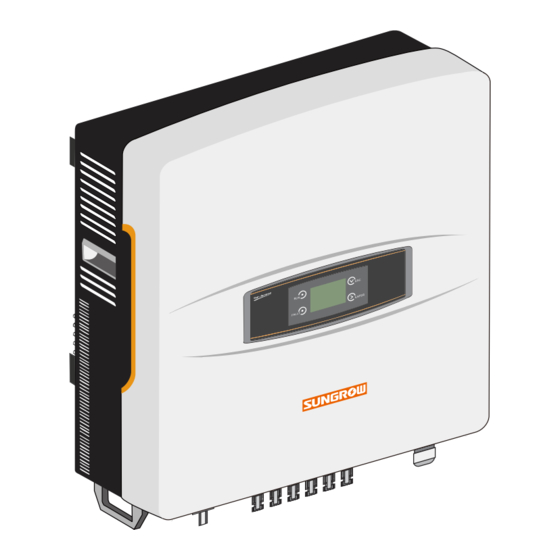
Product Appearance
Dimensions and Weight of Inverter
LCD Display Panel
DC Switch
Technical Description
Principle Description
Functions Description
Derating
3 Installation Flow
4 Unpacking and Storage
Unpacking and Inspection
Identifying Inverter
Delivery Contents
Storage of Inverter
5 Installing Inverter Onto Wall
Selecting Installation Location
Moving Inverter to Installation Site
Mounting the Inverter
Installing the Inverter on Concrete Wall
Installing the Inverter on Metal Frame
6 Electrical Connection
Terminals Description
Simplified Electrical Connection Diagram
Connecting Inverter to AC Grid
AC Side Requirements
Connecting Inverter to AC Grid
Connecting Inverter to PV Arrays
PV Inputs Configuration
Assembling DC Cable to Connector
Wiring Procedures
Grounding the Inverter
Grounding System Overview
Second Protective Earth Terminals
Communication Connection
Communication Overview
Communication System
RS485 Communication Connection
7 Commissioning
Inspection before Commissioning
Commissioning Procedure
8 Disconnecting, Dismantling and Disposing the Inverter
Disconnecting the Inverter
Dismantling the Inverter
Disposing the Inverter
9 Troubleshooting and Maintenance
Troubleshooting
Troubleshooting of LED Indicator
Troubleshooting of Faults in LCD Screen
Maintenance
Routine Maintenance
Maintenance Instruction
Contact Sungrow Service
10 Operation of LCD Display Panel
Description of Button Function
Inverter Menu Structure
Main Screen
Adjust Contrast
Detailed Running Information
History Records
Running Information Records
Fault Records
Start and Stop Inverter
Input Parameter Settings Password
System Parameters Setting
Language Setting
Time Setting
Energy Deviation Adjustment
Load Default
Firmware Version
Running Parameter Setting
Main Screen of Run-Param
Reactive Power Regulation
Save P/Q-Set
Protective Parameters Setting
Communication Parameters Setting
PV Configuration Mode Setting
Special Settings for Italy
Over-Frequency Derating Setting for Italy
Reactive Power Regulation for Italy
Protective Parameters Setting for Italy
11 Appendix
Technical Data
Terminals and Cables
Exclusion of Liability
About Us
Advertisement
Quick Links
1
Communication Connection
2
Troubleshooting
3
Technical Data
Download this manual
User Manual
SG10KTL/SG12KTL/
SG15KTL/SG20KTL
PV Grid-Connected Inverter
SG10_12_15_20KTLV41-UEN-Ver30-201412 Version: 3.0
Table of
Contents
Previous
Page
Next
Page
1
2
3
4
5
Advertisement
Table of Contents
Troubleshooting
Troubleshooting and Maintenance
61
Troubleshooting of Faults in LCD Screen
62
Need help?
Do you have a question about the SG10KTL and is the answer not in the manual?
Ask a question
Questions and answers
Related Manuals for Sungrow SG10KTL
Inverter Sungrow SG10KTL-EC User Manual
Pv grid-connected inverter (136 pages)
Inverter Sungrow SG5KTL-MT User Manual
Pv grid-connected inverter (80 pages)
Inverter Sungrow SG10KTL-M User Manual
Pv grid-connected inverter (90 pages)
Inverter Sungrow SG10KTL-M User Manual
Pv grid-connected inverter (89 pages)
Inverter Sungrow SG5KTL-MT User Manual
Pv grid-connected inverter (100 pages)
Inverter Sungrow SG5KTL-MT User Manual
Pv grid-connected inverter (112 pages)
Inverter Sungrow SG15KTL-M User Manual
Pv grid-connected inverter (109 pages)
Inverter Sungrow SG33KTL-M Installation Manual
Solar on grid string inverter (6 pages)
Inverter Sungrow SG100KU Installation Manual
Pv grid-connected inverter (70 pages)
Inverter Sungrow SG15KTL-M User Manual
Pv grid-connected inverter (101 pages)
Inverter Sungrow SG5KTL-MT Quick Manual
3-phase residential and commercial inverters (16 pages)
Inverter Sungrow SG3.0RT User Manual
3-phase pv grid-connected inverter (116 pages)
Inverter Sungrow SG5.0RT User Manual
3-phase pv grid-connected inverter (105 pages)
Inverter Sungrow SG5.0RT-P2 User Manual
3-phase pv grid-connected inverter (153 pages)
Inverter Sungrow SG8.0RS User Manual
1-phase pv grid-connected inverter (123 pages)
Inverter Sungrow SG5KTL-MT Quick Manual
3-phase pv inverters (5-20kw) commissioning with logger1000 (16 pages)
This manual is also suitable for:
Sg15ktl
Sg12ktl
Sg20ktl
Table of Contents
Save PDF
Print
Rename the bookmark
Delete bookmark?
Delete from my manuals?
Login
Sign In
OR
Sign in with Facebook
Sign in with Google
Upload manual
Upload from disk
Upload from URL


Need help?
Do you have a question about the SG10KTL and is the answer not in the manual?
Questions and answers