Sungrow SG125HV User Manual
Pv grid-connected inverter
Hide thumbs
Also See for SG125HV:
- User manual (122 pages) ,
- Quick installation manual (16 pages) ,
- Installation manual (6 pages)

Related Manuals for Sungrow SG125HV


Summary of Contents for Sungrow SG125HV
- Page 1 User Manual SG125HV PV Grid-connected Inverter SG125HV-UEN-Ver11-201707 Version: 1.1...
- Page 3 About This Manual This manual is for the SG125HV, a 3-phase PV grid-connected inverter without a transformer, (hereinafter referred to as inverter unless otherwise specified). The inverter is grid-connected, transformer-less, robust and of high conversion efficiency. This manual contains information about the inverter, which will provide guidelines on connecting the inverter into the PV power system and how to operate the inverter.
- Page 4 DANGER indicates a hazard with a high level of risk which, if not avoided, will result in death or serious injury. WARNING indicates a hazard with a medium level of risk which, if not avoided, could result in death or serious injury. CAUTION indicates a hazard with a low level of risk which, if not avoided, could result in minor or moderate injury.
-
Page 5: Table Of Contents
Contents About This Manual ..............I Safety Instructions ..............1 Product Description ............6 Intended Usage ................. 6 Product Introduction ..............7 2.2.1 Appearance ................7 2.2.2 Dimensions ................8 2.2.3 LED Indicator Panel ..............8 2.2.4 DC Switch ................10 2.2.5 AC Switch ................ - Page 6 Dismantling the Inverter ............54 Disposal of the Inverter ............55 Troubleshooting and Maintenance ........56 Troubleshooting ............... 56 Maintenance ................60 9.2.1 Routine Maintenance .............. 60 9.2.2 Maintenance Instruction ............60 Contact Sungrow Service ............62 10 Sun Access APP ..............63...
- Page 7 10.1 Introduction to the System ............63 10.2 Acquire and install Sun Access APP ........63 10.2.1 Installation Condition ............. 63 10.2.2 Operation Steps ..............63 10.3 Logging Sun Access APP ............64 10.4 Homepage ................67 10.5 Run Info ................... 68 10.6 History Record.................
-
Page 9: Safety Instructions
Before Installation The unit is thoroughly tested and strictly inspected before delivery. Damage may still occur during shipping. If there is visible damage to the packaging or the inner contents, or if there is something missing, contact Sungrow or the forwarding... - Page 10 User Manual 1 Safety Instructions company. There is a risk of injury due to improperly handling the device! Always follow the instructions in the manual when moving and positioning the inverter. Injuries, serious wounds, or bruises may occur if the device is improperly handled.
- Page 11 Operate the inverter by strictly following the descriptions in this manual to avoid unnecessary injury to persons and damage to the device. Arc flash, fire or explosion may occur if done otherwise and Sungrow will hold no liability for damages.
- Page 12 User Manual 1 Safety Instructions Before any operation of the device, a preliminary arc flash assessment in the operation area is necessary. If there is a possibility of an arc flash, The operators must receive related safety training; Use best practices to assess the areas that may be affected by an arc flash ;...
- Page 13 User Manual Do not replace the inverter internal components without permission. Damage to the inverter may occur and it may void any or all warranty rights from Sungrow. There is a risk of inverter damage due to electrostatic discharge! printed...
-
Page 14: Product Description
2 Product Description 2.1 Intended Usage SG125HV; a transformerless 3-phase PV grid-connected inverter , is an integral component in the PV power system. The inverter is designed to convert the direct current power generated from the PV modules into grid-compatible AC current and feeds the AC current to the utility grid. -
Page 15: Product Introduction
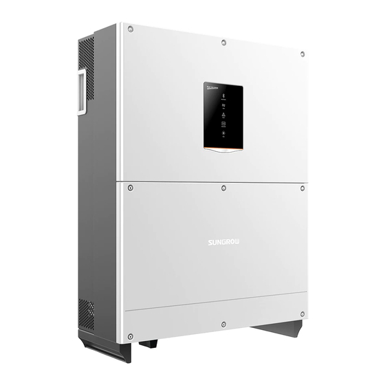
2 Product Description User Manual TN-S TN-C TN-C-S Transformer Transformer Transformer SG125HV SG125HV SG125HV Transformer Transformer SG125HV SG125HV 2.2 Product Introduction 2.2.1 Appearance Fig. 2-2 Appearance * Pictures are indicative only. Product in kind prevail. -
Page 16: Dimensions
User Manual 2 Product Description Name Description HMI interface to indicate the present working LED indicator panel state of the inverter. Protective components to safely disconnect DC DC switch side current. Waterproof air valve Electrical connection Includes DC terminal, AC terminal and RS485 area communication terminal. - Page 17 2 Product Description User Manual Fig. 2-4 LED indicator panel Tab. 2-1 State description of the LED indicator panel LED indicator LED color LED state Definition No device connected to the inverter through the Bluetooth. Bluetooth Blue The Bluetooth communication Periodical is connected and there is data flash...
-
Page 18: Dc Switch
User Manual 2 Product Description LED indicator LED color LED state Definition Both the AC and DC is powered down, or a fault occurs The DC or AC is powered on Normal Green Periodical and the device is in standby or operation flash startup state (not connect to... -
Page 19: Function Description
Filter DC SPD AC SPD Auxiliary Power DSP+FPGA LED/RS485 Fans Fig. 2-5 Circuit diagram of SG125HV 2.3.2 Function Description Inversion function The inverter converts the DC current into grid-compatible AC current and feeds the AC current into grid. ... -
Page 20: Derating
User Manual 2 Product Description -Ambient temperature monitoring -DC over-voltage protection -Over-current protection -Power module over-temperature protection 2.3.3 Derating Output derating is a way to protect the inverter form overload or potential faults. Situations requiring inverter power derating are: Ambient temperature is too high ... - Page 21 2 Product Description User Manual Output Power Vmpp=860V Vmpp=1050V Vmpp=1250V Temperature(℃) Lower limit of the over-temperature derating: about 50% of the nominal power. When both the module temperature and the internal temperature meet the derating condition, inverter limits its power according to the lower power limitation value of the two.
- Page 22 User Manual 2 Product Description High input voltage derating If the input voltage is too high, the inverter may derate the power output. The relationship between the input voltage and the power derating is shown in the figure below. Output Power 62.5 Vmpp V 1250...
-
Page 23: Installation Flow
3 Installation Flow Fig. 3-1 shows the installation flow of the inverter and Tab. 3-1 gives a detailed explanation. Start Select mounting location Move inverter Unpacking and Inspection Read User Manual Install inverter Electrical connection Check before commissioning Commissioning Troubleshooting Success? Fig. - Page 24 User Manual 3 Installation Flow Tab. 3-1 Description of installation flow Step Description Reference Select optimal installation site Move the inverter to the installation site Unpacking and inspection Read the User Manual, especially the section on “Safety Instruction” Install the inverter to the selected installation site Electrical connection;...
-
Page 25: Unpacking And Storage
Check the completeness of delivery contents according to the packing list. Check the inner contents for damage after unpacking. If any damage is found, please contact Sungrow or the forwarding company. Do not dispose of the original packaging. It is best to store the inverter in its original packaging. - Page 26 Ambient Temperature -13°F to+140°F (>122°F derating) Non-isolated Inverter Ground-fault Detector and Interrupter Grid Support Interactive Inverter 253758 SUNGROW POWER SUPPLY CO., LTD. WWW.SUNGROWPOWER.COM MADE IN CHINA Fig. 4-2 Inverter nameplate *Image shown here is indicative only. Product in kind prevail. Item...
-
Page 27: Scope Of Delivery
4.4 Inverter Storage Proper storage is required if the inverter is not installed immediately. Sungrow shall hold no liability for the damage of the device, in appearance or the failure of internal components, caused by improper storage of the device as specified in this manual. - Page 28 The packing should be upright. If the inverter is stored for half a year or longer, the local installer or service dept. of Sungrow should perform a comprehensive test before connecting the inverter into a PV power system.
-
Page 29: Mechanical Installation
5 Mechanical Installation 5.1 Installation Site Selection Select an optimal installation site for safe operation, long service life and outstanding performance. Take the load capacity of the wall into account. The wall (concrete wall or metal frame) should be strong enough for the weight of the inverter over a long period. - Page 30 It is recommended to install the inverter on the frame if you select the titled installation or the horizontal installation method. Sungrow will provide a detailed frame installation solution. If you do not use the frame to install the inverter, please make sure the installation location meets the requirement described in this section.
- Page 31 5 Mechanical Installation User Manual The frame is an optional accessary. Please order it from Sungrow. You can also use a self-made frame after consulting Sungrow. With an NEMA 4X protection rating, the Max. ambient inverter can be installed both outdoors and temperature: +140°F...
-
Page 32: Moving Inverter To Installation Site
User Manual 5 Mechanical Installation 5.2 Moving Inverter to Installation Site To install the inverter, remove the inverter from the packaging and move it to the installation site. Follow the instructions below as you move the inverter: Always be aware of the weight of the inverter. ... -
Page 33: Installing To Metal Frame
5 Mechanical Installation User Manual 20.4 2-M4×10 18.1 Fig. 5-1 Dimensions of the bracket (figures in inch) The stainless fasteners are supplied for attaching the bracket to metal frame. Fig. 5-2 Dimensions of fastener for metal frame (figures in mm) To install the inverter to concrete walls, the user needs to purchase expansion bolts with proper size (recommended: M10*65) to attach the bracket to concrete walls. -
Page 34: Installing To Concrete Wall
User Manual 5 Mechanical Installation Secure the bracket to the metal frame firmly with the supplied fastener. Step 5 The torque of the fasten nut is 35 Nm. Install backplate Name Description Hexagon nut Spring washer Flat washer Screw bolt M10*45 Metal frame Bracket... - Page 35 5 Mechanical Installation User Manual bracket. Drill holes according to the marks made before. Step 4 Check to ensure that there is no other electronic or plumbing installed inside the wall before drilling holes. Mark positions Drill holes Secure the bracket to the wall firmly by the supplied expansion bolt sets. Step 5 Torque of the fasten nut is 35 Nm.
- Page 36 User Manual 5 Mechanical Installation M12-screwed lifting ring is a standard component. It is not within the scope of delivery. Please purchase from the market if needed. Thread a rope (with sufficient load-carrying capacity) prepared Step 8 beforehand through the two lifting rings to lift the inverter and lift the inverter to the level of the attached bracket or adjacent location.
-
Page 37: Electrical Connection
6 Electrical Connection Once the inverter is secured to the installation site, it can be connected to the PV system. All electrical connections must comply with local regulations and related electrical rules. Improper cable connection may lead to a fatal injury or permanent damage to the device. - Page 38 User Manual 6 Electrical Connection Bottom view Fig. 6-1 Cable connection area *Pictures are indicative only. Please in kind prevail. Name Description Protective components safely DC switch disconnect DC side current. Communication cable connection Configuration circuit board configuration DC crimping terminal DC input cable access AC crimping terminal AC output cable access...
-
Page 39: Dimensions Of Terminal
6 Electrical Connection User Manual If you need the Tracker function, please order the Tracker control cabinet from Sungrow. Please refer to the user manual of the Tracker control cabinet for detailed installation and cable connection instructions of the device. -
Page 40: Ac Side Cable Connection
Several inverters are in parallel connection to the low voltage side of the MV transformer. The high voltage side is connected to the medium voltage grid. Requirements: If the number of the grid-connected inverters exceed 40, please contact Sungrow. - Page 41 When the utility side phase monitoring devices are absence, and the system fully relies on inverter protection to shut down during the loss of phase fault at the utility side, Sungrow recommends a transformer with a DELTA connection on the utility side.
-
Page 42: Grid Connection
User Manual 6 Electrical Connection The transformer shall be capable of withstanding a certain level of DC current injection. 0.5% of the fundamental current at nominal power. The transformer shall be capable of withstanding a certain degree of phase imbalance. - Page 43 6 Electrical Connection User Manual The maximum operation temperature of the cable should no less than 90° The current rating of the cable should be selected in accordance with the maximum AC output current of the inverter. The voltage rating of the cable should no less than 600Vac.
- Page 44 User Manual 6 Electrical Connection Description Remark Conduit Length of insulation to be stripped off Insulation layer Cross section Range: ≤350Kcmil cables Insert the end of the AC cable into the compression lug that matches with Step 4 the M8 bolt and tighten it with proper tool. Install the heat-shrinkable tubing.
-
Page 45: Connecting Inverter To Pv Arrays
6 Electrical Connection User Manual because the inverter can self-adapt. Observe the pin assignment of AC terminal block. If a phase wire is connected to the “PE” terminal, it may permanently damage the inverter. Please avoid squeezing the cable insulation layer into the AC terminal. -
Page 46: Pv Input Connection
String #N ● ● ● The SG125HV is a single stage inverter with only one MPPT. To make full use of the DC input power and reduce the power loss caused by mismatch, the type and rating of the PV modules connected to one inverter should be the same, including: ◇the same PV module model;... - Page 47 6 Electrical Connection User Manual compression lugs or terminals to avoid the direct connection between copper and aluminum conductors. The DC cable must be selected in accordance with the local installation requirements. The cross sectional area of DC cables cannot be more than 350 Kcmil. DC Cable Connection High voltage inside the inverter! Make sure all DC and AC cables connected to the inverter are...
-
Page 48: Grounding The Inverter
Once positive and negative inputs are short-circuited, it can cause unrecoverable damage to the inverter. Sungrow shall hold no liability for any possible consequences caused by ignorance of this warning. Check the positive and negative polarity of the PV cells. After confirmation, you can insert the DC connectors into the input terminals on the bottom of the inverter. -
Page 49: Grounding System Overview
6 Electrical Connection User Manual 6.4.1 Grounding System Overview In this PV system, all non-current carrying metal parts and device enclosure should be grounded (such as the PV array frame and inverter enclosure). When there is only one inverter in the PV system, ground the PE cable. When there are multiple inverters in the PV system, they can be multi-point grounded. -
Page 50: Communication Overview
The ground connection of this second PE terminal cannot replace the connection of the PE terminal of the AC cables. Make sure the two PE terminals are all grounded reliably. Sungrow shall hold no liability for any possible consequences caused by ignorance of this warning. -
Page 51: Rs485 Communication Connection
6 Electrical Connection User Manual be connected between the A and B communication cable through the dip switch. 120Ω terminating resistor switch Configuration circuitboard RS485_2 ALARM RS485_1 COM1 COM1 NC1 NO1 PGND DIN1 PGND DIN1 LOCAL STOP Fig. 6-5 Communication configuration The inverter operation information can be transferred to the PC of the installed monitoring software (e.g. -
Page 52: Rs485 Communication System
User Manual 6 Electrical Connection Inverter RS485-2 Data Logger RS232 RS485 Communication of single inverter Communication Terminating Inverter connection (RS485 Resistor connection) Only out 120ohm Single inverter For Multiple Inverters Where there is more than one inverter, all inverters can be connected in a daisy chain through an RS485 communication cable. - Page 53 6 Electrical Connection User Manual Inverter 1 Inverter 2 Inverter n RS485-2 RS485-2 RS485-2 120Ω Data Logger RS232 RS485 Shielding layer is grounded Multiple inverters in daisy chain Communication Terminating Resistor Inverter connection (RS485 n>15 n≤15 connection) Only out 120ohm 120ohm Inverter 1 In and Out...
-
Page 54: Rs485 Communication Architecture Diagram
User Manual 6 Electrical Connection ● ● ● ● ● ● ● ● ● Fig. 6-6 RS485 communication architecture diagram... - Page 55 6 Electrical Connection User Manual 6.5.4 RS485 Communication Connection RS485A/B Bus Connection Thread the Network cable through communication cable gland to the Step 1 configuration circuit board. Strip off the insulation layer of the communication cable. Connect the A Step 2 and B of RS485 communication cable to corresponding terminals according to the marks on the configuration circuit board.
-
Page 56: Rs485 Communication Connection
User Manual 6 Electrical Connection SolarInfo logger and RS485-232 converter are optional parts and can be ordered from Sungrow. RS485 RS232 6.6 Configurable Dry Contact There are Fault Alarm dry contacts and Local Stop dry contacts located on the configurable circuit board. - Page 57 6 Electrical Connection User Manual Local Stop dry contacts The dry contacts can be configured as Local Stop. When the two terminals PGND &DIN1 are short-circuited, the inverter will stop running immediately. The dry contacts only support passive switch signal input. •...
- Page 58 User Manual 6 Electrical Connection...
-
Page 59: Commissioning
7 Commissioning Commissioning is a critical procedure for a PV system, which can protect the system from fires, and personnel from injury and electrical shock. 7.1 Inspection before Commissioning Before starting the inverter, you should check the following items. Ambient Environment The inverter should be accessible for operation, maintenance and service. - Page 60 User Manual 7 Commissioning If the conditions are OK, the inverter feeds AC power to the grid and enters into the running state. Observe the status of LED indicator panel. Step 4 LED indicator LED color Definition state No device is connected to the inverter through the Bluetooth.
- Page 61 7 Commissioning User Manual LED indicator LED color Definition state the grid) The device is connected to the grid and operating normally Use the Sun Access App to establish the communication connection with Step 5 the inverter through Bluetooth to set the initial parameters. When the device is initialized, the App will send start instructions and the device will start and operate.
-
Page 62: Disconnecting, Dismantling And Disposing The Inverter54
8 Disconnecting, Dismantling and Disposing the Inverter 8.1 Disconnecting the Inverter For maintenance work or any service work, the inverter must be switched off. During normal operation, the inverter should remain switched on. Proceed as follows to disconnect the inverter from DC and AC power sources Disconnect the external AC circuit breaker or disconnect to prevent it Step 1 from accidentally reconnecting to the utility grid. -
Page 63: Disposal Of The Inverter
8 Disconnecting, Dismantling and Disposing the Inverter User Manual 8.3 Disposal of the Inverter System owners and the O&M company are responsible for the disposal of the inverter. Some parts and devices in the inverter, such as the LED indicator panel, batteries, modules and other components, may cause environmental pollution. -
Page 64: Troubleshooting And Maintenance
If the grid voltage is within the permissible requirements. range, contact Sungrow. This is a short-term fault due to grid Grid transient voltage conditions. Wait a moment for inverter exceeds the permissible recovery. - Page 65 Sungrow. The DC component of AC Wait for inverter recovery. current exceeds inverter If the fault still occurs, contact Sungrow. limit. Check the PV strings for ground fault. Fault current leakage is If the fault occurs repeatedly, contact detected Sungrow.
- Page 66 If the fault occurs repeatedly, contact Sungrow. This is a short-term fault. Wait for inverter Bus voltage fluctuation recovery If the fault still occurs, contact Sungrow. reverse connection Check the PV connection. fault Wait for inverter to return normal;...
- Page 67 Grid voltage redundancy permissible range, ask the local utility detection fault grid company for solution. grid voltage within permissible range, contact Sungrow Service Dept. Check the grid frequency; If the grid frequency exceeds the Grid frequency permissible range, ask the local utility...
-
Page 68: Maintenance
Check whether there is SPD waring Every Six months using APP. Replace the AC SPD and DC SPD (contact Sungrow) whenever necessary. 9.2.2 Maintenance Instruction Fan Maintenance Fans inside the inverter are used to cool the inverter during operation. If the fans do not operate normally, the inverter may not be cooled down and inverter efficiency may decrease. - Page 69 9 Troubleshooting and Maintenance User Manual maintenance. Lethal voltage still exists in the inverter even after the inverter has been switched off and disconnected. Please wait for at least ten minutes and then perform maintenance work. Only qualified electricians can maintain the fans. Disconnect the AC Switch.
-
Page 70: Contact Sungrow Service
Clean the air inlet and outlet with soft brush or vacuum cleaner if necessary. 9.3 Contact Sungrow Service Should you have any problems in operating on the inverter, please contact us: Service hotline: +86 551 65327817 Email: service@sungrow.cn... -
Page 71: Sun Access App
10 Sun Access APP 10.1 Introduction to the System By establishing a communication connection with the inverter through Bluetooth, the Sun Access APP can access near-end maintenance to the inverter. You can check the running info, alarms and events, set the parameters, download the logs and update the firmware through the APP. -
Page 72: Logging Sun Access App
10 Sun Access APP User Manual Click “Open” after the app is installed to open the app as shown in Fig. Step 2 10-1. You can also open the app by clicking the icon of the app in your phone desktop. Fig. - Page 73 10 Sun Access APP User Manual Fig. 10-2 Login Fig. 10-3 Nearby bluetooth list If you have no password, please click “login without password” to login and check certain info. Select the Bluetooth device to be connected and connect to that Step 3 Bluetooth as shown in Fig.
- Page 74 10 Sun Access APP User Manual Fig. 10-4 Device connection If the inverter is not initialized, you will enter the initialization protection Step 4 parameter quick setting interface as shown in Fig. 10-5 after the Bluetooth is connected. After setting the quick setting interface, click “Save”...
-
Page 75: Homepage
10 Sun Access APP User Manual The system interface may be different for different types of users. If you login by “login without password”, the app will not show the initialization protection parameter setting interface. The regular user can only set the country, instructions (valid for certain countries) and protection stage. -
Page 76: Run Info
10 Sun Access APP User Manual Fig. 10-7 Check the homepage info If a real-time alarm occurs in the inverter, there will be an alarm or fault icon appearing in the lower right corner of the inverter (circled by a box in the top of the interface). You can click this icon to get the detailed alarm or fault info. - Page 77 10 Sun Access APP User Manual Fig. 10-8 Run info Tab. 10-1 Description of Running Parameters Parameter Description the total PV input power Total DC power KW Input DC voltage(V) the input voltage DC current(A) the input current AC frequency Hz Total active power kW Output Apparent power(kVA)
-
Page 78: History Record
10 Sun Access APP User Manual Parameter Description In parallel resistance to ground kΩ Other Countries info Inverter selected country code Inverter selected command Command info information 10.6 History Record Click the “History” icon from the navigation bar to view the history record interface as shown in Fig. - Page 79 10 Sun Access APP User Manual Fig. 10-10 Fault alrm records If you need to check the alarm records within a certain period of time, please click the time selection bar on the top of the interface to select a certain period of time. The inverter can at most, record the latest 100 fault alarm instances.
-
Page 80: Power Yields Records
10 Sun Access APP User Manual 10.6.2 Power Yields Records User can view various energy records: power curve, daily energy histogram, daily energy histogram, monthly energy histogram, and annual energy histogram. Tab. 10-2 Explanation of power yields records Parameter Description Show the power output from 5am to 11pm in a single day. -
Page 81: Event Records
10 Sun Access APP User Manual Fig. 10-13 Power curve Swipe left to check the power yields histogram as shown in Fig. 10-14. Step 3 Fig. 10-14 power yields histogram 10.6.3 Event Records Click the “Event records” to check the event record list as shown in Fig. 10-15. -
Page 82: More
10 Sun Access APP User Manual Fig. 10-15 Event records If you need to check the event records within a certain period of time, please click the time selection bar on the top of the interface to select a certain period of time. The inverter can at most record the latest 100 events. -
Page 83: Power On/Power Off
10 Sun Access APP User Manual Fig. 10-16 More 10.7.1 Power On/Power Off Click “Power on”/”Power off” and click “Confirm” in the dialog box popped out to start or stop the inverter as shown in Fig. 10-17. Fig. 10-17 Power on... -
Page 84: System Parameters
10 Sun Access APP User Manual 10.7.2 System Parameters Click the “System parameters” to check the system parameter info and set the related parameters as shown in Fig. 10-18. Fig. 10-18 System parameter Tab. 10-3 Explanation of system parameters Parameter Description Date Setting Time deviation between the time on the inverter and the... - Page 85 10 Sun Access APP User Manual The operation parameters include the active & reactive power parameters. Fig. 10-19 Operation parameters Active & reactive power parameters Fig. 10-20 Active & reactive power parameters Tab. 10-4 Description of Active & reactive power parameters Parameter Description Default...
-
Page 86: Protection Parameters
User can only check the parameter in this interface. The default values of the protection parameters have been preset as per grid code of corresponding countries. To set the protection parameter, please contact Sungrow to acquire advanced password. Fig. 10-21 Protection parameter For convenient protection parameter setting, the protection parameters are preset for certain countries. -
Page 87: Communication Parameters
10 Sun Access APP User Manual Tab. 10-6 Multi-stage Protection Parameters Explanation Parameter Range Default AC under-voltage level 1 protection value 60V-600V 528V AC over-voltage level 1 protection value 477V-738V 660V AC under-frequency level 1 protection value 57Hz -59.9Hz 58.5Hz AC over-frequency level 1 protection value 60.1Hz -62Hz 60.5Hz... -
Page 88: Download The Log
10 Sun Access APP User Manual Fig. 10-22 Communication parameters Tab. 10-8 Explanation of communication parameters Parameter Description Device address Range: 1-247 10.7.6 Download the Log Click the “Download the log” to check the log download interface and download the logs as shown in Fig. 10-23 Fig. -
Page 89: About Sun Access
10 Sun Access APP User Manual 10.7.7 About Sun Access Click the “About Sun Access” to check the about interface as shown in Fig. 10-24. Fig. 10-24 About Sun Access... -
Page 90: Appendix
11 Appendix 11.1 Technical Data Parameters SG125HV Input Side Data Max. PV input voltage 1500V MPP voltage range 860 - 1450V MPP voltage range for 860 - 1250V nominal power No. of MPPT(s) Max.Short-circuit input 240A current of PV Output Side Data... -
Page 91: Exclusion Of Liability
11 Appendix User Manual Parameters SG125HV DC surge protection (type II), AC surge protection (type Overvoltage protection System data Max. efficiency 98.9% CEC efficiency 98.5% Isolation method Transformerless Degree of Protection NEMA 4X Night power <4W consumption Operating ambient -13°F to 140°F (>122°F derating) -
Page 92: About Us
The power rating of SUNGROW products covers a range from several hundred watts to large mega-watt systems. The pursuit of SUNGROW is to help our customers acquire stable and clean power with minimum cost, maximum reliability and enhanced safety. - Page 93 895 Edgeley Blvd, Vaughan, ON L4K 4V9 Add: Toll-Free +1 855 760 8618 Inquiry: Tel: +1 905 760 8618 Fax: +1 905 760 1158 Business: info@sungrow.ca, After-Sales service@sungrow.ca Website: www.sungrow.ca U.S.A 47751 Fremont Blvd., Fremont, CA 94538 Add: +1 510 324 6125 Tel:...
Need help?
Do you have a question about the SG125HV and is the answer not in the manual?
Questions and answers