
Related Manuals for Sungrow SG75CX-P2


Summary of Contents for Sungrow SG75CX-P2
- Page 1 User Manual PV Grid-Connected Inverter SG125CX-P2 / SG110CX-P2 / SG75CX-P2 SG125CX-P2 / SG110CX-P2 / SG75CX-P2PV Grid- Connected InverterUser ManualSG125_110_75CX-P2-UEN- Ver14-202212 SG125_110_75CX-P2-UEN-Ver14-202212...
-
Page 3: All Rights Reserved
Software Licenses • It is prohibited to use data contained in firmware or software developed by SUNGROW, in part or in full, for commercial purposes by any means. • It is prohibited to perform reverse engineering, cracking, or any other operations that... -
Page 4: About This Manual
Please read this manual carefully before using the product and keep it properly at a place for easy access. All contents, pictures, marks, and symbols in this manual are owned by SUNGROW. No part of this document may be reprinted by the non-internal staff of SUNGROW without written authorization. - Page 5 Symbols This manual contains important safety instructions, which are highlighted with the following symbols, to ensure personal and property safety during usage, or to help optimize the prod- uct performance in an efficient way. Please carefully understand the meaning of these warning symbols to better use the manual. Indicates high-risk potential hazards that, if not avoided, may lead to death or seri- ous injury.
-
Page 7: Table Of Contents
Contents All Rights Reserved .....................I About This Manual......................II 1 Safety Instructions ....................1 1.1 Unpacking and Inspection ................2 1.2 Installation Safety ...................2 1.3 Electrical Connection Safety................3 1.4 Operation Safety ....................4 1.5 Maintenance Safety ..................5 1.6 Disposal Safety ....................6 2 Product Description ..................7 2.1 System Introduction ..................7 2.2 Product Introduction..................8... - Page 8 4.5.3 Pole-Mounting ..................27 4.6 Installing Inverter ..................29 5 Electrical Connection ..................31 5.1 Safety Instructions ..................31 5.2 Terminal Description ..................33 5.3 Electrical Connection Overview ..............34 5.4 Crimp OT/DT terminal ...................37 5.5 External Protective Grounding Connection .............38 5.5.1 External Protective Grounding Requirements ........38 5.5.2 Connection Procedure.................39 5.6 AC Cable Connection ...................39 5.6.1 AC Side Requirements ................39...
- Page 9 6 Commissioning ....................74 6.1 Inspection Before Commissioning..............74 6.2 Commissioning Procedure ................74 7 iSolarCloud App ....................76 7.1 Brief Introduction ..................76 7.2 Installing App ....................76 7.3 Login ......................77 7.3.1 Requirements ..................77 7.3.2 Login Procedure .................77 7.4 Function Overview..................81 7.5 Home ......................81 7.6 Run Information....................84 7.7 Records .......................84 7.8 More......................87 7.8.1 System Parameters................87...
- Page 10 10.4 Contact Information .................. 120 VIII...
-
Page 11: Safety Instructions
Perform operations considering ac- tual onsite conditions. • SUNGROW shall not be held liable for any damage caused by violation of gen- eral safety operation requirements, general safety standards, or any safety in- struction in this manual. -
Page 12: Unpacking And Inspection
If there are problems with the above inspection items, do not install the device and contact your distributor first. If the problem persists, con- tact SUNGROW in time. Installation Safety •... -
Page 13: Electrical Connection Safety
User Manual 1 Safety Instructions Electrical Connection Safety • Before electrical connections, please make sure that the inverter is not dam- aged, otherwise it may cause danger! • Before electrical connections, please make sure that the inverter switch and all switches connected to the inverter are set to "OFF", otherwise electric shock may occur! The PV string will generate lethal high voltage when exposed to sunlight. -
Page 14: Operation Safety
1 Safety Instructions User Manual • Check the positive and negative polarity of the PV strings, and connect the PV connectors to corresponding terminals only after ensuring polarity correctness. • During the installation and operation of the inverter, please ensure that the posi- tive or negative poles of PV strings do not short-circuit to the ground. -
Page 15: Maintenance Safety
To avoid the risk of electric shock, do not perform any other maintenance opera- tions beyond those described in this manual. If necessary, contact your distributor first. If the problem persists, contact SUNGROW. Otherwise, the losses caused is not covered by the warranty. -
Page 16: Disposal Safety
1 Safety Instructions User Manual • If the paint on the inverter enclosure falls or rusts, repair it in time. Otherwise, the inverter performance may be affected. • Do not use cleaning agents to clean the inverter. Otherwise, the inverter may be damaged, and the loss caused is not covered by the warranty. -
Page 17: Product Description
The inverter applies only to the scenarios described in this manual. Description Item Note Monocrystalline silicon, polycrystalline silicon and thin-film PV strings without grounding. SG125CX-P2, SG110CX-P2, SG75CX-P2 Inverter Grid connection Includes devices such as AC circuit breaker, SPD, metering cabinet device. -
Page 18: Product Introduction
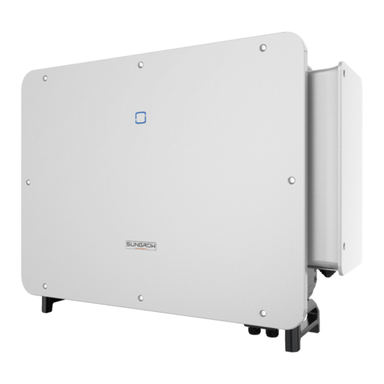
2 Product Description User Manual Description Item Note Boost the low voltage from the inverter to grid-compatible me- Transformer dium voltage.(Optional) The grid forms supported by the inverter are shown in the fig- Utility grid ure below. In a TT power grid, the N-PE voltage should be lower than 30 V. Product Introduction Model Description The model description is as follows (Take SG125CX-P2 as an example):... - Page 19 User Manual 2 Product Description Appearance figure 2-2 Inverter Appearance * The image shown here is for reference only. The actual product received may differ. Description Name LED indicator HMI interface to indicate the present working state of the panel inverter.
-
Page 20: Symbols On Product
2 Product Description User Manual figure 2-3 Product Dimensions(in mm) Weight Model Weight SG125/110CX-P2 87 kg SG75CX-P2 82 kg Symbols on Product Symbol Explanation Do not dispose of the inverter together with household waste. TÜV mark of conformity. CE mark of conformity. -
Page 21: Led Indicator
User Manual 2 Product Description Symbol Explanation Danger to life due to high voltages! Do not touch live parts for 5 minutes after disconnection from the power sources. Only qualified personnel can open and maintain the inverter. External protective grounding terminal. Read the user manual before maintenance! * The table shown here is for reference only. -
Page 22: Circuit Diagram
2 Product Description User Manual Voltage may still be present in AC side circuits after the indicator is off. Pay atten- tion to the electricity safety when operating. Circuit Diagram The following figure shows the main circuit of the inverter. figure 2-4 Circuit Diagram •... - Page 23 • The communication accessory port is used to connect communication module manufac- tured by SUNGROW, and upload monitoring data by means of wireless communication. The inverter can be connected to communication devices via either of the two interfaces. When communication is established between the inverter and the communication devices, users can view inverter information or set inverter parameters, such as running parameter and protection parameter, through the iSolarCloud.
- Page 24 2 Product Description User Manual • For negative voltage scheme, after the PID is enabled, the voltage to ground of all PV strings is lower than 0, and therefore the PV string-to-ground voltage is a negative value. • Before enabling the PID recovery function, make sure the voltage polarity of the PV modules to ground meets requirement.
-
Page 25: Unpacking And Storage
• Check the inner contents for damage after unpacking. Contact SUNGROW or the transport company in case of any damage or incompleteness, and provide photos to facilitate services. Do not dispose of the original packing case. It is recommended to store the device in the original packing case when the product is decommissioned. - Page 26 3 Unpacking and Storage User Manual • Do not store the inverter in places susceptible to direct sunlight, rain, and strong electric field. • Do not place the inverter in places with items that may affect or damage the inverter. •...
-
Page 27: Mechanical Mounting
Mechanical Mounting Respect all local standards and requirements during mechanical installation. Safety During Mounting Make sure there is no electrical connection before installation. Before drilling, avoid the water and electricity wiring in the wall. Poor installation environment will affect system performance! •... -
Page 28: Location Requirements
4 Mechanical Mounting User Manual Location Requirements To a large extent, a proper installation location ensures safe operation, service life, and per- formance of the inverter. • The inverter with protection rating IP66 can be installed both indoors and outdoors. •... -
Page 29: Angle Requirements
User Manual 4 Mechanical Mounting the weight of the inverter and is suitable for the dimensions of the inverter (e.g. cement walls, plasterboard walls, etc.). 4.2.3 Angle Requirements Install the inverter vertically or at the maximum allowable rear tilt angle. Do not install the in- verter horizontally, forward, excessively backward, sideways, or upside down. -
Page 30: Clearance Requirements
4 Mechanical Mounting User Manual Take the following items into account when designing the bracket scheme: • Consider onsite climate conditions and take anti-snow and anti-rain measures if necessary. • Ensure that the waterproof connectors are at least 300mm higher than the ground surface. -
Page 31: Installation Tools
User Manual 4 Mechanical Mounting Back to Back Installation When installing inverters back-to-back, the distance between every two inverters should be at least 600 mm. Add a baffle between the two inverters to form a heat dissipation channel. The baffle plate should be placed horizontally between two inverters and should not block the air outlet of inverters. - Page 32 4 Mechanical Mounting User Manual Safety shoes Utility knife Slotted screwdriver Phillips screwdriver (M2, M3, M6) (M4, M6, M8) Hammer drill Pliers Marker Level (φ12) Rubber mallet Socket wrench set Anti-static wrist strap Open-end wrench (M4, M8, M12) (16 mm, 33 mm) Wire cutter Wire stripper Hydraulic plier...
-
Page 33: Moving Inverter
User Manual 4 Mechanical Mounting Moving Inverter Before installation, remove the inverter from the packing case and move it to the installation site. It is recommended to use the four screw-in handles and the Bottom handles to move the in- verter. -
Page 34: Pv Bracket-Mounted Installation
4 Mechanical Mounting User Manual figure 4-1 Dimensions of Mounting-bracket 4.5.1 PV Bracket-Mounted Installation Tools Item Specification Phillips screwdriver / electric screw driver Marker Level Electric drill Drill bit: φ12 Wrench Opening: 16 mm Spare parts Item Quantity Specification Source Grub screw M4×10 Delivery scope... -
Page 35: Wall-Mounted Installation
User Manual 4 Mechanical Mounting step 3 Secure the mounting-bracket with bolts. (A) Mounting-bracket (B) Full threaded bolt (C) Metal bracket (D) Flat washer (E) Spring washer (F) Hex nuts - - End 4.5.2 Wall-Mounted Installation Tools Item Specification Phillips screwdriver / electric screw driver Marker Level... - Page 36 4 Mechanical Mounting User Manual Item Quantity Specification Source Grub screw M4×10 Delivery scope Bolt assembly M10×95 Self-prepared (Recommended) step 1 Assemble the mounting-bracket. step 2 Level the assembled mounting-bracket by using the level, and mark the positions for drilling holes.
-
Page 37: Pole-Mounting
User Manual 4 Mechanical Mounting (A) Wall (B) Expansion bolt (C) Mounting-bracket - - End 4.5.3 Pole-Mounting Tools Item Specification Phillips screwdriver / electric screw driver — Marker — Level Electric drill * Drill bit: φ12 wrench Opening: 16 mm * Check whether other tools are needed according to the specification of clamp bolts. - Page 38 4 Mechanical Mounting User Manual step 3 Mark and punch holes in the U-beam according to the dimensions shown below. step 4 Use bolts and clamps to fix the U-beam to the pole.
-
Page 39: Installing Inverter
User Manual 4 Mechanical Mounting step 5 Use bolts to secure the mounting-bracket to the U-beam. - - End Installing Inverter Tools Item Specification Phillips screwdriver / electric screw driver Spare parts Quantity Specification Item Source Delivery scope Grub screw M6×65 step 1 Take out the inverter from the packing case. - Page 40 4 Mechanical Mounting User Manual step 3 Fix the inverter with screws. It is necessary to fix the left and right sides of the inverter with screws. Otherwise, the inverter may be unstable. - - End...
-
Page 41: Electrical Connection
Electrical Connection Safety Instructions The PV string will generate lethal high voltage when exposed to sunlight. • Operators must wear proper personal protective equipment during electrical connections. • Must ensure that cables are voltage-free with a measuring instrument before touching DC cables. •... - Page 42 5 Electrical Connection User Manual All electrical connections must comply with local and national/regional electrical standards. • Cables used by the user shall comply with the requirements of local laws and regulations. • Only with the permission of the national/regional grid department, the inverter can be connected to the grid.
-
Page 43: Terminal Description
Terminal Description All electrical terminals are located at the side and bottom of the inverter. figure 5-1 Terminal Description(SG125/110CX-P2) figure 5-2 Terminal Description(SG75CX-P2) * The image shown here is for reference only. The actual product received may differ. Item Terminal... -
Page 44: Electrical Connection Overview
5 Electrical Connection User Manual Item Terminal Mark Note Standby Used for internal grounding. — grounding terminal* Used for internal grounding. — PE terminal RS485 communication, digital input/output DI/ Communica- COM1,COM2 DO, etc. tion terminal External pro- tective use at least one of them to ground the inverter. grounding terminal *If the PE cable is an independent single-core cable, it should be inserted into the AC junc-... - Page 45 User Manual 5 Electrical Connection Specification Type Cable Cable Diame- Cross-sectional Area ter(mm) Additional Outdoor single- The same as that of the PE wire in the AC grounding core copper wire cable cable cable Outdoor five-core 30 ~ 60 copper wire cable L1, L2, L3, N wire: 70 ~ L1, L2, L3, N Outdoor four-core...
- Page 46 Other sizes of grounding cables that meet local standards and safety regulations can also be used for grounding connections. But SUNGROW shall not be held liable for any damage caused.
-
Page 47: Crimp Ot/Dt Terminal
User Manual 5 Electrical Connection Crimp OT/DT terminal Crimp OT/DT terminal 1. Heat shrink tubing 2. OT/DT terminal 3. Hydraulic pliers 4. Heat gun Aluminum Cable Requirements If an Aluminum cable is selected, use a copper to Aluminum adapter terminal to avoid direct contact between the copper bar and the Aluminum cable. -
Page 48: External Protective Grounding Connection
AC side grounding terminal are reliably grounded. The grounding connection can be made by other means if they are in accordance with the local standards and regulations, and SUNGROW shall not be held liable for the possible consequences. -
Page 49: Connection Procedure
User Manual 5 Electrical Connection When there are multiple inverters in the PV system, connect the external protective ground- ing terminals of all inverters and the grounding points of the PV module brackets to ensure equipotential connections to ground cables (according to the onsite conditions). 5.5.2 Connection Procedure step 1 Prepare the cable and OT/DT terminal, refer to "... - Page 50 SG125CX-P2 400V 250A SG110CX-P2 400V 250A SG75CX-P2 400V 160A AC circuit breakers should be installed on the output side of the inverter and the grid side to ensure safe disconnection from the grid. • Determine whether an AC circuit breaker with greater overcurrent capacity is re- quired based on actual conditions.
-
Page 51: Requirements For Ot/Dt Terminal
User Manual 5 Electrical Connection • The line-to-line voltage on the HV side of the transformer should comply with the local power grid voltage. • A transformer with a tap changer on the HV side is recommended in order to keep the voltage consistent with the grid voltage. -
Page 52: Connection Procedure (For A Multi-Core Cable)
5 Electrical Connection User Manual OT/DT Terminals of Phase Wire • Specification: M12 figure 5-5 Specifications of the Crimped OT/DT Terminal OT/DT Terminal of PE Wire • Specification: M12 5.6.3 Connection Procedure (For a multi-core cable) In this manual, description is given by using five-core cable as an example. The wiring of the four-core cable is the same. - Page 53 User Manual 5 Electrical Connection The screws on the sealing plate are captive screws. When the sealing plate is re- moved, the screws remain on it. step 4 Cut off the excess part of sealing ring according to cable diameter. step 5 Lead the cable with the protective layer stripped through the sealing ring and secure screws on the bottom sealing plate.
- Page 54 5 Electrical Connection User Manual step 6 Open the protective cover. step 7 Connect cables with crimped OT/DT terminals to corresponding terminals and secure them. Please fasten AC terminals referring to the torque specified on the label inside the AC box. Note the terminal positions of PE wire and N wire.
- Page 55 User Manual 5 Electrical Connection Ensure that the depth L of the socket used is not less than 28mm. step 8 Close the protective cover. step 9 Remove the limit rod and put it back. Close the junction box and tighten the two screws on the front cover using the supplied hexagon socket wrench.
-
Page 56: Connection Procedure (For A Single-Core Cable)
5 Electrical Connection User Manual - - End *If the PE cable is an independent single-core cable, it is inserted into the cabinet through the standby grounding terminal. 5.6.4 Connection Procedure (For a single-core cable) step 1 Disconnect the AC-side circuit breaker and prevent it from inadvertent reconnection. step 2 Loosen two screws on the front cover of the junction box using the supplied hexagon socket wrench, and open the junction box. - Page 57 User Manual 5 Electrical Connection The screws on the front cover are captive screws. When the front cover is opened, the screws remain on it. step 3 Loosen screws on the bottom sealing plate using the supplied hexagon socket wrench, and remove the sealing plate.
- Page 58 5 Electrical Connection User Manual step 5 Lead the cable through the sealing ring and secure the screws on the bottom sealing plate. step 6 Open the protective cover.
- Page 59 User Manual 5 Electrical Connection step 7 Connect cables with crimped OT/DT terminals to corresponding terminals and secure them. Please fasten AC terminals referring to the torque specified on the label inside the AC box. Note the terminal positions of PE wire and N wire. If a phase wire is connected to the PE terminal or N terminal, unrecoverable damage may be caused to the inverter.
-
Page 60: Dc Cable Connection
5 Electrical Connection User Manual step 9 Remove the limit rod and put it back. Close the junction box and tighten the two screws on the front cover using the supplied hexagon socket wrench. - - End DC Cable Connection The PV string will generate lethal high voltage when exposed to sunlight. - Page 61 User Manual 5 Electrical Connection • Make sure the PV array is well insulated to ground before connecting it to the inverter. • Make sure the maximum DC voltage and the maximum short circuit current of any string never exceed inverter permitted values specified in "Technical Data". •...
-
Page 62: Pv Input Configuration
5 Electrical Connection User Manual Note the following items when laying out cables on site: • The axial tension on PV connectors must not exceed 80 N. Avoid axial cable stress on the connector for a long time during field wiring. •... -
Page 63: Assembling Pv Connectors
• Do not connect the AC circuit breaker before finishing electrical connection. SUNGROW provides corresponding PV connectors in the scope of delivery for quick connection of PV inputs. To ensure IP66 protection, use only the supplied connector or the connector with the same ingress of protection. -
Page 64: Installing Pv Connector
5 Electrical Connection User Manual step 5 Check for polarity correctness. If the PV polarity is reversed, the inverter will be in a fault or alarm state and will not operate normally. - - End 5.7.3 Installing PV Connector step 1 Ensure that the DC switch is in "OFF" position. Otherwise, manually turn it to "OFF". step 2 Check the cable connection of the PV string for polarity correctness and ensure that the open circuit voltage in any case does not exceed the inverter input limit of 1,100 V. -
Page 65: Wiring Of Tracking System Power Cable (Optional)
User Manual 5 Electrical Connection The multimeter must have a DC voltage range of at least 1100 V. If the voltage is a negative value, the DC input polarity is incorrect. Please correct the DC input polar- ity. If the voltage is greater than 1100 V, too many PV modules are configured to the same string. - Page 66 5 Electrical Connection User Manual step 3 Lead the cable through the seal ring. The length of unstripped cable in the AC junction box is 50mm. step 4 Place the OT terminals of power cable for tracking system on the OT/DT terminals of the AC cable, and secure them.
-
Page 67: Wireless Communication Module Connection(Optional)
User Manual 5 Electrical Connection The power cables for tracking system can be connected to any two phases among L1, L2, and L3. step 5 Close the protective cover. Close the junction box and tighten the two screws on the front cover using the supplied hexagon socket wrench. -
Page 68: Winet-S Connection (Optional)
5 Electrical Connection User Manual Once the communication module is in use, do not connect the inverter to a 3rd party data logger at the same time via RS485. For details on module installation and configuration, refer to the manual delivered together with the module. - Page 69 User Manual 5 Electrical Connection step 3 Unscrew the housing from the communication module. step 4 Thread the network cable through the swivel nut and gasket. Afterwards, route the cable into the opening of the sealing. Finally, insert the cable through the housing. step 5 Insert the RJ45 plug into the front plug connector until there is an audible click and tighten the housing.
-
Page 70: Wlan Communication
5 Electrical Connection User Manual step 6 Remove the waterproof lid from the COM1 terminal and install WiNet-S. step 7 Slightly shake it by hand to determine whether it is installed firmly. - - End 5.10.2 WLAN Communication step 1 Remove the waterproof lid from the COM1 terminal. step 2 Install the module. -
Page 71: Communication Wiring Board
User Manual 5 Electrical Connection Install the Communication Junction Box Put the junction box back and ensure a firm connection. 5.12 Communication Wiring Board The inverter communication board consists of two layers, RS485 communication interface on the upper layer, and DI/DO interface on the lower layer. -
Page 72: Rs485 Connection
5 Electrical Connection User Manual table 5-3 Port description Description Silk Screen RS485_3 Used to connect the external meter Used to connect the external COM100E to realize data interaction with host computer or other moni- RS485_1 toring devices Used for multiple inverters in the daisy chain to communicate RSD STOP Reserved... -
Page 73: Rs485 Communication System
User Manual 5 Electrical Connection Description RS485B OUT,RS485B differential signal- RS485B IN,RS485B differential signal- table 5-5 RS485_1 interface (RJ45)description Description PIN 1 ~ 2 RS485B differential signal- PIN 3 PIN 4 ~ 5 RS485A differential signal+ PIN 6 PIN 7 ~ 8 table 5-6 RS485_3 terminal description Description RS485A differential signal+... -
Page 74: Connection Procedure(Terminal Block)
5 Electrical Connection User Manual figure 5-6 Multi-inverter Communication System 【RS485_1 interface (terminal block)】 figure 5-7 Multi-inverter Communication System 【RS485_1 interface (RJ45)】 The length of an RS485 cable cannot exceed 1200m. If multiple inverters communicate via the smart communication box, the number of permissible daisy chains and the number of devices allowed to be connected should meet the requirements (refer to the user manual of the smart communica- tion box). - Page 75 User Manual 5 Electrical Connection step 2 Unscrew the swivel nut of the junction box and select the sealing ring according to the cable diameter. step 3 Strip off the protective layer and insulation layer of proper length. step 4 Lead the cable through the swivel nut, the sealing ring and the junction box in sequence. Outer Diameter D(mm) Sealing Rings 4.5 ~ 6...
-
Page 76: Connection Procedure (Rj45 Interface)
5 Electrical Connection User Manual step 7 If other cables should be connected to the communication circuit board, skip the subsequent steps and continue wiring. Otherwise, perform as follows. step 8 Install the communication junction box, referring to" Install the Communication Junction Box"。... -
Page 77: Dry Contact Connection
User Manual 5 Electrical Connection Pins 1 and 2 supply power to the SUNGROW communication module. Do not con- nect or use these two pins when making an RS485 communication cable. Other- wise, the inverter or other devices connected through the communication cable may be damaged. - Page 78 5 Electrical Connection User Manual DO terminal (fault output dry contact) The relay can be set to output fault alarms, and user can configure it to be a normally open contact (COM&NO) or a normally closed contact (COM&NC). The relay is initially at the NC contact, and it will trip to another contact when a fault occurs. When alarm occurs, signal status change will not be triggered.
- Page 79 User Manual 5 Electrical Connection AC-Side Requirements DC-Side Requirements Max. voltage: 230 Vac Max. voltage: 24 Vdc Max. current: 3 A Max. current: 3 A DI terminal (emergency stop dry contact) The dry contact can be configured to be an emergency stop contact. When the DI contact and PGND contact are shorted by external controlled switch (The ex- ternal switch can be configured as normally open contact or normally closed contact), the in- verter will immediately shutdown.
-
Page 80: Wiring Procedure
5 Electrical Connection User Manual figure 5-10 Local stop contact figure 5-11 Daisy chain topology When wiring DI dry contacts, ensure that the maximum wiring distance meet the require- ments in "10.2 Wring Distance of DI Dry Contact". 5.14.2 Wiring Procedure Connection method of the dry contacts is similar to that of the RS485 terminal block. -
Page 81: Connection Procedure
20 kΩ Enable the DRM function through the iSolarCloud App. If there are any problems, contact your distributor first. If the problem persists, contact SUNGROW. The DRM function is only applicable to devices for Australia and New Zealand. 5.15.2 Connection Procedure step 1 Remove the communication junction box, referring to"... - Page 82 5 Electrical Connection User Manual Outer Diameter D(mm) Sealing Rings 4.5 ~ 6 6 ~ 12 a + b 12 ~ 18 step 3 Strip the insulation layer of the Ethernet cable with a wire stripper, and insert the signal wires to the RJ45 connector.
- Page 83 User Manual 5 Electrical Connection - - End...
-
Page 84: Commissioning
Commissioning Inspection Before Commissioning Check the following items before starting the inverter: • All equipment has been reliably installed. • DC switch(es) and AC circuit breaker are in the "OFF" position. • The ground cable is properly and reliably connected. •... - Page 85 User Manual 6 Commissioning step 2 Close the AC circuit breaker between the inverter and the grid. step 3 Install the iSolarCloud App, see "7.2 Installing App" for details. step 4 Set initial protection parameters via the iSolarCloud App when the inverter is connected to the grid for the first time (see Step 4 in "7.3.2 Login Procedure"...
-
Page 86: Isolarcloud App
iSolarCloud App Brief Introduction The iSolarCloud App can establish communication connection to the inverter via the Blue- tooth, thereby achieving near-end maintenance on the inverter. Users can use the App to view basic information, alarms, and events, set parameters, or download logs, etc. *In case the communication module Eye, WiFi or WiNet-S is available, the iSolarCloud App can also establish communication connection to the inverter via the mobile data or WiFi, thereby achieving remote maintenance on the inverter. -
Page 87: Login
User Manual 7 iSolarCloud App Login 7.3.1 Requirements The following requirements should be met: • The AC or DC side of the inverter is powered-on. • The mobile phone is within 5 meters away from the inverter and there are no obstructions in between. - Page 88 7 iSolarCloud App User Manual figure 7-1 Bluetooth Connection step 3 Enter the identity verification interface after the Bluetooth connection is established.
- Page 89 If the dis- tributor is unable to provide the required information, contact SUNGROW. step 4 If the inverter is not initialized, you will enter the quick setting interface of initializing protec- tion parameter.
- Page 90 7 iSolarCloud App User Manual figure 7-4 Initialization Power Company The image shown here is for reference only. Refer to the actual interface for the supported network service providers. table 7-1 Power Company Information Grid Type Network Service Provider AS/NZS 4777.2:2015 AS/NZS 4777.2:2020 Australia A AS/NZS 4777.2:2020 Australia B AS/NZS 4777.2:2020 Australia C...
-
Page 91: Function Overview
User Manual 7 iSolarCloud App Grid Type Network Service Provider SA Power Networks • TS129-2019: < 10 kW for single-phase & 30 kW for three-phase • TS130-2017: > 30 kW & ≤ 200 kW • TS131-2018: > 200 kW Horizon Power •... - Page 92 7 iSolarCloud App User Manual figure 7-6 Home Page table 7-2 Home Page Description Designation Description System date and time of the inverter. Date and time Present operation state of the inverter. For details, refer to Inverter state "table 7-3 Description of Inverter State".
- Page 93 User Manual 7 iSolarCloud App table 7-3 Description of Inverter State Description State After being energized, the inverter tracks the PV arrays’ maximum power point (MPP) and converts the DC power into AC power. This is the nor- mal operation mode. Stop The inverter is stopped.
-
Page 94: Run Information
7 iSolarCloud App User Manual Run Information Tap Run Information on the navigation bar to enter the screen showing running information, slide the screen upwards to view all detailed information. The run information includes the PV information, inverter information, input information, and output information. - Page 95 User Manual 7 iSolarCloud App figure 7-8 Fault Alarm Record to select a time segment and view corresponding records. The inverter can record up to 400 latest entries. Select one of the records in the list and tap the record to view the detailed fault information as shown in following figure.
- Page 96 7 iSolarCloud App User Manual figure 7-10 Power Curve The App displays power generation records in a variety of forms, including daily power gen- eration graph, monthly power generation histogram, annual power generation histogram and total power generation histogram. table 7-5 Yield Record Explanation Description Parameter Shows the power output from 5 am to 11 pm in a single day.
-
Page 97: More
User Manual 7 iSolarCloud App More Tap More on the navigation bar to enter the corresponding interface, as shown in the follow- ing figure. figure 7-11 More 7.8.1 System Parameters Tap Settings→System Parameters to enter the corresponding interface, as shown in the following figure. - Page 98 7 iSolarCloud App User Manual figure 7-13 Running Time PID Parameters Tap Settings→Operation Parameters→PID Parameters to enter the corresponding interface. figure 7-14 PID Parameters table 7-6 PID Parameter Description Description Parameter Enable/Disable the PID night recovery function. Once enabled, it PID Recovery works between 22:00 pm and 5:00 am by default.
-
Page 99: Power Regulation Parameters
User Manual 7 iSolarCloud App figure 7-15 AFCI Setting NS Protection (Passive Valid) Tap Settings→Operation Parameters→Regular Parameters to enter the corresponding screen, on which you can set the NS Protection(Passive Valid). figure 7-16 NS Protection(Passive Valid) 7.8.3 Power Regulation Parameters Active Power Regulation Tap Settings→Power Regulation Parameters→Active Power Regulation to enter the screen, as shown in the following figure. - Page 100 7 iSolarCloud App User Manual figure 7-17 Active Power Regulation table 7-7 Active Power Regulation Definition/Setting Range Parameter Description The switch for enabling/dis- Active power soft start abling the soft start function Enable/Disable after fault after a fault occurs. Time that the soft start takes to Active power soft start raise the power from 0 to 1s~1200s...
- Page 101 User Manual 7 iSolarCloud App Definition/Setting Range Parameter Description Switch for enabling/disabling Active power setting the function of saving output Enable/Disable persistence limited power. The switch for limiting output Active power limit Enable/Disable power. The ratio of limiting output Active power limit ratio power to rated power in 0%~110% percentage.
- Page 102 7 iSolarCloud App User Manual figure 7-18 Reactive Power Regulation table 7-8 Reactive Power Regulation Definition/Setting Range Parameter Description Reactive power gener- Switch for enabling/disabling Enable/Disable ation at night Q at night function. Reactive power ratio Reactive power ratio set for -100%~0%/ at night the Q at night function.
- Page 103 User Manual 7 iSolarCloud App Descriptions Mode The reactive power can be regulated by the parameter Q-Var limits (in %). Q(P) The PF changes with the output power of the inverter. Q(U) The reactive power changes with the grid voltage. “Off”...
- Page 104 7 iSolarCloud App User Manual Explanation Range Parameter Voltage percentage for Q(P) function 100% ~ 110% EnterVoltage activation Voltage percentage for Q(P) function QP_ExitVoltage 90% ~ 100% deactivation Power percentage for Q(P) function QP_ExitPower 1% ~ 100% deactivation Unconditional activation/deactivation of Q QP_EnableMode Yes / No (P) function...
-
Page 105: Communication Parameters
User Manual 7 iSolarCloud App Explanation Range Parameter Value of Q/Sn at P3 on the Q(U) mode QU_Q3 -60% ~ 60% curve Grid voltage limit at P4 on the Q(U) mode QU_V4 100% ~ 120% curve Value of Q/Sn at P4 on the Q(U) mode QU_Q4 0 ~ 60% curve... - Page 106 7 iSolarCloud App User Manual step 2 Open the App, enter the account and password on the login interface. Tap Login to enter the home interface. step 3 Tap More→Firmware Download to enter corresponding interface on which you can view the device list.
-
Page 107: Grounding Detection
If the distributor is unable to provide the required information, contact SUNGROW. Unauthorized personnel are not allowed to log in with this account. Otherwise, SUNGROW shall not be held liable for any damages caused. Tap More→Settings→Operation Parameters→Grounding Detection to enter the corre- sponding screen. -
Page 108: System Decommissioning
System Decommissioning Disconnecting Inverter Danger of burns! Even if the inverter is shut down, it may still be hot and cause burns. Wear protec- tive gloves before operating the inverter after it cools down. For maintenance or other service work, the inverter must be switched off. Proceed as follows to disconnect the inverter from the AC and DC power sources. -
Page 109: Disposal Of Inverter
User Manual 8 System Decommissioning step 1 Refer to "5 Electrical Connection" to disconnect all cables in reverse steps. In particular, when removing the DC connector, use a connector wrench to loosen the locking parts and install waterproof plugs. step 2 Refer to"4 Mechanical Mounting", to dismantle the inverter in reverse steps. -
Page 110: Troubleshooting And Maintenance
App or the LCD. Modify the overvoltage protection values with the con- sent of the local electric power operator. 3. Contact Sungrow Customer Service if the pre- ceding causes are ruled out and the fault persists. Generally, the inverter will be reconnected to the grid after the grid returns to normal. - Page 111 2. Check whether the protection parameters are appropriately set via the App or the LCD. 3. Contact Sungrow Customer Service if the pre- ceding causes are ruled out and the fault persists. Generally, the inverter will be reconnected to the grid after the grid returns to normal.
- Page 112 App or the LCD. 3. Contact Sungrow Customer Service if the pre- ceding causes are ruled out and the fault persists. 1. Check whether the corresponding string is of reverse polarity.
- Page 113 3. Check if the DC fuse is damaged. If so, replace Alarm the fuse. 4. Contact Sungrow Customer Service if the pre- ceding causes are ruled out and the alarm persists. *The code 548 to code 563 are corresponding to string 1 to string 16 respectively.
- Page 114 If so, replace the dam- aged cable and secure terminals to ensure a reli- able connection. 5. Contact Sungrow Customer Service if the pre- ceding causes are ruled out and the fault persists. 1. Check whether the AC cable is correctly connected.
- Page 115 2. Reconnect the communication cable of the cation Abnormal meter. Alarm 3. Contact Sungrow Customer Service if the pre- ceding causes are ruled out and the alarm persists. 1. Check whether the output port is connected to actual grid. Disconnect it from the grid if so.
- Page 116 Close the AC and DC switches in turn 15 248–255, 300– minutes later and restart the system. 322, 324–328, 3. Contact Sungrow Customer Service if the pre- 401–412, 600– ceding causes are ruled out and the fault persists. 603, 605, 608, 612, 616, 620, 622–624, 800,...
- Page 117 Close the AC and DC switches in turn 15 364-395 minutes later and restart the system. Overvoltage Fault 2. If the fault persists, please contact Sungrow Power Customer Service. 1. Check whether the number of PV modules of the corresponding string is less than other strings.
- Page 118 3. It is prohibited to power up the inverter again. Please contact Sungrow Customer Service. Contact the dealer if the measures listed in the “Troubleshooting Method” column have been taken but the problem persists. Contact SUNGROW if the dealer fails to solve the problem.
-
Page 119: Maintenance
To avoid the risk of electric shock, do not perform any other maintenance opera- tions beyond this manual. If necessary, contact your distributor first. If the problem persists, contact SUNGROW. Otherwise, the losses caused is not covered by the warranty. -
Page 120: Routine Maintenance
9 Troubleshooting and Maintenance User Manual Touching the PCB or other static sensitive components may cause damage to the device. • Do not touch the circuit board unnecessarily. • Observe the regulations to protect against electrostatic and wear an anti-static wrist strap. -
Page 121: Fan Maintenance
User Manual 9 Troubleshooting and Maintenance 9.2.4 Fan Maintenance • Power off the inverter and disconnect it from all power supplies before main- taining fans. • After the inverter is powered off for 10 minutes, measure the voltage and cur- rent with professional instrument. - Page 122 9 Troubleshooting and Maintenance User Manual step 4 Loosen screws on the side of the fan module. step 5 Pull out the fans. Clean them with a soft brush or vacuum cleaner, and replace them when necessary. - - End...
-
Page 123: Appendix
10 Appendix 10.1 Technical Data SG125CX-P2 SG110CX-P2 SG75CX-P2 Parameters Input (DC) Recom- mended max. 175 kW 154 kW 105 kW PV input power Max. PV in- 1100 V put voltage Min. PV input voltage / 180 V / 200 V... - Page 124 10 Appendix User Manual SG125CX-P2 SG110CX-P2 SG75CX-P2 Parameters Rated AC output appa- 125 kVA 110 kVA 75 kVA rent power Max. AC out- 181.1 A 167.1 A 113.9 A put current Rated AC output cur- 181.1 A 159.4 A 108.7 A...
- Page 125 User Manual 10 Appendix SG125CX-P2 SG110CX-P2 SG75CX-P2 Parameters DC re- verse polari- ty protection AC short cir- cuit protection Leakage cur- rent protection Surge DC Type I + II / A C Type II protection Ground fault monitoring DC switch...
- Page 126 10 Appendix User Manual SG125CX-P2 SG110CX-P2 SG75CX-P2 Parameters Allowable relative hu- 0 ~ 100% midity range (non- condensing) Cooling Smart forced air cooling method Max. operat- 4000 m (>3000 m derating) ing altitude LED, Bluetooth + APP Display Communica- RS485 / Optional: WLAN, Ethernet...
- Page 127 User Manual 10 Appendix SG110CX-P2 (1) Parameters 167.1 A Max. AC output current 3 / N / PE, AC 230 / 400 V Rated AC voltage AC voltage range 320 – 480 V Rated grid f requency / Grid f re- 50 Hz / 45 –...
-
Page 128: Wring Distance Of Di Dry Contact
10 Appendix User Manual SG110CX-P2 (1) Parameters Smart forced air cooling Cooling method Max. operating altitude 4000 m LED, Bluetooth+APP Display RS485 / WLAN / Ethernet, Optional: 4G Communication MC4 -Evo2 (Max. 6 mm²) DC connection type OT or DT terminal (Max.240 mm²) AC connection type Q at night function, LVRT, HVRT,active &... -
Page 129: Quality Assurance
300Ω; and when there are multiple inverters connected in the daisy chain, en- sure that the impedance is less than 300Ω/number of inverter. 10.3 Quality Assurance When product faults occur during the warranty period, SUNGROW will provide free service or replace the product with a new one. Evidence During the warranty period, the customer shall provide the product purchase invoice and date. - Page 130 10 Appendix User Manual Exclusion of Liability In the following circumstances, SUNGROW has the right to refuse to honor the quality guarantee: • The free warranty period for the whole machine/components has expired. • The device is damaged during transport.
- Page 131 Sungrow Power Supply Co., Ltd. www.sungrowpower.com...
Need help?
Do you have a question about the SG75CX-P2 and is the answer not in the manual?
Questions and answers