Sungrow SG125HX User Manual
Pv grid-connected inverter
Hide thumbs
Also See for SG125HX:
- Quick installation manual (9 pages) ,
- User manual (124 pages) ,
- User manual (103 pages)

Related Manuals for Sungrow SG125HX


Summary of Contents for Sungrow SG125HX
- Page 1 User Manual PV Grid-Connected Inverter SG125HX SG125HXPV Grid-Connected InverterUser ManualSG125HX-UEN-Ver18– 202212 SG125HX-UEN-Ver18–202212...
-
Page 3: All Rights Reserved
Software Licenses • It is prohibited to use data contained in firmware or software developed by SUNGROW, in part or in full, for commercial purposes by any means. • It is prohibited to perform reverse engineering, cracking, or any other operations that... -
Page 4: About This Manual
Please read this manual carefully before using the product and keep it properly at a place for easy access. All contents, pictures, marks, and symbols in this manual are owned by SUNGROW. No part of this document may be reprinted by the non-internal staff of SUNGROW without written authorization. - Page 5 Indicates high-risk potential hazards that, if not avoided, may lead to death or seri- ous injury. Indicates moderate-risk potential hazards that, if not avoided, may lead to death or serious injury. Indicates low-risk potential hazards that, if not avoided, may lead to minor or mod- erate injury.
-
Page 7: Table Of Contents
Contents All Rights Reserved .....................I About This Manual......................II 1 Safety Instructions ....................1 1.1 Unpacking and Inspection ................2 1.2 Installation Safety ...................2 1.3 Electrical Connection Safety................3 1.4 Operation Safety ....................4 1.5 Maintenance Safety ..................5 1.6 Disposal Safety ....................6 2 Product Description ..................7 2.1 System Introduction ..................7 2.2 Product Introduction..................8... - Page 8 4.5.1 PV Bracket-Mounted Installation ............25 4.5.2 Wall-Mounted Installation..............26 4.6 Installing Inverter ..................27 5 Electrical Connection ..................28 5.1 Safety Instructions ..................28 5.2 Terminal Description ..................30 5.3 Electrical Connection Overview ..............32 5.4 Crimp OT/DT terminal ...................33 5.5 External Protective Grounding Connection .............34 5.5.1 External Protective Grounding Requirements ........35 5.5.2 Connection Procedure.................35 5.6 AC Cable Connection ...................36...
- Page 9 7.2 Installing App ....................61 7.3 Function Overview..................62 7.4 Login ......................62 7.4.1 Requirements ..................62 7.4.2 Login Procedure .................62 7.5 Home ......................65 7.6 Run Information....................67 7.7 Records .......................68 7.8 More......................71 7.8.1 System Parameters................71 7.8.2 Operation Parameters .................71 7.8.3 Power Regulation Parameters..............73 7.8.4 Communication Parameters..............78 7.8.5 Firmware Update ................79 7.8.6 Password Changing ................80 8 System Decommissioning...
-
Page 11: Safety Instructions
Perform operations considering ac- tual onsite conditions. • SUNGROW shall not be held liable for any damage caused by violation of gen- eral safety operation requirements, general safety standards, or any safety in- struction in this manual. -
Page 12: Unpacking And Inspection
If there are problems with the above inspection items, do not install the device and contact your distributor first. If the problem persists, con- tact SUNGROW in time. Installation Safety •... -
Page 13: Electrical Connection Safety
User Manual 1 Safety Instructions Electrical Connection Safety • Before electrical connections, please make sure that the inverter is not dam- aged, otherwise it may cause danger! • Before electrical connections, please make sure that the inverter switch and all switches connected to the inverter are set to "OFF", otherwise electric shock may occur! The PV string will generate lethal high voltage when exposed to sunlight. -
Page 14: Operation Safety
1 Safety Instructions User Manual • Check the positive and negative polarity of the PV strings, and connect the PV connectors to corresponding terminals only after ensuring polarity correctness. • During the installation and operation of the inverter, please ensure that the posi- tive or negative poles of PV strings do not short-circuit to the ground. -
Page 15: Maintenance Safety
To avoid the risk of electric shock, do not perform any other maintenance opera- tions beyond this manual. If necessary, contact SUNGROW for maintenance. Oth- erwise, the losses caused is not covered by the warranty. -
Page 16: Disposal Safety
1 Safety Instructions User Manual Disposal Safety Please scrap the product in accordance with relevant local regulations and stand- ards to avoid property losses or casualties. -
Page 17: Product Description
Description Item Note Monocrystalline silicon, polycrystalline silicon and thin-film PV strings without grounding. Inverter SG125HX Grid connection Includes devices such as AC circuit breaker, SPD, metering cabinet device. Boost the low voltage from the inverter to grid-compatible me- Transformer dium voltage. -
Page 18: Product Introduction
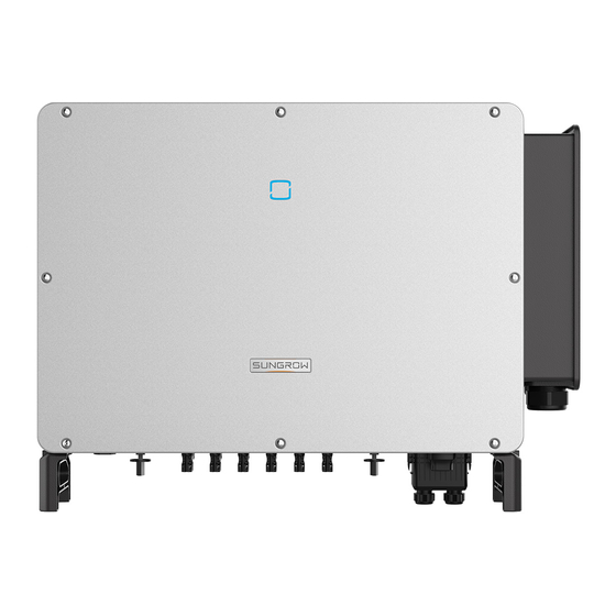
2 Product Description User Manual The following figure shows the common grid configurations. In a TT power grid, the N-PE voltage should be lower than 30 V. Make sure the inverter is applied to an IT system before enabling the Anti-PID function. - Page 19 User Manual 2 Product Description figure 2-2 Inverter Appearance Description Name To indicate the current working state of the inverter. LED indicator AC junction box To connect AC cables in this area. Bottom handles To move the inverter. DC switches, DC terminals, and communication terminals. Wiring area For details, refer to"5.2 Terminal Description"...
-
Page 20: Symbols On Product
2 Product Description User Manual figure 2-3 Product Dimensions(in mm) Symbols on Product Symbol Explanation Do not dispose of the inverter together with household waste. TÜV mark of conformity. CE mark of conformity. EU/EEA Importer. UKCA mark of conformity. Danger to life due to high voltages! Only qualified personnel can open and service the inverter. -
Page 21: Led Indicator
User Manual 2 Product Description LED Indicator The LED indicator on the front of the inverter indicates the working state of the inverter. table 2-1 LED Indicator State Description LED Color State Definition The device is connected to the grid and operating normally. -
Page 22: Function Description
2 Product Description User Manual figure 2-4 Circuit Diagram • DC Switches can safely disconnect the PV input when necessary to ensure the safe op- eration of the inverter and the safety of personnel. • The DC SPD provides a discharge circuit for the DC side overvoltage to prevent it from damaging the internal circuits of the inverter. - Page 23 User Manual 2 Product Description Communication Interface The inverter is designed with standard RS485 communication interfaces. The standard RS485 communication interfaces are used to establish communication con- nection with monitoring devices and upload monitoring data by using communication cables. After communication connection is established, users can view inverter information or set in- verter parameters through the iSolarCloud.
- Page 24 2 Product Description User Manual For negative voltage scheme, after the PID is enabled, the voltage to ground of all PV strings is lower than 0, and therefore the PV string-to-ground voltage is a negative value. • Before enabling the PID recovery function, make sure the voltage polarity of the PV modules to ground meets requirement.
-
Page 25: Unpacking And Storage
• Check the inner contents for damage after unpacking. Contact SUNGROW or the transport company in case of any damage or incompleteness, and provide photos to facilitate services. Do not dispose of the original packing case. It is recommended to store the device in the original packing case when the product is decommissioned. - Page 26 3 Unpacking and Storage User Manual • Do not place the inverter in places with items that may affect or damage the inverter. • Store the inverter in a clean and dry place to prevent dust and water vapor from eroding. •...
-
Page 27: Mechanical Mounting
Mechanical Mounting Respect all local standards and requirements during mechanical installation. Safety During Mounting Make sure there is no electrical connection before installation. Before drilling, avoid the water and electricity wiring in the wall. Poor installation environment will affect system performance! •... -
Page 28: Location Requirements
The ambient temperature and relative humidity must meet the following requirements. • Please consult SUNGROW before installing inverters outdoors in salt stress areas. Salt stress areas mainly refer to coastal areas that are within 500 meters from the coast. The deposition of salt fog varies largely with nearby seawater characteristics, sea wind, pre- cipitation, relative humidity, terrain, and forest coverage. -
Page 29: Carrier Requirements
Install the inverter vertically or at the maximum allowable rear tilt angle. Do not install the in- verter horizontally, forward, excessively backward, sideways, or upside down. Please consult SUNGROW before tilting backwards the inverter and install it in floating power plants. -
Page 30: Clearance Requirements
4 Mechanical Mounting User Manual In case the installation site is a level surface, mount the inverter to the bracket to meet the mounting angle requirements, as shown in the figure below. Take the following items into account when designing the bracket scheme: •... -
Page 31: Installation Tools
User Manual 4 Mechanical Mounting Install the inverter at an appropriate height for ease of viewing LED indicator and operating switch(es). Installation Tools Installation tools include but are not limited to the following recommended ones. If necessary, use other auxiliary tools on site. table 4-1 Tool specification Goggles Earplugs... -
Page 32: Moving Inverter
4 Mechanical Mounting User Manual Rubber mallet Socket wrench set Wrench Wrist strap (16mm) (13 mm, 16 mm) Wire cutter Wire stripper Hydraulic plier Heat gun H4 Plus terminal H4 Plus terminal Multimeter RJ45 crimping tool crimping pliers wrench ≥ 1500 Vdc 4–6mm Vacuum cleaner Moving Inverter... -
Page 33: Manual Transport
User Manual 4 Mechanical Mounting 4.4.1 Manual Transport Lift and move the inverter to the destination by using the side handles and bottom handles. 4.4.2 Hoisting Transport step 1 Release the sealing screws on the mounting lugs and store them properly. Anchor two M12 thread lifting rings to the lugs of the inverter. -
Page 34: Installing Mounting-Bracket
4 Mechanical Mounting User Manual step 4 Remove the lifting rings and reassemble the sealing screws released in Step 1. Keep the inverter balanced throughout the hoisting process and avoid collisions with walls or other objects. Stop hoisting in the event of severe weather, such as heavy rain, thick fog, or strong wind. -
Page 35: Pv Bracket-Mounted Installation
User Manual 4 Mechanical Mounting figure 4-1 Dimensions of Mounting-bracket 4.5.1 PV Bracket-Mounted Installation step 1 Assemble the mounting-bracket. step 2 Level the assembled mounting-bracket by using the level, and mark the positions for drilling holes on the PV bracket. Drill the holes by using a hammer drill. step 3 Secure the mounting-bracket with bolts. -
Page 36: Wall-Mounted Installation
4 Mechanical Mounting User Manual Components Description Spring washer – – Hex nuts - - End 4.5.2 Wall-Mounted Installation step 1 Assemble the mounting-bracket. step 2 Level the assembled mounting-bracket by using the level, and mark the positions for drilling holes. -
Page 37: Installing Inverter
User Manual 4 Mechanical Mounting Components Description – Wall Fastening the bolt in the sequence of nut, spring wash- Expansion bolt er, slat washer Mounting-bracket – - - End Installing Inverter step 1 Take out the inverter from the packing case. step 2 Hoist the inverter to the installation position when necessary (refer to "4.4.2 Hoisting Trans- port"). -
Page 38: Electrical Connection
Electrical Connection Safety Instructions The PV string will generate lethal high voltage when exposed to sunlight. • Operators must wear proper personal protective equipment during electrical connections. • Must ensure that cables are voltage-free with a measuring instrument before touching DC cables. •... - Page 39 User Manual 5 Electrical Connection • Do not damage the ground conductor. Do not operate the product in the ab- sence of a properly installed ground conductor. Otherwise, it may cause per- sonal injury or product damage. • Please use measuring devices with an appropriate range. Overvoltage can dam- age the measuring device and cause personal injury.
-
Page 40: Terminal Description
5 Electrical Connection User Manual • Install the external protective grounding cable first when performing electrical connection and remove the external protective grounding cable last when re- moving the inverter. • Comply with the safety instructions related to PV strings and the regulations re- lated to the utility grid. - Page 41 User Manual 5 Electrical Connection figure 5-1 Terminal Description * The image shown here is for reference only. The actual product received may differ. Item Terminal Mark Note 24, PV connector PV terminals + / - For Communication module connection COM1 (Optional).
-
Page 42: Electrical Connection Overview
5 Electrical Connection User Manual Electrical Connection Overview The electrical connection should be realized as follows: Designation Item PV string Inverter Grid Monitoring device AC circuit breaker table 5-1 Cable Requirements Specification Type Cable Cable Diame- Cross-sectional Area ter(mm) PV cable comply- DC cable ing with 1,500V 5~7.8... -
Page 43: Crimp Ot/Dt Terminal
User Manual 5 Electrical Connection (1) A copper to aluminum adapter terminal is required when an aluminum cable is used. For details, refer to " Aluminum Cable Requirements". table 5-2 PE Wire Requirements PE Wire Cross Note Section The specifications are valid only when the phase wire and PE wire use the same material. -
Page 44: External Protective Grounding Connection
5 Electrical Connection User Manual 1. Heat shrink tubing 2. OT/DT terminal 3. Hydraulic pliers 4. Heat gun Aluminum Cable Requirements If an Aluminum cable is selected, use a copper to Aluminum adapter terminal to avoid direct contact between the copper bar and the Aluminum cable. figure 5-2 Aluminum Cable Connection 1. -
Page 45: External Protective Grounding Requirements
AC side grounding terminal are reliably grounded. The grounding connection can be made by other means if they are in accordance with the local standards and regulations, and SUNGROW shall not be held liable for the possible consequences. -
Page 46: Ac Cable Connection
5 Electrical Connection User Manual step 3 Apply paint to the grounding terminal to ensure corrosion resistance. The grounding screws have been anchored to the side of the inverter before deliv- ery, and do not need to be prepared. There are two grounding terminals. Use one of them to ground the inverter. - - End AC Cable Connection 5.6.1 AC Side Requirements... - Page 47 The apparent power of the inverter should never exceed the power of the transformer. The maximum AC current of all inverters connected in parallel must be taken into ac- count. If more than 30 inverters are connected to the grid, contact SUNGROW. •...
-
Page 48: Requirements For Ot/Dt Terminal
5 Electrical Connection User Manual • When the anti-PID function is enabled, observe the following items: – If the LV side winding is in Y shape, neutral point grounding is prohibited. – Surge protective devices (SPD) for the AC combiner box and on the LV side of the transformer are recommended to be connected in the "3+1"... - Page 49 User Manual 5 Electrical Connection step 3 Loosen the screws of the bottom sealing plate and take out the bottom sealing plate. step 4 Loosen the swivel nut of the AC waterproof connector and select a seal according to the ca- ble outer diameter, remove the inner sealing ring if the cable diameter is larger than 40mm.
- Page 50 5 Electrical Connection User Manual step 6 Open the protection cover. step 7 Strip the protection layer and insulation layer by specific length, as described in the figure below. step 8 Make the cable and crimp OT/DT terminal. step 9 Secure the wires to corresponding terminals. Please fasten AC terminals referring to the tor- que specified on the label inside the AC box.
- Page 51 User Manual 5 Electrical Connection Ensure that the depth L of the socket used is not less than 28mm.
- Page 52 5 Electrical Connection User Manual If the PE cable is an independent single-core cable, it should be inserted into the cabinet through the standby grounding terminal. step 10 Close the protection cover. step 11 Close the wiring compartment and tighten the two screws on its front cover with supplied Al- len wrench.
-
Page 53: Dc Cable Connection
The damage caused by this is not covered by the warranty. • Electric arc or contactor over-temperature may occur if the PV connectors are not firmly in place, and SUNGROW shall not be held liable for any damage caused. •... -
Page 54: Pv Input Configuration
5 Electrical Connection User Manual The following requirements about PV string connection must be met. Otherwise, it may cause irreversible damage to the inverter, which is not covered by the warranty. • Mixed use of PV modules of different brands or models in one MPPT circuit, or PV modules of different orientation or inclination in a string may not damage in- verter, but will cause system bad performance! 5.7.1 PV Input Configuration... -
Page 55: Assembling Pv Connectors
5 Electrical Connection 5.7.2 Assembling PV Connectors SUNGROW provides corresponding PV connectors in the scope of delivery for quick connection of PV inputs. To ensure IP66 protection, use only the supplied connector or the connector with the same ingress of protection. -
Page 56: Installing Pv Connector
5 Electrical Connection User Manual If the PV polarity is reversed, the inverter will be in a fault or alarm state and will not operate normally. - - End 5.7.3 Installing PV Connector step 1 Rotate the DC switch to “OFF” position. step 2 Check the cable connection of the PV string for polarity correctness and ensure that the open circuit voltage in any case does not exceed the inverter input limit of 1,500V. -
Page 57: Communication Junction Box
• Arc or contactor over-temperature may occur if the PV connectors are not firmly connected in place, and SUNGROW shall not be held liable for any damage caused due to this operation. step 4 Follow the foregoing steps to connect PV connectors of other PV strings. -
Page 58: Communication Wiring Board
5 Electrical Connection User Manual Install the Junction Box Align the junction box with the corresponding port and push it into the port to reassemble junction box. Communication Wiring Board The communication board of the inverter includes two layers. The upper layer communica- tion board mainly includes RS485 communication interfaces while the lower layer communi- cation board mainly includes DI/DO interface. -
Page 59: Rs485 Connection
User Manual 5 Electrical Connection 5.10 RS485 Connection 5.10.1 Interface Description As shown in the Figure below, the inverter is equipped with three RS485 communication in- terfaces and one dip switch. All three interfaces can be connected to a data acquisition device (Data Logger), to achieve data exchange with PC or other monitoring devices. - Page 60 5 Electrical Connection User Manual figure 5-4 Single-inverter Connection Multi-inverter Communication System In case of multiple inverters, all the inverters can be connected via RS485 cables in the daisy chain manner. figure 5-5 Multi-inverter Connection When more than 15 inverters are connected to the same daisy chain, in order to ensure the communication quality, the Logger at the first end of the daisy chain needs to be equipped with a terminal resistor of 120Ω, the inverter at the last end needs to be equipped with a RS485-dip switch (SW1), and the shielding layer of the communication cable should be sin-...
-
Page 61: Connection Procedure(Terminal Block)
User Manual 5 Electrical Connection figure 5-6 Configuration of Dip Switch (N≥15) The length of the RS485 cable and twisted pair cable should be no longer than 1,200m. If multiple inverters are connected to the data logger, the number of permissible daisy chains and the number of devices allowed to be connected should meet the requirements (refer to the user manual for the data logger). - Page 62 5 Electrical Connection User Manual Outer Diameter D(mm) Seal 4.5~6 6~12 12~18 step 4 Secure the cable to the terminal base. step 5 Insert the terminal base into the corresponding terminal. table 5-4 Terminal definition Definition RS485 A+ RS485 A+ RS485 B- RS485 B- step 6 If other wiring operations need to be performed on the communication board, finish the wir-...
-
Page 63: Connection Procedure (Rj45 Ethernet Port)
User Manual 5 Electrical Connection - - End 5.10.4 Connection Procedure (RJ45 Ethernet Port) step 1 Remove the communication junction box, see " Remove the Junction Box". step 2 Loosen the swivel nut of the junction box and select an appropriate seal according to cable outer diameter. -
Page 64: Plc Communication Connection
7 Pull the cable gently to make sure it is secured, tighten the swivel nut clockwise. - - End 5.11 PLC Communication Connection With a PLC communication module built inside, the inverter can communicate with the CO- M100A provided by SUNGROW. For specific wiring method, refer to the COM100A user manual. -
Page 65: Dry Contact Connection
• In case of PLC communication, the AC cable must be a multi-core cable. • The COM100A is an optional device that can be ordered from Sungrow. • The COM100A conducts data communication by directly using the AC output cable(L1&L3 wire) of the inverter and thus saves the trouble to lay and main- tain the special communication cables. - Page 66 5 Electrical Connection User Manual figure 5-7 Normally open contact figure 5-8 Normally closed contact Devices connected to the relay should comply with related requirements: AC-Side Requirements DC-Side Requirements Max. voltage: 125Vac Max. voltage: 30Vdc Max. current: 5A Max. current: 5A DI terminal (emergency stop dry contact): the dry contact can be configured to be an emergency stop contact.
-
Page 67: Wiring Procedure
Block)". 5.13 Communication Module Connection (optional) Connect the communication module produced by SUNGROW, such as Eye M4(WiFi) to the communication accessory port. After successful connection, information such as power generation and running state of the inverter can be viewed via the APP on the phone. - Page 68 5 Electrical Connection User Manual For details on module installation and configuration, refer to the manual delivered together with the module.
-
Page 69: Commissioning
Commissioning Inspection Before Commissioning Check the following items before starting the inverter: • All equipment has been reliably installed. • DC switch(es) and AC circuit breaker are in the "OFF" position. • The ground cable is properly and reliably connected. •... - Page 70 6 Commissioning User Manual step 2 Close the AC circuit breaker between the inverter and the grid. step 3 Install the iSolarCloud App, see "7.2 Installing App" for details. step 4 Set initial protection parameters via the iSolarCloud App when the inverter is connected to the grid for the first time (see Step 4 in "7.4.2 Login Procedure"...
-
Page 71: Isolarcloud App
iSolarCloud App Brief Introduction The iSolarCloud App can establish communication connection to the inverter via the Blue- tooth, thereby achieving near-end maintenance on the inverter. Users can use the App to view basic information, alarms, and events, set parameters, or download logs, etc. *In case the communication module Eye, WiFi or WiNet-S is available, the iSolarCloud App can also establish communication connection to the inverter via the mobile data or WiFi, thereby achieving remote maintenance on the inverter. -
Page 72: Function Overview
7 iSolarCloud App User Manual Function Overview The App provides parameter viewing and setting functions, as shown in the following figure. figure 7-1 App Function Tree Map Login 7.4.1 Requirements The following requirements should be met: • The AC or DC side of the inverter is powered-on. •... - Page 73 User Manual 7 iSolarCloud App • Tap "Manual connection" and select "Others" at the bottom of the page, the Bluetooth search page will automatically pop up, and select the inverter to be connected according to the SN on the nameplate on the side of the inverter body. figure 7-2 Bluetooth Connection step 3 Enter the identity verification interface after the Bluetooth connection is established.
- Page 74 If the dis- tributor is unable to provide the required information, contact SUNGROW. step 4 If the inverter is not initialized, you will enter the quick setting interface of initializing protec- tion parameter.
-
Page 75: Home
In some European regions whose grid code complies with EN 50549, select the parameter EN 50549_2 (MV grid-connection). For parameter settings in specific countries, please contact SUNGROW. In the Brazilian region, set the country code as "Brazil". Selecting "Brazil_230" or "Brazil_240"... - Page 76 7 iSolarCloud App User Manual Designation Description Present state of the PID function. For details, refer to "table PID function state 7-3 Description of PID State" Display the PV power generation power, feed-in power, etc. The line with an arrow indicates energy flow between con- Power flow chart nected devices, and the arrow pointing indicates energy flow direction.
-
Page 77: Run Information
User Manual 7 iSolarCloud App table 7-3 Description of PID State Description State PID recovery The inverters perform PID recovery actively. running It is detected that the ISO impedance is abnormal or the PID cannot PID abnormity work normally after the PID function is enabled. If the inverter is running abnormally, the alarm or fault icon will be displayed in the lower right corner of the inverter icon in power flow chart. -
Page 78: Records
7 iSolarCloud App User Manual Classifica- Description Parameter tion Daily Yield Monthly Yield Annual Yield Current active power value of the inverter Total Active Power Current reactive power value of the inverter Total Reactive Power Total Apparent Current apparent power value of the inverter Power Output Total Power Factor... - Page 79 User Manual 7 iSolarCloud App figure 7-7 Fault Alarm Record to select a time segment and view corresponding records. The inverter can record up to 400 latest entries. Select one of the records in the list and tap the record to view the detailed fault information as shown in following figure.
- Page 80 7 iSolarCloud App User Manual figure 7-9 Power Curve The App displays power generation records in a variety of forms, including daily power gen- eration graph, monthly power generation histogram, annual power generation histogram and total power generation histogram. table 7-5 Yield Record Explanation Description Parameter Shows the power output from 5 am to 11 pm in a single day.
-
Page 81: More
User Manual 7 iSolarCloud App More Tap More on the navigation bar to enter the corresponding interface,, as shown in the follow- ing figure. figure 7-10 More 7.8.1 System Parameters Tap Settings→System Parameters to enter the corresponding interface, as shown in the following figure. - Page 82 7 iSolarCloud App User Manual figure 7-12 Running Time PID Parameters Tap Settings→Operation Parameters→PID Parameters to enter the corresponding interface. figure 7-13 PID Parameters table 7-6 PID Parameter Description Description Parameter Enable/Disable the PID night recovery function. Once enabled, it PID Recovery works between 22:00 pm and 5:00 am by default.
-
Page 83: Power Regulation Parameters
User Manual 7 iSolarCloud App figure 7-14 AFCI Setting 7.8.3 Power Regulation Parameters Active Power Regulation Tap Settings→Power Regulation Parameters→Active Power Regulation to enter the screen, as shown in the following figure. figure 7-15 Active Power Regulation table 7-7 Active Power Regulation Definition/Setting Range Parameter... - Page 84 7 iSolarCloud App User Manual Definition/Setting Range Parameter Description Active power decline The decline rate of inverter ac- 3%/min~6000%/min gradient tive power per minute. Active power rising The rise rate of inverter active 3%/min~6000%/min gradient power per minute. Active power setting Switch for enabling/disabling Enable/Disable persistence...
- Page 85 User Manual 7 iSolarCloud App figure 7-16 Reactive Power Regulation table 7-8 Reactive Power Regulation Definition/Setting Range Parameter Description Reactive power genera- Switch for enabling/disabling Enable/Disable tion at night night SVG function. Reactive power ratio at Reactive power ratio set for -100%~0%/ night the night SVG function.
- Page 86 7 iSolarCloud App User Manual Definition/Setting Range Parameter Description QP_P3 Output power at P3 on the Q 20.0%~100.0% (P) mode curve (in percentage) QP_K1 Power factor at P1 on the Q(P) Curve A/Curve mode curve C:0.800~1.000 Curve B: [-0.600~0.600]*Ac- tive Overload Rate/1000 QP_K2 Power factor at P2 on the Q(P) Curve A/Curve C:...
- Page 87 User Manual 7 iSolarCloud App Definition/Setting Range Parameter Description QU_V2 Pre-set grid voltage U2 that is 80.0%~100.0% reactive according to the grid voltage. QU_Q2 Pre-set proportion of reactive [-60.0%~60.0%]* Overload power according to the grid Rate/1000 voltage U2. QU_V3 Pre-set grid voltage U3 that is 100.0%~120.0% reactive according to the grid voltage.
-
Page 88: Communication Parameters
7 iSolarCloud App User Manual figure 7-17 Q(U) Curve figure 7-18 Q(P) Curve 7.8.4 Communication Parameters Serial Port Parameters Tap Settings→Communication Parameters→Serial Port Parameters to enter the corre- sponding interface, as shown in the following figure. figure 7-19 Serial Port Parameters table 7-9 Serial Port Parameters Range Parameter... -
Page 89: Firmware Update
User Manual 7 iSolarCloud App figure 7-20 MPLC Parameters table 7-10 MPLC Parameters Range Parameter Band Num Band1, Band2 Array ID 1–255 Winding ID 1–10 7.8.5 Firmware Update To avoid download failure due to poor on-site network signal, it is recommended to download the firmware package to the mobile device in advance. -
Page 90: Password Changing
7 iSolarCloud App User Manual step 9 Wait for the file to be uploaded. When the upgrade is finished, a message is displayed indi- cating that the upgrade is completed. Tap Complete to end the upgrade. - - End 7.8.6 Password Changing Tap Modify Password to enter the modify password interface, as shown in the following figure. -
Page 91: System Decommissioning
System Decommissioning Disconnecting Inverter Danger of burns! Even if the inverter is shut down, it may still be hot and cause burns. Wear protec- tive gloves before operating the inverter after it cools down. For maintenance or other service work, the inverter must be switched off. Proceed as follows to disconnect the inverter from the AC and DC power sources. -
Page 92: Disposal Of Inverter
8 System Decommissioning User Manual step 1 Refer to "5 Electrical Connection", for the inverter disconnection of all cables in reverse steps. In particular, when removing the DC connector, use an H4PLUS wrench to loosen the locking parts and install waterproof plugs. step 2 Refer to"4 Mechanical Mounting", to dismantle the inverter in reverse steps. -
Page 93: Troubleshooting And Maintenance
App or the LCD. Modify the overvoltage protection values with the con- sent of the local electric power operator. 3. Contact Sungrow Customer Service if the pre- ceding causes are ruled out and the fault persists. Generally, the inverter will be reconnected to the grid after the grid returns to normal. - Page 94 2. Check whether the protection parameters are appropriately set via the App or the LCD. 3. Contact Sungrow Customer Service if the pre- ceding causes are ruled out and the fault persists. Generally, the inverter will be reconnected to the grid after the grid returns to normal.
- Page 95 App or the LCD. 3. Contact Sungrow Customer Service if the pre- ceding causes are ruled out and the fault persists. 1. Check whether the corresponding string is of reverse polarity.
- Page 96 3. Check if the DC fuse is damaged. If so, replace Alarm the fuse. 4. Contact Sungrow Customer Service if the pre- ceding causes are ruled out and the alarm persists. *The code 548 to code 563 are corresponding to string 1 to string 16 respectively.
- Page 97 If so, replace the dam- aged cable and secure terminals to ensure a reli- able connection. 5. Contact Sungrow Customer Service if the pre- ceding causes are ruled out and the fault persists. 1. Check whether the AC cable is correctly connected.
- Page 98 2. Reconnect the communication cable of the cation Abnormal meter. Alarm 3. Contact Sungrow Customer Service if the pre- ceding causes are ruled out and the alarm persists. 1. Check whether the output port is connected to actual grid. Disconnect it from the grid if so.
- Page 99 Close the AC and DC switches in turn 15 248–255, 300– minutes later and restart the system. 322, 324–328, 3. Contact Sungrow Customer Service if the pre- 401–412, 600– ceding causes are ruled out and the fault persists. 603, 605, 608, 612, 616, 620, 622–624, 800,...
- Page 100 Close the AC and DC switches in turn 15 364-395 minutes later and restart the system. Overvoltage Fault 2. If the fault persists, please contact Sungrow Power Customer Service. 1. Check whether the number of PV modules of the corresponding string is less than other strings.
-
Page 101: Maintenance
DC side current drops below 0.5 A. 3. It is prohibited to power up the inverter again. Please contact Sungrow Customer Service. Contact SUNGROW if the measures listed in the “Troubleshooting Method” col- umn have been taken but the problem persists. Maintenance 9.2.1 Maintenance Notices... - Page 102 To avoid the risk of electric shock, do not perform any other maintenance opera- tions beyond this manual. If necessary, contact SUNGROW for maintenance. Oth- erwise, the losses caused is not covered by the warranty.
-
Page 103: Routine Maintenance
User Manual 9 Troubleshooting and Maintenance 9.2.2 Routine Maintenance Item Method Period Six months to a year Check the temperature and dust of the inverter. Clean the inverter enclosure if Device clean (depending on the dust con- necessary. tents in air) Check whether all cable are firmly con- nected in place. - Page 104 9 Troubleshooting and Maintenance User Manual step 3 Press the tab of the latch hook, unplug the cable connection joint outwards, and loosen the screw on the fan holder. step 4 Pull out the fan module, clean the fans with soft brush or vacuum cleaner, and replace them when necessary.
-
Page 105: Appendix
10 Appendix 10.1 Technical Data Parameters SG125HX Input (DC) Max. PV input voltage 1500 V Min.PV input voltage / Startup in- 500 V / 550 V put voltage Nominal input voltage 1160 V MPP voltage range 500 V ~ 1500 V... -
Page 106: Wring Distance Of Di Dry Contact
Grid Support power control and power ramp rate control * Only compatible with Sungrow Logger, EyeM4 and iSolarCloud. 10.2 Wring Distance of DI Dry Contact The wiring distance between DI dry contact terminals must meet the requirements in the ta-... - Page 107 User Manual 10 Appendix refers to the cable length in one direction between the DI dry contact terminal of the k verter and the corresponding terminal of the (k-1) inverter. table 10-1 Correspondence Between Inverter Quantity and Maximum Wiring Distance Maximum Wiring Distance(unit:m) Number of Inverter...
-
Page 108: Quality Assurance
• The customer shall give SUNGROW a reasonable period to repair the faulty device. Exclusion of Liability In the following circumstances, SUNGROW has the right to refuse to honor the quality guarantee: • The free warranty period for the whole machine/components has expired. - Page 109 User Manual 10 Appendix We need the following information to provide you the best assistance: • Model of the device • Serial number of the device • Fault code/name • Brief description of the problem For detailed contact information, please visit: https://en.sungrowpower.com/contactUS.
Need help?
Do you have a question about the SG125HX and is the answer not in the manual?
Questions and answers