Sungrow SG125HV User Manual
Pv grid-connected
Hide thumbs
Also See for SG125HV:
- User manual (112 pages) ,
- Quick installation manual (16 pages) ,
- Installation manual (6 pages)

Related Manuals for Sungrow SG125HV


Summary of Contents for Sungrow SG125HV
- Page 1 User Manual SG125HV SG125HV-20 PV Grid-connected Inverter SG125HV-V1-UEN-Ver10-201809 Version: 1.0...
- Page 3 About This Manual This manual is for the SG125HV/SG125HV-20, a three-phase PV grid-connected transformerless inverter, (hereinafter referred to as inverter unless otherwise specified). The inverter is grid-connected, transformer-less, robust and of high conversion efficiency. This manual contains information about the inverter, which will provide guidelines on connecting the inverter into the PV power system and how to operate the inverter.
- Page 4 Symbols Explanation Important instructions contained in this manual should be followed during installation, operation and maintenance of the inverter. They will be highlighted by the following symbols. DANGER indicates a hazard with a high level of risk which, if not avoided, will result in death or serious injury.
- Page 5 Symbols on the Inverter Body WARNING: ELECTRIC SHOCK HAZARD. THE DC CONDUCTORS OF THIS PHOTOVOLTAIC SYSTEM ARE UNGROUNDED AND MAY BE ENERGIZED. WARNING: Electric Shock Hazard. The DC conductors of this photovoltaic system are normally ungrounded but will become intermittently grounded without indication when the inverter measures the PV array isolation.
- Page 6 WARNING: ELECTRIC SHOCK AVERTISSEMENT: RISQUE DE CHOC HAZARD. THE DC CONDUCTORS OF ÉLECTRIQUE. LES CONDUCTEURS DC THIS PHOTOVOLTAIC SYSTEM ARE DE CE SYSTÈME PHOTOVOLTAÏQUE NE UNGROUNDED SONT PAS MIS À LA TERRE ET ENERGIZED. PEUVENT ÊTRE MIS SOUS TENSION. WARNING: Electric Shock Hazard. The AVERTISSEMENT: Risque choc...
- Page 7 CAUTION: Check user manual before ATTENTION: Vérifier manuel service. d'utilisateur avant l’utilisation.
-
Page 8: Table Of Contents
Contents About This Manual ..............I Safety Instructions .............. 1 Product Description ............13 Intended Usage ....................13 Product Introduction ..................14 2.2.1 Model Description ................... 14 2.2.2 Appearance ......................15 2.2.3 Dimensions ......................16 2.2.4 LED Indicator Panel ..................16 2.2.5 DC Switch ...................... - Page 9 Installation Tools .................... 35 Installing the Inverter ................... 35 5.4.1 Installing to Metal Frame ................36 5.4.2 Installing to Concrete Wall ................38 Electrical Connection ............41 Terminal Description ..................41 6.1.1 Appearance ......................41 6.1.2 Dimensions of Terminal ................. 43 AC Side Cable Connection .................
- Page 10 Troubleshooting and Maintenance ......... 70 Troubleshooting ..................... 70 Maintenance ....................79 9.2.1 Routine Maintenance ..................79 9.2.2 Maintenance Instruction ................79 10 SunAccess APP ..............82 10.1 Introduction to the System ................ 82 10.2 Acquire and install SunAccess APP ............82 10.2.1 Installation Condition ..................
- Page 11 11.4 Contact Information ...................109...
-
Page 13: Safety Instructions
1 Safety Instructions The inverter has been designed and tested according to strict international safety regulations. As electrical and electronic equipment, safety instructions related to them must be complied with during installation, commissioning, operation and maintenance. Incorrect operation or work may result in damage The property safety of the operator or a third party ... - Page 14 1 Safety Instructions User Manual If there is visible damage to the packaging or the inner contents, or if there is something missing, contact Sungrow or the forwarding company. There is a risk of injury due to improperly handling the device! ...
- Page 15 Operate the inverter by strictly following the descriptions in this manual to avoid unnecessary personal injury and property damage. Arc flash, fire or explosion may occur if done otherwise and Sungrow will hold no liability for damages. The following improper operations can cause an arc flash, fire and explosion inside the device.
- Page 16 1 Safety Instructions User Manual inside the device that may be alive; The power cable connection is loose; Spare parts, such as bolts, are falling inside the inverter; Incorrect operation by unqualified persons that have not received training;...
- Page 17 Do not replace the inverter internal components without permission. Damage to the inverter may occur and it may void any or all warranty rights from Sungrow. There is a risk of inverter damage due to electrostatic discharge! The printed circuit boards contain components sensitive to electrostatic discharge.
- Page 18 1 Safety Instructions User Manual Respect the following regulations: Grid-connection regulations; Safety instructions related to PV arrays; Safety instructions related to other electrical devices. Consignes de Sécurité L'onduleur a été conçu et testé selon les règles de sécurité internationales strictes.
- Page 19 L'appareil est soigneusement testé et strictement inspecté avant la livraison. Des dégâts peuvent survenir lors de l'expédition. S'il y a des dommages visibles à l'emballage ou au contenu interne, ou s'il y a quelque chose qui manque, contacter Sungrow ou la société d'expédition. ATTENTION ...
- Page 20 évitables aux personnes et des dommages à l'appareil. Un arc électrique, un incendie ou une explosion peuvent se produire si cela s'effectue autrement et Sungrow ne sera responsable des dommages. AVERTISSEMENT Les opérations incorrectes suivantes peuvent provoquer un arc électrique, un incendie et une explosion à...
- Page 21 User Manual 1 Safety Instructions personnel qualifié. Une mauvaise manipulation de ces accidents peut entraîner une faute ou un accident plus grave. Brancher et débrancher le fusible HT côté DC lorsqu'il est sous tension; Toucher la fin des câbles qui n'ont pas d'isolation et qui peuvent encore être sous tension;...
- Page 22 Ne pas remplacer les composants internes de l'onduleur sans autorisation. Des dommages à l'onduleur peuvent se produire et il peut annuler tout ou partie des droits de garantie de Sungrow. Il y a un risque de dommages causés par l'onduleur en raison de décharges électrostatiques!
- Page 23 User Manual 1 Safety Instructions HAZARD. THE DC CONDUCTORS OF ÉLECTRIQUE. LES CONDUCTEURS DC THIS PHOTOVOLTAIC SYSTEM ARE DE CE SYSTÈME PHOTOVOLTAÏQUE NE UNGROUNDED SONT PAS MIS À LA TERRE ET ENERGIZED. PEUVENT ÊTRE MIS SOUS TENSION. WARNING: Electric Shock Hazard. The AVERTISSEMENT: Risque choc...
- Page 24 1 Safety Instructions User Manual service. d'utilisateur avant l’utilisation.
-
Page 25: Product Description
2 Product Description 2.1 Intended Usage SG125HV/SG125HV-20; a transformerless three-phase PV grid-connected inverter, is an integral component in the PV power system. The inverter is designed to convert the direct current power generated from the PV modules into grid-compatible AC current and feeds the AC current to the utility grid. -
Page 26: Product Introduction
2 Product Description User Manual TN-S TN-C TN-C-S Transformer Transformer Transformer SG125HV/ SG125HV/ SG125HV/ SG125HV-20 SG125HV-20 SG125HV-20 Transformer Transformer SG125HV/ SG125HV/ SG125HV-20 SG125HV-20 If the Anti-PID function is to be enabled ensure that: The inverter is applied in the IT system. -
Page 27: Appearance
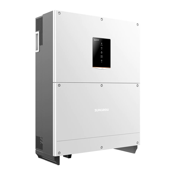
User Manual 2 Product Description Tab. 2-1 Version difference Model PID function Night SVG function SG125HV Optional SG125HV-20 2.2.2 Appearance Fig. 2-2 Appearance * Pictures are indicative only. Product in kind prevail. Name Description HMI interface to indicate the present working LED indicator panel state of the inverter. -
Page 28: Dimensions
2 Product Description User Manual 2.2.3 Dimensions 296mm 670mm(26.4inch) (11.7inch) Fig. 2-3 Dimensions of the inverter 2.2.4 LED Indicator Panel As an HMI, the LED indicator panel on the inverter front panel indicates the present working state of the inverter. Fig. - Page 29 User Manual 2 Product Description Tab. 2-2 LED indicator description LED indicator LED color LED state Definition The Bluetooth communication is connected, the communication channel has no data interaction Bluetooth No device connected to the Blue inverter through the Bluetooth. The Bluetooth communication is Periodical connected and there is data...
-
Page 30: Dc Switch
2 Product Description User Manual LED indicator LED color LED state Definition grid and operating normally 2.2.5 DC Switch The DC switch is used to disconnect the DC current safely whenever necessary. The inverter operates automatically when input and output requirements are met. -
Page 31: Function Description
DC SPD DC Bus Inverter Circuit AC SPD Switch (DC/AC) Fig. 2-5 Circuit diagram of SG125HV/SG125HV-20 2.3.2 Function Description Inversion function The inverter converts the DC current into grid-compatible AC current and feeds the AC current into the grid. -
Page 32: Derating
2 Product Description User Manual − Anti-PID function (Optional) − PID recovery function (Optional) − Night SVG function (Optional) 2.3.3 Derating Output derating is a way to protect the inverter from overload or potential faults. Situations requiring inverter power derating are: Ambient temperature is too high ... - Page 33 User Manual 2 Product Description =860V =1050V =1250V Ambient temperature[℃] Fig. 2-6 Over-temperature Derating(Pf=1) Lower limit of the over-temperature derating: about 50% of the nominal power. When both the module temperature and the internal temperature meet the derating condition, inverter limits its power according to the lower power limit value of the two.
- Page 34 2 Product Description User Manual grid 570V × kVA V ≤ < grid grid 570V 600V × ≤ ≤ grid 600V ≤ ≤ grid Vgrid [V] Fig. 2-7 Grid under-voltage derating(Pf=1) High input voltage derating If the input voltage is too high, the inverter may derate the power output.
-
Page 35: Pid Function
User Manual 2 Product Description 2.3.4 PID Function SG125HV/SG125HV-20 provides Anti-PID function and PID Recovery function, and achieves raising the potential between the negative electrode of PV array and earth by using internal PID function module. PV Strings Raise the potential between the negative... -
Page 36: Installation Flow
3 Installation Flow Fig. 3-1 shows the installation flow of the inverter and Tab. 3-1 gives a detailed explanation. Start Select mounting location Move inverter Unpacking and Inspection Read User Manual Install inverter Electrical connection Check before commissioning Commissioning Troubleshooting Success? Fig. - Page 37 User Manual 3 Installation Flow Tab. 3-1 Description of installation flow Procedure Description Reference Select optimal installation site Move the inverter to the installation site Unpacking and inspection Read the User Manual, especially the section on “Safety Instruction” Install the inverter to the selected installation site Electrical connection;...
-
Page 38: Unpacking And Storage
Check the inner contents for damage after unpacking. In case any damage is found, please contact Sungrow or the forwarding company. Do not dispose of the original packaging. It is best to store the inverter in its original packaging. -
Page 39: Identifying Inverter
The nameplate is attached to one side of the inverter and the packaging carton separately. It provides information on type of inverter, important specifications, marks of certification institutions, and serial number which are available and identified by Sungrow. Take SG125HV as an example: 光伏并网逆变器 GRID-CONNECTED PV INVERTER Model 型号... -
Page 40: Scope Of Delivery
4 Unpacking and Storage User Manual Tab. 4-1 Description of Icons on the Nameplate Icon Description CSA mark of conformity. The inverter is in compliance with directives of US and CAN. 253758 TUV mark of conformity. The inverter is in compliance with directives of TUV. CE mark of conformity. -
Page 41: Inverter Storage
4.4 Inverter Storage Proper storage is required if the inverter is not installed immediately. Sungrow shall hold no liability for the damage of the device, in appearance or the failure of internal components, caused by improper storage of the device as specified in this manual. - Page 42 4 Unpacking and Storage User Manual If the inverter has been stored more than half a year, the qualified persons should thoroughly check and test it before using.
-
Page 43: Mechanical Installation
5 Mechanical Installation 5.1 Installation Site Selection Select an optimal installation site for safe operation, long service life and outstanding performance. Take the load capacity of the wall into account. The wall (concrete wall or metal frame) should be strong enough for the weight of the inverter over a long period. - Page 44 75°, install the inverter on the frame to meet the requirement for installation angle. The frame and the inverter are installed as shown in the following figure. Frame Installation complete For detailed frame installation solution, contact Sungrow.
- Page 45 User Manual 5 Mechanical Installation With an IP65/NEMA 4X protection rating, the Max. ambient inverter can be installed both outdoors and temperature: 60℃( +140°F) indoors. To achieve better running effect The ambient Min. ambient temperature should be within -25℃…60℃ temperature: -25℃(-13°F) (-13°F to 140°F).
-
Page 46: Moving Inverter To Installation Site
5 Mechanical Installation User Manual Stack installation Triangle installation When the devices are installed back to back, make sure the clearance in between is greater than or equal to 100mm (3.9inch). ≥100mm(3.9inch) Do not install the inverter in a confined space. ... -
Page 47: Installation Tools
User Manual 5 Mechanical Installation the installation site. Follow the instructions below as you move the inverter: Always be aware of the weight of the inverter. Lift the inverter by grasping the handles on both sides of the inverter. ... -
Page 48: Installing To Metal Frame
5 Mechanical Installation User Manual 518mm (20.4inch) 2-M4×10 460mm (18.1inch) 558mm 32mm (22inch) (1.3inch) Fig. 5-1 Dimensions of the bracket (figures in inch) The stainless fasteners are supplied for attaching the bracket to metal frame. 45mm(1.77inch) Fig. 5-2 Dimensions of fastener for metal frame (figures in mm) To install the inverter to concrete walls, the user needs to purchase expansion bolts with proper size (recommended: M10*65) to attach the bracket to concrete walls. - Page 49 User Manual 5 Mechanical Installation Secure the bracket to the metal frame firmly with the supplied fastener. Step 5 The torque of the fasten nut is 35 Nm. Install backplate Name Description Hexagon nut Spring washer Flat washer Screw bolt M10*45 Metal frame Bracket...
-
Page 50: Installing To Concrete Wall
5 Mechanical Installation User Manual 5.4.2 Installing to Concrete Wall Remove the bracket and corresponding fasteners from the packaging. Step 1 Place the bracket on the chosen concrete wall and adjust it to proper Step 2 position and height. Mark the position for holes, drilling according to the hole positions of the Step 3 bracket. - Page 51 User Manual 5 Mechanical Installation If the installation location is lower, the inverter can be directly linked to the bracket, please follow step 6 and then jump to Step If the installation location is higher, the inverter can not be directly linked to the bracket, please perform steps 7 to 10.
- Page 52 5 Mechanical Installation User Manual Please keep the inverter balanced during the whole process of inverter lifting. Inverter may hit the wall or other obstacles if you’re not careful. Fit the inverter to the bracket, refer to step 6. Step 9 After you fit the inverter to the bracket, fasten the inverter to the Step 10 bracket with two M4×16 screws.
-
Page 53: Electrical Connection
6 Electrical Connection Once the inverter is secured to the installation site, it can be connected to the PV system. All electrical connections must comply with local regulations and related electrical rules. Improper cable connection may lead to a fatal injury or permanent damage to the device. - Page 54 6 Electrical Connection User Manual L1 L2 L3 Front view Bottom view Fig. 6-1 Cable connection area *Pictures are indicative only. Please in kind prevail. Name Description Protective components safely DC switch disconnect DC side current. Communication cable connection and Configuration circuit board configuration DC crimping terminal...
- Page 55 User Manual 6 Electrical Connection Name Description DC PE cable access, M6 × 16 (right) or DC PE terminal M10X30 (left)fastening screws Waterproof air valve For Communication cable connection Communication cable Knockout diameter for communication gland cable is 28.5mm. For DC cable connection Knockout diameter for DC cable is 75.8mm.
-
Page 56: Dimensions Of Terminal
6 Electrical Connection User Manual 拧掉格兰头(扳手*2,开口 86mm) Step 2 孔径:75.8mm/2.98in 6.1.2 Dimensions of Terminal Before selecting the cable side terminals, please notice the dimensions of the AC & DC terminals specified in the figure to make sure the selected terminals are proper. -
Page 57: Ac Side Cable Connection
The ultimate short-circuit breaking capacity of the AC circuit breaker determined according on-site transformer configuration and system solution. If there are any problems, please contact Sungrow to confirm the technical solution. It is not allowed to install more than one inverter per fuse or circuit breaker. - Page 58 HV side is connected to the MV grid, please respect following requirement: When more than 25 inverters are connected to a single winding of the transformer, please contact Sungrow to confirm the technical solution. LV side HV side...
- Page 59 fully relies on inverter protection to shut down during the loss of phase fault at the utility side, Sungrow recommends a transformer with a DELTA connection on the utility side. The transformer must be suitable for operation with inverters which work ...
-
Page 60: Grid Connection
6 Electrical Connection User Manual 500V 500V 500V 750V Fig. 6-3 The schematic diagram of AC SPD 6.2.2 Grid Connection The AC terminal block is on the bottom of the inverter. AC connection is the three-phase-three-wire grid +PE connection (L1, L2, L3 and PE). AC Cable Requirements Select AC cables according to the following factors: Grid impedance complies with the specifications below to avoid accidental... - Page 61 User Manual 6 Electrical Connection UV resistance and so on. The maximum operation temperature of the cable should no less than 90° C(+194°F). The current rating of the cable should be selected in accordance with the maximum AC output current of the inverter. The voltage rating of the cable should be no less than 600Vac.
- Page 62 6 Electrical Connection User Manual Connecting the Inverter to Grid High voltage inside the inverter! Ensure all cables are voltage-free before electrical connection. Do not connect the AC circuit breaker until all inverter electrical connections are completed. Disconnect AC circuit breaker to prevent it from inadvertently Step 1 reconnecting.
- Page 63 User Manual 6 Electrical Connection Insert the end of the AC cable into the crimping lug that matches with Step 5 the M10 bolt and tighten it with proper tool. B=E±3mm Fig. 6-4 Crimping the lugs Install the heat-shrinkable tubing. Step 6 Connect the AC cable to the corresponding terminals.
-
Page 64: Connecting Inverter To Pv Arrays
6 Electrical Connection User Manual in case of land subsidence is avoided. Screw cap-nut tightly onto the cable. Step 8 Seal the gaps between the AC cable and the gland inside the lower part Step 9 of the cabinet with duct seal. Seal the gap between the cable and the gland conduit with duct seal or other suitable materials to prevent the entry of foreign bodies or... -
Page 65: Pv Input Connection
String #N ● ● ● The SG125HV/SG125HV-20 is a single stage inverter with only one MPPT. To make full use of the DC input power and reduce the power loss caused by mismatch, the type and rating of the PV modules connected to one inverter should be the same, including: ... - Page 66 6 Electrical Connection User Manual The current rating of the cable should be selected in accordance with the maximum short circuit current of the PV arrays connected to the inverter. The voltage rating of the cable should no less than 1500V. ...
- Page 67 User Manual 6 Electrical Connection Do not connect the AC circuit breaker before electrical connection is completed. Rotate the DC switch to the “OFF” position. Step 1 Strip the insulation layer of the DC cable to Step 2 proper length according to the DC cable specification.
- Page 68 Once positive and negative inputs are short-circuited, it can cause unrecoverable damage to the inverter. Sungrow shall hold no liability for any possible consequences caused by ignorance of this warning. Check the positive and negative polarity of the PV cells. After confirmation, you can insert the DC connectors into the input terminals on the bottom of the inverter.
-
Page 69: Grounding The Inverter
User Manual 6 Electrical Connection moisture and ensure long-term and normal operation of the inverter. 6.4 Grounding the Inverter Due to the transformer-less design of the inverter, neither the DC positive pole nor the DC negative pole of the PV string can be grounded. -
Page 70: Second Protective Earth Terminal
6 Electrical Connection User Manual Inverter 1 Inverter 2 Inverter n PV Arrays 1 PV Arrays 2 PV Arrays n Mounting Frame of PV arrays Equipotential cable Grounding of PV Power System L2 L3 AC Circuit Breaker Inverter AC Grounding Electrode Grounding of Inverter AC Side Fig. -
Page 71: Rs485 Communication Connection
User Manual 6 Electrical Connection The connection of second PE terminal is optional. Whether to connect the terminal is determined according to local standards or regulations, but connection is recommended. Cable Connection Item Name Description Screw M6×12mm Lock washer Washer Cable socket Grounding cable*... -
Page 72: Rs485 Communication System
6 Electrical Connection User Manual 120Ω terminating resistor switch Configuration circuitboard RS485_2 ALARM RS485_1 COM1 COM1 NC1 NO1 PGND DIN1 PGND DIN1 LOCAL STOP Fig. 6-8 Communication configuration The inverter operation information can be transferred to the PC of the installed monitoring software or to a local data logging device through RS485 communication connection. - Page 73 User Manual 6 Electrical Connection Inverter RS485 cable Ethernet cable RS485-2 Data Logger RS485 Ethernet Ethernet port terminal terminal RS485 Communication of inverter Communication Terminating Inverter connection (RS485 Resistor connection) Only out 120ohm Single inverter For Multiple Inverters Where there is more than one inverter, all inverters can be connected in a daisy chain through an RS485 communication cable.
-
Page 74: Rs485 Communication Connection
6 Electrical Connection User Manual Inverter 1 Inverter 2 Inverter n RS485 cable RS485-2 RS485-2 RS485-2 Ethernet cable Data Logger 120Ω RS485 Ethernet Ethernet port terminal terminal Shielding layer is grounded Multiple inverters in daisy chain Communication Terminating Resistor Inverter connection (RS485 n≤15... - Page 75 User Manual 6 Electrical Connection Strip off the insulation layer of the communication cable. Connect the A Step 2 and B of RS485 communication cable to corresponding terminals according to the marks on the configuration circuit board. According to the position of the inverter (refer to the prior section), Step 3 repeat step 1…2 to connect the other RS485 cables.
-
Page 76: Configurable Dry Contact
6 Electrical Connection User Manual Logger 3000 is optional parts and can be ordered from Sungrow. 6.6 Configurable Dry Contact There are Fault Alarm dry contacts and Local Stop dry contacts located on the configurable circuit board. RS485_2 ALARM RS485_1... - Page 77 User Manual 6 Electrical Connection The dry contacts only support passive switch signal input. Multiple inverters connected in a daisy chain topology Inverter N Inverter1 Inverter2 LOCAL STOP LOCAL STOP LOCAL STOP PGND DIN1 PGND DIN1 PGND DIN1 PGND DIN1 PGND DIN1 PGND DIN1 Fig.
-
Page 78: Commissioning
7 Commissioning Commissioning is a critical procedure for a PV system, which can protect the system from fires, and personnel from injury and electrical shock. 7.1 Inspection before Commissioning Before starting the inverter, you should check the following items. The inverter should be accessible for operation, maintenance and service. - Page 79 User Manual 7 Commissioning device is initialized, send start instructions via the App For details, please refer to “10.3 Logging SunAccess APP”. Provided there is sufficient sunlight: PV arrays initialize and supply DC power to inverter; DC-link starts to charge and check the state of the utility grid; ...
-
Page 80: Disconnecting, Dismantling And Disposing The Inverter68
8 Disconnecting, Dismantling and Disposing the Inverter 8.1 Disconnecting the Inverter For maintenance work or any service work, the inverter must be switched off. During normal operation, the inverter should remain switched on. Proceed as follows to disconnect the inverter from DC and AC power sources Disconnect the external AC circuit breaker or disconnect to prevent it Step 1 from accidentally reconnecting to the utility grid. -
Page 81: Disposal Of The Inverter
User Manual 8 Disconnecting, Dismantling and Disposing the Inverter If the inverter will be reinstalled in the future, please refer to “4.4 Inverter Storage” for a proper storage. 8.3 Disposal of the Inverter System owners and the O&M company are responsible for the disposal of the inverter. -
Page 82: Troubleshooting And Maintenance
Sungrow Service. Transient overvoltage, Generally, inverter will transient grid reconnected to the grid after the grid voltage is higher than returns to normal. If the fault occurs the standard value. repeatedly, contact Sungrow Service. - Page 83 006-007 exceeds upper returns to normal. If the fault occurs limit of the inverter. repeatedly, contact Sungrow Service. Grid overfrequency, Generally, inverter will Grid frequency reconnected to the grid after the grid...
- Page 84 4. Check whether the AC circuit breaker is connected. 5. If the fault is not caused by the foregoing reasons and still exists, contact Sungrow Service. 1. The fault is caused by external fault DC component in the of the inverter. Generally, the inverter...
- Page 85 4. If the fault is not caused by the foregoing reasons and still exists, contact Sungrow Service. Output overload, configured Wait for the inverter to return to module power normal. excessively large and If the fault still exists, contact Sungrow normal Service. operation range of the inverter.
- Page 86 AC and DC switches the modules 15 minutes later to restart the inverter. If the fault still exists, contact Sungrow Service. Wait for the inverter to return to normal. Disconnect the AC and DC switches,...
- Page 87 Disconnect the AC and DC switches, Device anomaly and reconnect the AC and DC switches 15 minutes later to restart the inverter. If the fault still exists, contact Sungrow Service. Wait for the inverter to return to normal. If the fault occurs repeatedly: 1.
- Page 88 Device anomaly and reconnect the AC and DC switches 053-060 15 minutes later to restart the inverter. If the fault still exists, contact Sungrow Service. 1. Check whether the fans operate normally and are blocked by sundries. If they are blocked, clear the sundries.
- Page 89 078-081 Device anomaly and reconnect the AC and DC switches 15 minutes later to restart the inverter. If the fault still exists, contact Sungrow Service. AFD module anomaly 1. Check whether the cable connection on the DC side is normal, and take Electric arc fault correction measures if necessary.
- Page 90 532-547 Reverse string polarity 2. If the fault is not caused by the foregoing reasons and still exists, contact Sungrow Service. *The code 532 to code 547 are corresponding to string 1 to string 16 respectively. 1. Check whether the corresponding module is sheltered.
-
Page 91: Maintenance
2. Check the module for abnormal aging. String output current 580-581 3. If the fault is not caused by the anomaly foregoing reasons and still exists, contact Sungrow Service. *The code corresponding to string 17 and string 18 respectively. 9.2 Maintenance 9.2.1 Routine Maintenance... - Page 92 9 Troubleshooting and Maintenance User Manual efficiency may decrease. Therefore, it is necessary to clean the dirty fans and replace the broken fans in time. Stop the inverter and disconnect it from all power supplies before maintenance. Lethal voltage still exists in the inverter even after the inverter has been switched off and disconnected.
- Page 93 User Manual 9 Troubleshooting and Maintenance Step 8 当侧面距离不够时(400~600mm),可将风 扇导轨中间的螺钉拆掉,先卸下第一节风 扇。 Remove all the fans from the inverter. Step 9 Clean the fan with soft brush or vacuum cleaner, or replace the broken Step 10 fans. Reassemble the fans back into the inverter and restart the inverter. Step 11 Cleaning Air Inlet and Outlet A huge amount of heat is generated in the process of running the inverter.
-
Page 94: Sunaccess App
10 SunAccess APP 10.1 Introduction to the System By establishing a communication connection with the inverter through Bluetooth, the SunAccess APP can access near-end maintenance to the inverter. You can check the running info, alarms and events, set the parameters, download the logs and update the firmware through the APP. -
Page 95: Log Into Sunaccess App
User Manual 10 SunAccess APP install the app according to the tips of the interface. For Android: search for the SunAccess in Myapp or Google Play; download and install the app according to the instructions. Click “Open” after the app is installed to open the app. You can also open Step 2 the app by clicking the icon of the app on your phone desktop. - Page 96 10 SunAccess APP User Manual Select the Bluetooth device to be connected according to the serial Step 2 number on the nameplate attached to the inverter side, and establish the connection. Default username: user. Input the password 111111 and click Login. Step 3 Fig.
- Page 97 User Manual 10 SunAccess APP If the inverter is not initialized, you will enter the initialization protection Step 4 parameter quick setting interface as shown in Fig. 10-3 after the Bluetooth is connected. After setting the quick setting interface, click “Save”...
-
Page 98: Homepage
10 SunAccess APP User Manual Fig. 10-4 Homepage 10.4 Homepage Click the “Home” icon from the navigation bar; Step 1 The homepage with the power, power yields, and real-time alarm info will Step 2 appear as shown in Fig. 10-5. - Page 99 User Manual 10 SunAccess APP Date and time Inverter State PID Funtion State Power yield Present Power Power Curve Navigation bar Fig. 10-5 Check the homepage info Tab. 10-1 Description of inverter state State Description After being energized, inverter tracks the PV arrays’ maximum power point (MPP) and converts the DC power into AC power.
-
Page 100: Run Info
10 SunAccess APP User Manual Tab. 10-2 Description of PID function state State Description recovery The inverters perform PID recovery actively. running protection The inverter is suppressing the PID effect. running It is detected that the ISO impedance is abnormal or the PID PID abnormity function cannot work normally after the PID function enabled. - Page 101 User Manual 10 SunAccess APP Fig. 10-6 Run info Tab. 10-3 Description of Running Parameters Parameter Description Total DC power(kW) the total PV input power Input DC voltage(V) the input voltage DC current(A) the input current AC frequency(Hz) Total active power(kW) Output Apparent power(kVA) Monthly...
-
Page 102: History Record
10 SunAccess APP User Manual Parameter Description In parallel resistance to ground (kΩ) Other Countries info Inverter selected country code Inverter selected command Command info information 10.6 History Record Click the “History” icon from the navigation bar to view the history record interface as shown in Fig. - Page 103 User Manual 10 SunAccess APP Fig. 10-8 Fault alarm records If you need to check the alarm records within a certain period of time, please click the time selection bar on the top of the interface to select a certain period of time. The inverter can at most, record the latest 100 fault alarm instances.
-
Page 104: Power Yields Records
10 SunAccess APP User Manual 10.6.2 Power Yields Records User can view various energy records: power curve, daily energy histogram, daily energy histogram, monthly energy histogram, and annual energy histogram. Tab. 10-4 Explanation of power yields records Parameter Description Show the power output from 5 am to 11 pm in a single day. Power curve Each point in the curve is the percentage of present power and nominal power. -
Page 105: Event Records
User Manual 10 SunAccess APP Fig. 10-11 Power curve Swipe left to check the power yields histogram as shown in Fig. 10-12. Step 3 Fig. 10-12 power yields histogram 10.6.3 Event Records Click the “Event records” to check the event record list as shown in Fig. 10-13. -
Page 106: More
10 SunAccess APP User Manual Fig. 10-13 Event records If you need to check the event records within a certain period of time, please click the time selection bar on the top of the interface to select a certain period of time. The inverter can at most record the latest 100 events. -
Page 107: Power On/Power Off
User Manual 10 SunAccess APP Fig. 10-14 More 10.7.1 Power On/Power Off Click “Power on”/”Power off” and click “Confirm” in the dialog box popped out to start or stop the inverter as shown in Fig. 10-15. Fig. 10-15 Power on... -
Page 108: System Parameters
10 SunAccess APP User Manual 10.7.2 System Parameters Click the “System parameters” to check the system parameter info and set the related parameters as shown in Fig. 10-16. Fig. 10-16 System parameter Tab. 10-5 Explanation of system parameters Parameter Description Date Setting Time deviation between the time on the inverter and the local time of the installation site may cause data logging... -
Page 109: Operation Parameters
User Manual 10 SunAccess APP 10.7.3 Operation Parameters Click the “Operation parameters” to check the operation parameters and set the related parameters as shown in Fig. 10-17 The operation parameters include the active & reactive power parameters. Fig. 10-17 Operation parameters Active &... - Page 110 10 SunAccess APP User Manual Tab. 10-6 Description of Active & reactive power parameters Parameter Description Default Range Inverter active power Active power limit 100.0% 0~100% limitation If set to "ON", after the power limit is modified, the change will be saved after the inverter restarts Active after power failure.
-
Page 111: Protection Parameters
Fig. 10-20. User can only check the parameter in this interface. The default values of the protection parameters have been preset as per grid code of corresponding countries. To set the protection parameter, please contact Sungrow to acquire advanced password. - Page 112 10 SunAccess APP User Manual Fig. 10-20 Protection parameter For convenient protection parameter setting, the protection parameters are preset for certain countries. After country setting, select the protection stage as single or multiple and then set the corresponding protection parameter. Tab.
- Page 113 User Manual 10 SunAccess APP Parameter Range Default AC under-frequency level 2 protection value 53.00Hz -59.90Hz 57.00Hz AC over-frequency level 2 protection value 65.00Hz -62.00Hz 60.50Hz AC under-voltage level 2 protection time 0s-600s 0.16s AC over-voltage level 2 protection time 0s-600s 0.16s AC under-frequency level 2 protection time...
-
Page 114: Communication Parameters
10 SunAccess APP User Manual ≥AC over-voltage level 3 protection time; AC under-frequency level 1 protection time ≥ AC under-frequency level 2 protection time≥AC under-frequency level 3 protection time; AC over-frequency level 1 protection time≥AC over-frequency level 2 protection time≥AC over-frequency level 3 protection time; AC under-voltage recovery value≥AC under-voltage level 1 protection value + AC over-voltage recovery value≤AC over-voltage level 1 protection value - 3V;... -
Page 115: Download The Log
User Manual 10 SunAccess APP Fig. 10-21 Communication parameters Tab. 10-10 Explanation of communication parameters Parameter Description Device address Range: 1-247 10.7.6 Download the Log Click the “Download the log” to check the log download interface and download the logs as shown in Fig. 10-22. Fig. -
Page 116: About Sunaccess
10 SunAccess APP User Manual 10.7.7 About SunAccess Click the “About SunAccess” to check the about the interface as shown in Fig. 10-23. Fig. 10-23 About SunAccess... -
Page 117: Appendix
11 Appendix 11.1 Technical Data Parameters SG125HV SG125HV-20 Input (DC) Max. PV input voltage 1500V Min.PV input voltage/Startup 860V/920V input voltage Nominal input voltage 1050V MPP voltage range 860-1450V MPP voltage range for nominal 860-1250V power No. of independent MPP inputs No. -
Page 118: Tightening Torques
11 Appendix User Manual Parameters SG125HV SG125HV-20 protection AC short-circuit protection Leakage current protection Grid monitoring DC switch / AC switch Yes / Yes Anti-PID function Optional PID recovery function Optional Overvoltage protection DC Type II / AC Type II... -
Page 119: Exclusion Of Liability
Unforeseen calamity or force majeure The use of supplied software produced by Sungrow Power Supply Co., Ltd.. is subject to the following conditions: Sungrow Power Supply Co., Ltd. assumes no liability for direct or indirect ... - Page 120 11 Appendix User Manual Decompiling, decoding or destroying the original program, including SolarInfo software and the embedded software, is prohibited.
- Page 121 Serial number of the inverter Fault code/name Brief description of the problem China (HQ) Australia SUNGROW POWER SUPPLY Co., Ltd SUNGROW Australia Group Pty. Ltd. Hefei +86 551 65327834 +61 2 9922 1522 service@sungrowpower.com service@sungrowpower.com.au Brazil France SUNGROW Power do Brasil SUNGROW France –...
- Page 122 SUNROW POWER KOREA LIMITED SUNGROW SEA Seoul Selangor Darul Ehsan +82 70 7719 1889 +60 19 897 3360 service@kr.sungrowpower.com service@my.sungrowpower.com Thailand Philippines SUNGROW Power (Hong Kong) Co., SUNGROW POWER SUPPLY Co., Ltd Ltd. Mandaluyong City Bangkok +63 9173022769 +66 891246053 service@ph.sungrowpower.com service@th.sungrowpower.com Spain Romania SUNGROW Ibérica S.L.U.
Need help?
Do you have a question about the SG125HV and is the answer not in the manual?
Questions and answers