
Related Manuals for Sungrow SG1250UD


Summary of Contents for Sungrow SG1250UD
- Page 1 SG1250UD/SG1500UD Outdoor Central Inverter Installation Manual SG1250UD_SG1500UD-V21-IEN-Ver12-201910...
-
Page 3: Table Of Contents
Contents About This Manual ..............1 1.1 Validity ......................1 1.2 Brief Introduction ..................1 1.3 Target Group....................2 1.4 How to Use This Manual ................2 1.5 Symbol Explanation ..................2 Safety Instructions ..............4 2.1 Intended Use ....................4 2.2 Safety Use Description ................4 2.2.1 Manual Storage ................... - Page 4 4.2 Main Circuit Diagram .................14 Installation Design ..............15 5.1 Selecting Installation Location ..............15 5.1.1 Basic Requirements ................. 15 5.1.2 Requirements for Installation Environment ........15 5.1.3 Requirements for Foundation and Clearance ........15 5.2 Installation Environment Design ............... 15 5.2.1 Irradiation Requirements ..............
- Page 5 7.8 DC Side Cable Connection ............... 29 7.8.1 Cable Check ..................29 7.8.2 Cable Connection Area ..............30 7.8.3 DC Side Cable Connection ............... 31 7.9 AC Side Cable Connection ................ 32 7.9.1 Safety Precautions ................32 7.9.2 Cable Routing ................... 32 7.9.3 Cable Connection................
- Page 6 9.1.4 Display and Communication .............48 9.2 Exclusion of Liability ................. 48 9.3 Contact Information .................. 48...
-
Page 7: About This Manual
SG1500UD For ease of description, the foregoing products are referred to as "the inverter" hereinafter. 1.2 Brief Introduction This manual is valid for the outdoor central inverters SG1250UD/SG1500UD (referred to as the inverter hereinafter) and contains the following information: ... -
Page 8: Target Group
All rights reserved including the pictures, symbols, and identifiers used in this manual. Any reproduction or disclosure, even partially, of the contents of this manual is strictly prohibited without prior written authorization of Sungrow. 1.5 Symbol Explanation This manual contains important safety and operational instructions that must be accurately understood and followed during the installation and maintenance of the equipment. - Page 9 Installation Manual 1 About This Manual Always beware of the warning symbols on the device, including: Symbols Explanations Risk of electric shock! Hot surface! Connection point for earth conductor Protective conductor terminal...
-
Page 10: Safety Instructions
2 Safety Instructions 2.1 Intended Use The outdoor central inverter developed and manufactured by Sungrow converters the DC current from the PV array into the AC current. The AC current can be fed into the MV grid after processed by external boosting transformer. With the ingress of protection IP65, the inverter can be installed outdoors. -
Page 11: Manual Storage
Installation Manual 2 Safety Instructions Electric shock or fire due to device damage or system fault! Visually inspect whether the device is damaged or at other potential risks before performing operations. Check whether other external devices or circuit connections are safe. 2.2.1 Manual Storage Manuals are indispensable parts of the product. -
Page 12: Emergency Escape Route
2 Safety Instructions Installation Manual 2.2.5 Emergency Escape Route To ensure personal safety in case of accidents, respect the following requirements: Ensure that the escape route is freely accessible throughout any operation process. Never block or lock the emergency route. 2.2.6 PV Array Protection Voltage is present between positive and negative polarities once the PV arrays are exposed to sunlight. -
Page 13: Voltage-Free Operation
Installation Manual 2 Safety Instructions 2.2.9 Voltage-free Operation Perform operations on the inverter only after ensuring it is completely voltage-free. Ensure that the inverter cannot be powered on accidentally. Ensure that the inverter interior is completely voltage-free. Perform necessary grounding and short circuit connection. - Page 14 2 Safety Instructions Installation Manual For user convenience, a large number of pictures are provided in this manual. These pictures are indicative only. For details, please refer to the actual product.
-
Page 15: Delivery
3 Delivery 3.1 Scope of Delivery Item Description Quantity Note Inverter Includes installation manual, operation Documents manual, delivery inspection report, certificate, and warranty card, etc. Bolts for DC cable M12×40 connection Grounding screw M6×16 assembly Bolts for AC cable M16×45 connection Note: The foregoing specification and quantity are based on the inverter of standard configuration, and the product actually received may differ. -
Page 16: Inverter Storage
3 Delivery Installation Manual The nameplate includes important parameter information on the inverter, and it should be protected during transport, installation, maintenance, troubleshooting, and other operations. Do not damage or tear it! 3.3 Inverter Storage If the inverter is not to be installed or commissioned immediately upon reception, it should be stored as described in this chapter. -
Page 17: Product Description
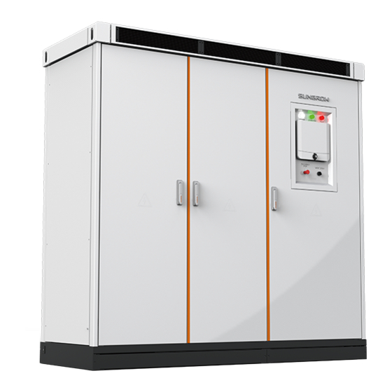
4 Product Description 4.1 Exterior Description Mechanical dimensions Width (W) Depth (D) Height Fig. 4-1 Mechanical dimensions of the inverter Width (W) Height (H) Depth (D) 2,150mm 2,120mm 850mm Weight The inverter weights about 1,900kg. 4.1.2 Inverter Appearance The face and main external components of the inverter are shown in the figure below. Fig. -
Page 18: Ventilation Design
4 Product Description Installation Manual Item Name Description Includes power indicator "POWER", operation indicator LED indicator "OPERATION", and fault indicator "FAULT" LCD touchscreen Displays the data and executes control commands Can be used to disconnect the AC side power supply Emergency stop button immediately in case of emergency Start/Stop switch... -
Page 19: Cable Entry Design
Installation Manual 4 Product Description Figure Description Air volume Right view Heat exchangers designed on the right side of the inverter for heat exchange, shown by D. 4.1.4 Cable Entry Design Bottom cable entry For standard inverter, all cables come into or go out of the inverter from the bottom. Cable entry positions and dimensions are shown in the figure below (in mm). -
Page 20: Main Circuit Diagram
4 Product Description Installation Manual 4.2 Main Circuit Diagram PV array converts the solar energy into DC energy and then sends it to the inverter DC input side after upstream combining. The DC energy is converted to AC energy through the inverter. -
Page 21: Installation Design
5 Installation Design 5.1 Selecting Installation Location 5.1.1 Basic Requirements With the degree of protection IP65, the inverter can be installed outdoors, but cannot be stored in a place with high humidity for long time. Considering noise generated during running, It is recommended to install the inverter in places far away from residential areas. -
Page 22: Foundation Requirements
5 Installation Design Installation Manual comply with 4S2 classification criterion. 5.2.3 Foundation requirements The inverter should be installed on a flat concrete foundation whose surface is made of fire-resistant materials, and the foundation must meet the following requirements: The degree of unevenness is <0.25% without any sinking. ... -
Page 23: Clearance Requirement
Installation Manual 5 Installation Design 5.2.4 Clearance Requirement During installation, reserve enough clearances around the inverter for maintenance, escape route, ventilation, and the like. The clearances described in this section are the minimum values. It is recommended to reserve larger space if possible, to ensure reliable and efficient running. Fig. -
Page 24: Cable Trench Design
5 Installation Design Installation Manual 5.2.5 Cable Trench Design Cable entries are located on the bottom of the inverter. For ease of installation and maintenance, it is recommended to route the cables connecting the inverter and external devices in the cable trench. Generally, cable trenches are dimensioned, designed and constructed by construction party with device weight and dimensions considered. -
Page 25: Others
Installation Manual 5 Installation Design Ventilation ducts of the inverter are shown in the following figure. Fig. 5-2 Ventilation ducts of the inverter 5.2.7 Others With the ingress of protection IP65, the inverter can be installed outdoors. According to EMC requirements and noise level, the inverter should be installed in industrial environment or outdoors. -
Page 26: Cable Fastening And Protection
5 Installation Design Installation Manual Parallel cable length (m) Min. distance (m) The data cables should be routed as close to the ground surface or supports as possible, such as support beam, steel channel or metal rail. 5.4 Cable Fastening and Protection 5.4.1 Cable Fastening To avoid overheating or even fires caused by poor contact or increased contact resistance due to cable lug loosening from stress, observe the following torque requirements when... -
Page 27: Mechanical Installation
6.1.1 Precautions The inverter should be transported and installed as an integrated unit. Never disassemble it without the permission of Sungrow. Transport the inverter in strict accordance with the descriptions in this chapter. Always keep in mind the non-central center of gravity of the inverter and gravity mark on the inverter package. -
Page 28: Transport
6 Mechanical Installation Installation Manual 6.1.2 Transport It is recommended to lay the DC input cables and AC output cables before moving the inverter to the installation location. The inverter can be transported without package nearby its installation site. The unpacked inverter can be transported by means of forklift, crane, slide rail, or the like. -
Page 29: Installation
Installation Manual 6 Mechanical Installation < 90 ° Fig. 6-1 Crane transport No matter which transportation tool is used, make sure: Keep the center of gravity in mind at all time. Keep the heavy weight of inverter in mind at all time. ... - Page 30 6 Mechanical Installation Installation Manual Fig. 6-2 Inverter fastening The sequence of connecting the inverter bottom to channel steels is shown in the figure below. Back Front Inverter Bolt Channel steels Cable trench Item Name Spring washer Flat washer Bottom of the inverter Channel steel Bolt Reassemble the front and back cover plates, as shown in the figure below.
-
Page 31: Electrical Connection
7 Electrical Connection 7.1 Safety Instructions For personal and device safety during electrical connection, observe the safety instructions described in this manual, especially in this chapter, and respect the national/local standards and regulations. 7.1.1 General Safety Rules High voltage! Electrical shock! ... -
Page 32: Installation Tools And Spare Parts
7 Electrical Connection Installation Manual 7.2 Installation Tools and Spare Parts Prepare the following tools and spare parts before installation: Torque wrench Screwdriver Wire stripper Terminal crimper Alcohol blast burner (or hot air blower) Allen wrench for terminal fixing ... -
Page 33: Check Connection Cable
Installation Manual 7 Electrical Connection All external cables are connected to the connection terminal through the cable entries on the bottom of the inverter. The protective grid is located at the lower part of the inverter cabinet. Open the door and find the protective grid of the connection area. Step 1 Loosen the screws at the edge of the protective grid to remove the grid. -
Page 34: Overview Of The Connection Area
7 Electrical Connection Installation Manual Fireproof Scheme A Scheme B Scheme C Seal the gaps with waterproof and fireproof materials after the cable connection. Otherwise, the electrical components inside the inverter unit cannot operate normally. 7.6 Overview of the Connection Area All cable connection terminals are at the lower part of the inverter with specific markings. -
Page 35: Dc Side Cable Connection
Installation Manual 7 Electrical Connection All the cables must have sufficient ampacity. The ampacity of the conductor is related to environmental conditions, conductor insulation materials, laying, wire materials, cross-sectional areas, and the like. The cross-sectional area of each cable must be selected according to the maximum DC current of the inverter with margin reserved. -
Page 36: Cable Connection Area
7 Electrical Connection Installation Manual The open-circuit voltage of the PV array cannot exceed the maximum DC input voltage. Otherwise, the inverter may be damaged. When finding a grounding fault of the PV module, remove the fault before performing DC cable connection. -
Page 37: Dc Side Cable Connection
Installation Manual 7 Electrical Connection Connect cables strictly according to the wiring marks on the device. Open/Close the DC switches strictly according to the internal identifications. 7.8.3 DC Side Cable Connection Proceed as follows to connect the DC side cables. Ensure that output circuit breakers of all upstream combiner boxes of the inverter have Step 1 been disconnected. -
Page 38: Ac Side Cable Connection
7 Electrical Connection Installation Manual Incorrect cable connection sequence may cause fires. Connect the parts in correct order. Ensure connection firmness. Poor connection or oxidation of the contact surface may cause overheating and fires. The selected bolts should be of appropriate length, a little bit longer than the depth of installation hole. -
Page 39: Cable Connection
Installation Manual 7 Electrical Connection includes three cables of each phase. The distance between groups should be at least twice of the cable cross-sectional area. Schematic diagram is shown below: Fig. 7-3 AC cable routing Item Description Requirement Cable cross-section B≥2A Distance between cable groups 7.9.3 Cable Connection... - Page 40 7 Electrical Connection Installation Manual lug. Insert the cable lug into the heat-shrinkable tubing to completely cover the crimping hole on the cable lug. Shrink the tubing with a hot air blower. Cable protectors are recommended at the cable crosses if multi-core cables are used.
-
Page 41: Grounding Connection
Installation Manual 7 Electrical Connection Copper Flat Cu-Al transition lug Bolt Spring washer bus bar washer Incorrect cable connection sequence may cause fires. Connect the parts in correct order. Ensure connection firmness. Poor connection or oxidation of the contact surface may cause overheating and fires. -
Page 42: Description Of Grounding Terminal
7 Electrical Connection Installation Manual During grounding, note that: All grounding connections must comply with national/local standards and regulations. Grounding connection between the device and the grounding electrode must be reliably secured. Measure the grounding resistance after grounding connection to ensure the resistance is no more than 4 Ω. - Page 43 Installation Manual 7 Electrical Connection Fig. 7-7 Location of RS485 terminals Single-inverter communication Figure below shows the communication for a single inverter. Connect the communication port A1 and B1 to RS485/RS232 converter and then to the monitoring PC. RS485-232 converter :A1 Bottom:B1 5 4 3 2 1...
- Page 44 +serial port cable RS232 Serial port cable RS232 USB cable Internet cable Fig. 7-9 RS485 communication for multiple inverters Logger is an optional device. Users can order it from Sungrow. For more information Logger, download related documentations www.sungrowpower.com. When there is more than one inverter in the PV plant, each monitoring system of the inverter should be equipped with a Logger.
-
Page 45: Ethernet Communication Solution
LAN. Electricity-optics change device and the optical cables should be designed in accordance with the reality or adopt the available LAN system. Sungrow can provide professional solutions. RS485 cable should be shielded twisted-pair for communication quality (RVVP-2*1.0 shielded twisted-pair cable is recommended). -
Page 46: Supply Modes
7 Electrical Connection Installation Manual Inverter Inverter Inverter Ethernet switch Fig. 7-12 Ethernet communication for multiple inverters Running data and other information on the inverter are finally uploaded to the Insight/iSolarCloud server via the Logger. Users can monitor the inverter locally via the Insight monitoring system or monitor the inverter remotely via the iSolarCloud. -
Page 47: Internal Power Supply
Installation Manual 7 Electrical Connection Circuit breaker Function Control the internal power supply mode Control the external power supply mode Distinguish between the circuit breakers for controlling the internal and external power supply modes according to device markings. The user can select the desired power supply mode according to the following settings. 7.12.2 Internal Power Supply The internal power supply mode has been set before delivery, and it can be used directly without any setting. -
Page 48: Installation Checklist
The cable entries of the inverter are equipped with aluminum cover plate. Please do not use cover plate of other materials to seal the cable entries. For details, consult Sungrow. 7.14 Installation Checklist After installation, perform a thorough check. -
Page 49: Commissioning
8 Commissioning 8.1 Commissioning Requirements Before commissioning, all installations should be checked thoroughly again. Ensure all the cable connections are secure and all bolts are fixed properly. Ensure DC side voltage meets inverter requirements and the polarity is correct. ... -
Page 50: Pv Array Check
8 Commissioning Installation Manual Check and ensure inverter and switches upstream and downstream meet the requirements and flexible enough. 8.2.3 PV Array Check Ensure the measuring devices are connected and used correctly. Otherwise, there will be electric arc. The DC side voltage cannot exceed the maximum DC voltage of the inverter. Excessively high DC voltage can damage the inverter or even cause safety accidents. -
Page 51: Preparation For Starting
Installation Manual 8 Commissioning 8.3 Preparation for Starting When all the foregoing items are inspected and comply with the requirements, prepare to start the device. Place the disassembled protection grills to their original positions and ensure the connection is secure. ... -
Page 52: Commissioning Completion
8 Commissioning Installation Manual 8.6 Commissioning Completion After the inverter is successfully connected to the grid, the following tests need to be performed: If all the start-up procedures have been performed, check the operating condition of the inverter. Check whether there are anomalies: abnormal noise, overheating, smoking or unusual smell. -
Page 53: Appendix
9 Appendix 9.1 Technical Parameters 9.1.1 Electrical Parameters Input parameters (DC side) Parameter SG1250UD SG1500UD Max. DC voltage 1,100Vdc 1,100Vdc Start-up voltage 540V 600V MPP voltage range 520V~1000V 580V~1000V Min. operating voltage 520V 580V Max. input current 2,712A 2,896A Output parameters (AC side) - Page 54 Unforeseen calamity or force majeure The use of supplied software produced by Sungrow Power Supply Co., Ltd. is subject to the following conditions: Sungrow Power Supply Co., Ltd. assumes no liability for direct or indirect damages arising from the use of software.
- Page 55 Installation Manual 9 Appendix China (HQ) Australia Sungrow Power Supply Co., Ltd Sungrow Australia Group Pty. Ltd. Hefei Sydney +86 551 65327834 +61 2 9922 1522 service@sungrowpower.com service@sungrowpower.com.au Brazil France Sungrow France – Siege Social SungrowDo Brasil Sao Paulo Paris +55 11 2366 1957 latam.service@sa.sungrowpower.com...
- Page 56 9 Appendix Installation Manual Romania Turkey Service Partner - Elerex Sungrow Deutschland GmbH Turkey Istanbul Representative Bureau +40 241762250 Istanbul service.romania@sungrow.co +90 2127318883 service.turkey@sungrow.co U.S.A, Mexico Sungrow Power UK Ltd. Sungrow USA Corporation Milton Keynes PhoenixArizona +44 (0) 0908 414127 +1833 7476937 service.uk@sungrow.co...
Need help?
Do you have a question about the SG1250UD and is the answer not in the manual?
Questions and answers