Falcon F900 SERIES User, Installation And Servicing Instructions
Gas ovens
Hide thumbs
Also See for F900 SERIES:
- User, installation and servicing instructions (58 pages) ,
- User, installation and servicing instructions (26 pages) ,
- User, installation and servicing instructions (42 pages)
Table of Contents
Advertisement
Quick Links
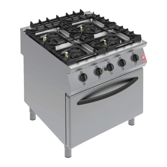
OPEN TOP & RANGES
DATE PURCHASED:
MODEL NUMBER:
SERIAL NUMBER:
DEALER:
SERVICE PROVIDER:
T100874
Published: 02/10/2015
F900 SERIES
User, installation and servicing instructions
G9042, G9042A,
G9084, G9084A, G9084B,
G90126, G90126A, G90126B,
G9184, G9184A, G9184B
Read these instructions before use
REV.4
1
Advertisement
Table of Contents


Need help?
Do you have a question about the F900 SERIES and is the answer not in the manual?
Questions and answers