Table of Contents
Advertisement
Quick Links
Advertisement
Table of Contents

Subscribe to Our Youtube Channel
Related Manuals for Falcon G9440


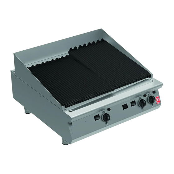
Summary of Contents for Falcon G9440
- Page 1 F900 SERIES User, installation and servicing instructions GAS CHARGRILL G9440, G9460, G9490, G94120 Read these instructions before use DATE PURCHASED: MODEL NUMBER: SERIAL NUMBER: DEALER: SERVICE PROVIDER: REV. 4 T100873 Published: 23/08/2016...
- Page 2 Dear Customer, Thank you for choosing Falcon Foodservice Equipment. This manual can be downloaded from www.falconfoodservice.com or scan here. IMPORTANT: Please keep this manual for future reference. Falcon Foodservice Equipment HEAD OFFICE Wallace View, Hillfoots Road, Stirling. FK9 5PY. Scotland.
- Page 3 SYMBOLS • • SCREWDRIVER • COOKING OIL • GREASE SPANNER • • FLAME • WARNING • VIEWPORT SPARK IGNITION • •IGNITER ALLEN KEY...
- Page 4 These instructions are only valid if the country code appears on the appliance. If the code does not appear on the appliance, refer to the technical instructions for adapting the appliance to the conditions for use in that country. Installation must meet national or local regulations. Attention must be paid to: gas safety (installation &...
-
Page 5: Table Of Contents
CONTENTS APPLIANCE INFORMATION ..................6 OPERATION ......................7 COMPONENT PARTS .................... 7 CONTROLS ......................7 USING THE APPLIANCE ..................8 CLEANING AND MAINTENANCE ................9 SPECIFICATION ...................... 10 DIMENSIONS / CONNECTION LOCATIONS ............12 INSTALLATION ......................13 SITING / CLEARANCES ..................13 VENTILATION ....................... -
Page 6: Appliance Information
1.0 APPLIANCE INFORMATION This appliance has been CE-marked on the basis of compliance with the relevant EU directives for the heat inputs, gas pressures and voltages stated on the data plate. A - Serial No B - Model No C - Flue Type D - Gas Category E - Gas Pressure F - Gas Type... -
Page 7: Operation
D – Burner Baffle E – Splashguard F – Burner G – Control Knob H – Spark Igniter I – Drip Tray J* – Deflector K – Fat Jug * Not required in G9440. CONTROLS A – Spark Igniter B – Zone Indicator... -
Page 8: Using The Appliance
USING THE APPLIANCE 2.3.1 Before use, clean the appliance inside and out. See section 3. 2.3.2 Position burner baffles and brander bars correctly. A - High position B – Low position C – Burner Baffle D – Baffle support E– Lightly oil bars 2.3.3 Fill about a 1/3 of the drip tray with water. -
Page 9: Cleaning And Maintenance
THE DRIP TRAY DEFLECTORS MUST ALWAYS BE IN PLACE WHEN THE CHARGRILL IS IN OPERATION. IF A BURNER TURNS OFF, WAIT 3 MINUTES BEFORE RE- LIGHTING. 2.3.5 Ensure water in drip tray does not dry up by topping up periodically. 2.3.6 TURNING THE BURNER OFF Turn knob to ‘Off’... -
Page 10: Specification
4.0 SPECIFICATION INJECTOR SIZES Gas Type G9440 Ø2.5 Amal 310 Amal 310 G9460 Ø2.5 Amal 310 Amal 310 G9490 Ø2.5 Amal 300 Amal 300 G94120 Ø2.5 Amal 310 Amal 310 Pilot Injectors 31.2 Supply mbar 29/50 Pressure Operating mbar Pressure... -
Page 12: Dimensions / Connection Locations
5.0 DIMENSIONS / CONNECTION LOCATIONS A – GAS INLET... -
Page 13: Installation
This appliance must be installed with sufficient ventilation to prevent the occurrence of unacceptable concentrations of substances harmful to health in the room in which they are installed. Installer must consult any additional local / national regulations. COMBUSTION AIR REQUIREMENTS G9440 G9460 G9490 G94120 7.5m... -
Page 14: Gas Supply & Connection
GAS SUPPLY & CONNECTION 6.3.1 Installation pipe work should be fitted in accordance with local / national standards. The pipe work must not be smaller than unit gas inlet connection, i.e. Rp¾ (¾” B.S.P.). If using flexible hosing, the hose must be sized to conform with the hose manufacturers specifications and the length must not exceed 1.5m. -
Page 15: Assembly
ASSEMBLY 6.4.1 Position appliance and level using feet adjusters as shown below. 6.4.2 Connect appliance to gas supply and test for gas tightness (see 6.3) COMMISSIONING 6.5.1 Remove brander bars and burner baffles. 6.5.2 Ensure burner pressure is correct (see 4.0 for operating pressures. See 8.6 for governor adjustment) 6.5.3 Light all pilots and ensure all stay lit. -
Page 16: Suiting
This can be supplied by Falcon part no – 523400021 6.6.5 Run a bead of silicon 5mm from profile edge as highlighted below. - Page 17 6.6.6 Slide suited units into position 6.6.7 Right hand unit: Screw the M5 x 40 screw (supplied in the kit) into one of the suiting plates as shown and then insert through the front fixing holes of both units. 6.6.8 (B) Left hand unit: Slide the penny and lock washer on to the screw and secure using the M5 nut.
-
Page 18: Conversion
7 CONVERSION BEFORE INSPECTION, SERVICING OR CONVERSION, TURN OFF GAS AT ISOLATOR AND REMOVE BRANDER BARS AND BURNER BAFFLES. GAS CONVERSION CHECK LIST Change injectors in burner(s) and pilots(s) (see 8.2 & 8.4). Adjust by-pass screw for LP by turning screw fully clockwise. To convert back to Ng, ensure screw is turned fully clockwise and then turn screw two complete turns anti- clockwise. -
Page 19: Servicing
8 SERVICING BURNERS 8.1.1 Remove burners as shown. 8.1.2 Clean burners (see section 3). 8.1.3 Clean ports. - Page 20 8.1.4 For conversion, adjust aeration shroud as shown.
-
Page 21: Injectors
8.1.5 When replacing burner, ensure locating lugs locate in the rear support bar correctly. INJECTORS 8.2.1 Remove injector as shown. 8.2.2 Clean injector. 8.2.3 Check washers are clean and serviceable. 8.2.4 After replacement, check burner performance. -
Page 22: Control Panel
CONTROL PANEL 8.3.1 Remove as shown. PILOT ASSEMBLY 8.4.1 Remove pilot components as shown. A – Thermocouple B – Pilot gas pipe C – Spark electrode D – Pilot bracket... -
Page 23: Gas Valve
GAS VALVE 8.5.1 Remove gas valve as shown. A – Thermocouple B – Pilot gas pipe C – Main gas pipe D – Valve clamp E – Bypass screw 8.5.2 Service valve as shown. -
Page 24: Governor
GOVERNOR 8.6.1 This applies to G20 and G30 (50mb) models only. 1 – Gas in 2 – Gas out 3 – Direction of flow GOVERNOR SUPPLIED IS MAINTENANCE FREE. ENSURE THE BLUE DUST CAP COVERING THE VENT IS FITTED AND IN GOOD CONDITION. -
Page 25: Fault Finding
9 FAULT FINDING FAULT POSSIBLE CAUSES REMEDY Pilot does not light. No gas supply. Restore supply. Faulty spark igniter. Test igniter button, lead and electrode. Replace as necessary. Pilot does not stay lit. Faulty thermocouple. Check thermocouple is tight and tip is in pilot flame. Main burner(s) does not light. -
Page 26: Spare Parts
10 SPARE PARTS Main spare parts: Gas valve Pilot assembly Thermocouple Fat jug Drip tray Drip tray deflector Control knob Spark igniter When ordering spares, quote the following: Model Number Serial number Gas Type This information is found on data plate on front panel.
Need help?
Do you have a question about the G9440 and is the answer not in the manual?
Questions and answers