Sign In
Upload
Download
Table of Contents
Contents
Add to my manuals
Delete from my manuals
Share
URL of this page:
HTML Link:
Bookmark this page
Add
Manual will be automatically added to "My Manuals"
Print this page
×
Bookmark added
×
Added to my manuals
Manuals
Brands
Falcon Manuals
Ranges
G9081
User, installation and servicing instructions
Falcon G9081 User, Installation And Servicing Instructions
Solid top & ranges
Hide thumbs
1
2
3
4
Table Of Contents
5
6
7
8
9
10
11
12
13
14
15
16
17
18
19
20
21
22
23
24
25
26
27
28
29
30
31
32
page
of
32
Go
/
32
Contents
Table of Contents
Bookmarks
Table of Contents
Table of Contents
1 Appliance Information
2 Operation
Component Parts
Controls
Using the Appliance
Turning the Burners off
3 Cleaning and Maintenance
Hob
Oven
Flue Capper
4 Specification
TABLE B – Heat Inputs
5 Dimensions / Connection Locations
6 Installation
Siting / Clearances
Ventilation
Gas Supply & Connection
Assembly
Commissioning - Hob
Commissioning - Oven
Suiting
7 Conversion
Gas Conversion Check List
8 Servicing
Control Panel
Injector (Hob)
Pilot (Hob)
Removal of Door
Injector (Oven)
Pilot (Oven)
Aeration (Hob)
Gas Valve (Hob)
Gas Valve (Oven)
Pressure Adjustment
Governor
9 Fault Finding
10 Spare Parts
11 Servicing Information
Advertisement
Quick Links
1
Spare Parts
Download this manual
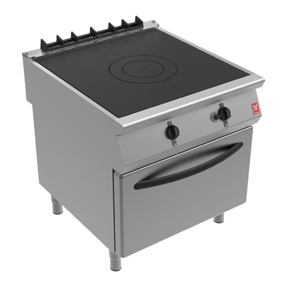
F900 SERIES
User, installation and servicing instructions
SOLID TOP & RANGES
G9081/G9181
Read these instructions before use
DATE PURCHASED:
MODEL NUMBER:
SERIAL NUMBER:
DEALER:
SERVICE PROVIDER:
T100892
Rev 9
Published: 08/09/2016
1
Table of
Contents
Previous
Page
Next
Page
1
2
3
4
5
Advertisement
Table of Contents
Need help?
Do you have a question about the G9081 and is the answer not in the manual?
Ask a question
Questions and answers
Related Manuals for Falcon G9081
Cash Counter Falcon F900 Series User, Installation And Servicing Instructions
Induction solidtop counter (58 pages)
Fryer Falcon F900 Series User, Installation And Servicing Instructions
(53 pages)
Fryer Falcon F900 Series User, Installation And Servicing Instructions
Electric twin well fryer (45 pages)
Fryer Falcon F900 SERIES User, Installation And Servicing Instructions
Electric single well fryer (44 pages)
Fryer Falcon F900 SERIES User, Installation And Servicing Instructions
(38 pages)
Grill Falcon E9460 User, Installation And Servicing Instructions
Electric chargrill (37 pages)
Cookers Falcon F900 Series User, Installation And Servicing Instructions
Induction counter tops (34 pages)
Pasta Maker Falcon E9241 User, Installation And Servicing Instructions
Pasta cooker (31 pages)
Cooktop Falcon i9042 User, Installation And Servicing Instructions
Induction counter tops (31 pages)
Oven falcon F900 SERIES User, Installation And Servicing Instructions
Gas ovens (31 pages)
Pasta Maker Falcon E9241 User, Installation And Servicing Instructions
Pasta cooker (25 pages)
Griddle Falcon F900 SERIES User, Installation And Servicing Instructions
Gas griddle (25 pages)
Commercial Food Equipment Falcon F900 Series User, Installation And Servicing Instructions
Bratt pan (21 pages)
Kitchen Appliances Falcon F900 Series User, Installation And Servicing Instructions
Boiling pan (16 pages)
Commercial Food Equipment Falcon F900 Series User, Installation And Servicing Instructions
Neutral unit (14 pages)
Grill Falcon E600 User, Installation And Servicing Instructions
Rise and fall grill (12 pages)
This manual is also suitable for:
F900 series
G9181
G9042a
G9042
G9084
G90126
...
Show all
G9084a
G9084b
G90126a
G90126b
G9184
G9184a
G9184b
Table of Contents
Print
Rename the bookmark
Delete bookmark?
Delete from my manuals?
Login
Sign In
OR
Sign in with Facebook
Sign in with Google
Upload manual
Upload from disk
Upload from URL


Need help?
Do you have a question about the G9081 and is the answer not in the manual?
Questions and answers