Table of Contents

Subscribe to Our Youtube Channel
Related Manuals for Falcon E9460


Summary of Contents for Falcon E9460
- Page 1 F900 SERIES User, installation and servicing instructions ELECTRIC CHARGRILL E9460/E9490 Read these instructions before use DATE PURCHASED: MODEL NUMBER: SERIAL NUMBER: DEALER: SERVICE PROVIDER: T100896 Rev No 3 Published: 23/05/2019...
- Page 2 Dear Customer Thank you for choosing Falcon Foodservice Equipment. This manual can be downloaded from www.falconfoodservice.com or scan here: IMPORTANT: Please keep this manual for future reference. Falcon Foodservice Equipment HEAD OFFICE Wallace View, Hillfoots Road, Stirling. FK9 5PY. Scotland.
- Page 3 SYMBOLS SCREWDRIVER SPANNER COOKING OIL GREASE WARNING SPARK IGNITION FLAME VIEWPORT ALLEN KEY IGNITER C SPANNER REMOVE DEVICE PLUG REMOVER...
- Page 4 Ensure the supply cord is routed free from the appliance to avoid damage. The appliance has been designed and approved to use Falcon kick plates; non Falcon kick plates could potentially adversely affect the performance of the appliance by restricting the air to the appliance.
- Page 5 Training and competence To help ensure the safe use of this appliance there is a requirement for you to provide whatever information, instruction, training and supervision as is necessary to ensure, so far as is reasonably practicable, the health and safety of all users. For further help and information on training and competence we would refer you the Health and Safety Executive website;...
-
Page 6: Table Of Contents
CONTENTS APPLIANCE INFORMATION ..................7 OPERATION ......................8 COMPONENT PARTS .................... 8 CONTROLS ......................10 USING THE APPLIANCE ..................11 CHEF’S RECOMMENDATIONS ................11 CLEANING AND MAINTENANCE ................12 CLEANING AND MAINTENANCE ................ 13 PTFE FITTING ...................... 15 SPECIFICATION ...................... 16 APPLIANCE WEIGHT TABLE ................ -
Page 7: Appliance Information
1.0 APPLIANCE INFORMATION This appliance has been CE-marked on the basis of compliance with the relevant EU directives for the heat inputs, gas pressures and voltages stated on the data plate. A - Serial No B - Model No C - Flue Type D - Gas Category E - Gas Pressure F - Gas Type... -
Page 8: Operation
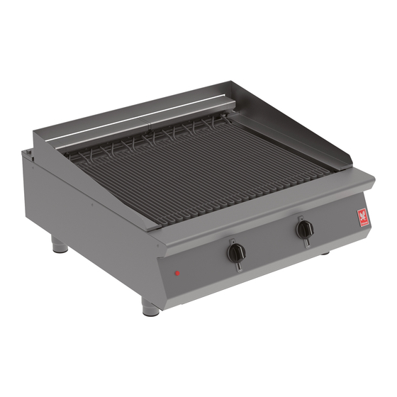
2.0 OPERATION 2.1 COMPONENT PARTS E9460 Element Drip Tray Power neon (Red) Drip Tray Insert Element supports PTFE Front Clamp Left hand splashguard PTFE Front Liner Right hand splashguard PTFE Rear Clamp Rear splashguard infill PTFE Rear Liner Drain Cleaning tool... - Page 9 E9490 LH Element Drip tray RH Element Drip Tray Insert Power neon (Red) PTFE Front Clamp Element supports PTFE Front Liner Left hand splashguard PTFE Rear Clamp Right hand splashguard PTFE Rear Liner Rear splashguard infill Cleaning tool Drain...
-
Page 10: Controls
2.2 CONTROLS E9460 E9490 Power neon (Red) Power neon (Red) Control Left hand control Cleaning setting Right hand control Cleaning setting... -
Page 11: Using The Appliance
USING THE APPLIANCE 2.3.1 Before use, clean the appliance inside and out. See section 3. 2.3.2 Ensure the drip tray is fitted. 2.3.3 Power Neon (red) will light when there is mains power to the appliance 2.3.4 The appliance is fitted with a numbered control knob which indicates regulator setting. THE CLEAN SETTING IS USED FOR CLEANING ONLY, IN THIS POSITION THE ELEMENTS CAN REACH 400°C. -
Page 12: Cleaning And Maintenance
3.0 CLEANING AND MAINTENANCE When removing heavy items to aid cleaning or maintenance particular care should be taken. A manual handling risk assessment is the best way to determine the level of risk to anyone using or maintaining this equipment. To help with such an evaluation we have included the weights of individual components that may present significant risk. -
Page 13: Cleaning And Maintenance
3.1 CLEANING AND MAINTENANCE 3.1.1 Turn the control knob to the cleaning setting. 3.1.2 Allow to run at maximum temperature for approximately 15 minutes. 3.1.3 At this setting most food debris should carbonize and fall off the elements. 3.1.4 Scrape off any remaining debris using the element cleaning tool provided. 3.1.5 When cold the elements may also be cleaned using a cloth and hot soapy water. - Page 14 3.1.7 Clean the pan with warm water and detergent. 3.1.8 To clean the drip tray remove it from the appliance and warm water and detergent. 3.1.9 The splash guard is removable for cleaning. 3.1.10 The front and rear element support bars are also removable for cleaning. DO NOT USE COARSE ABRASIVES TO CLEAN EXTERIOR PANELS.
-
Page 15: Ptfe Fitting
3.1.12 If the unit is fitted with PTFE liners, ensure any debris that has collected behind the liners is removed on a daily basis. THE PTFE SHEET SHOULD NOT BE ALLOWED TO COME INTO CONTACT WITH THE ELEMENTS WHEN HOT. 3.1.13 The PTFE sheeting should be cleaned using non-corrosive agents. -
Page 16: Specification
3.2.4 Re-fit PTFE Clamps, element support bars and splashguards as required. 4.0 SPECIFICATION 4.1 APPLIANCE WEIGHT TABLE APPLIANCE UNIT WEIGHT (kg) PACKED WEIGHT (kg) E9460 E9490 4.2 TECHNICAL DATA TABLE E9460 CURRENT POWER MIN (A) @ MAX (A) @ ACTUAL (A) @... -
Page 17: Dimensions / Connection Locations
20.00 23.33 22.22 3.36 IF ANY CURRENT IS OUT WITH THESE TOLERANCES, THE CAUSE MUST BE INVESTIGATED AND RECTIFIED. 5.0 DIMENSIONS / CONNECTION LOCATIONS... -
Page 18: Installation
6.0 INSTALLATION ELECTRICAL SAFETY AND ADVICE REGARDING SUPPLEMENTARY ELECTRICAL PROTECTION... -
Page 19: Siting / Clearances
Commercial kitchens and foodservice areas are environments where electrical appliances may be located close to liquids, or operate in and around damp conditions or where restricted movement for installation and service is evident. The installation and periodic inspection of the appliance should only be undertaken by a qualified, skilled and competent electrician;... -
Page 20: Assembly
6.2 ASSEMBLY 6.2.1 Position the appliance and level using feet adjusters as shown below. TAKE CARE WHEN MOVING AN APPLIANCE FITTED WITH CASTORS. 6.3 ELECTRIC SUPPLY & CONNECTION The location of the electrical inlet is as seen in section 5.0. This unit is suitable for AC supplies only. -
Page 21: Commissioning
THIS APPLIANCE MUST BE EARTHED 6.4 COMMISSIONING Refer to section 2.0 for operation. Carry out the following operation: 6.4.1 Turn on mains power supply on. 6.4.2 Ensure red neon illuminates. 6.4.3 Turn control knob to the clean setting. 6.4.4 Let the appliance heat up. At this setting the chargrill is constantly on and can reach temperatures up to 400 6.4.5 Switch appliance off. -
Page 22: Suiting
The DLS system Patent no. GB 2540131 is designed to give a quick and easy suiting solution. If you require an improved seal between appliances we recommend you use, a food grade, high temperature silicon sealant. This can be supplied by Falcon part no – 523400021 6.5.1 Before levelling and suiting units ensure the units are fully built, including all... - Page 23 6.5.5 Run a bead of silicon 5mm from profile edge as highlighted below. 6.5.6 Slide suited units into position 6.5.7 (A) Right hand unit: Screw the M5 x 40 screw (supplied in the kit) into one of the suiting plates as shown and then insert through the front fixing holes of both units. 6.5.8 (B) Left hand unit: Slide the penny and lock washer on to the screw and secure using the M5 nut.
- Page 24 6.5.10 (D) Replace fixings on the rear hob and tighten screw caps into position. 6.5.11 Replace control panel.
-
Page 25: Servicing
7.0 SERVICING BEFORE ATTEMPTING ANY MAINTENANCE, ISOLATE THE APPLIANCE AT THE MAINS SWITCH AND TAKE STEPS TO ENSURE THAT IT IS NOT INADVERTENTLY SWITCHED ON. THERE ARE NO SERVICEABLE COMPONENTS LOCATED IN THE ELEMENT HEAD. THE MICRO SWITCH IS LOCATED IN THE PIVOT HOUSING OF THE ELEMENT ASSEMBLY AS SHOWN IN STEP 7.5. -
Page 26: Access Panel Removal
7.1 ACCESS PANEL REMOVAL 7.1.1 Remove access panel as shown below. 7.2 CONTROL PANEL REMOVAL 7.2.1 Remove control panel as shown below. -
Page 27: Energy Regulator, Switch And Neon Removal
7.3 ENERGY REGULATOR, SWITCH AND NEON REMOVAL 7.3.1 Remove control panel as shown in section 7.2.1 7.3.2 Remove energy regulator and switch as shown below. 7.3.3 Remove neon as shown below. -
Page 28: Contactor Removal
7.4 CONTACTOR REMOVAL 7.4.1 Remove control panel as shown in section 7.2.1 7.4.2 Remove contactor as shown below. 7.5 MICRO SWITCH REMOVAL 7.5.1 Remove splashguards and rear panel as show below... -
Page 29: Heating Elements Removal
7.5.2 Remove two hex screws from each side of underside of the hob. Pull back pin and remove element head end covers from the topside of hob and repeat on opposite side if required. 7.5.3 Disconnect the wires from micro switch and unfasten two cap screws to remove micro switch. - Page 30 7.6.5 Feed cables from front of unit and out at rear cable entry hole to enable element assembly lift off as shown below.
-
Page 31: Circuit Diagrams
7.7 CIRCUIT DIAGRAMS 7.7.1 E9490 Circuit Diagram... - Page 32 7.7.2 E9460 Circuit Diagram...
-
Page 33: Wiring Diagrams
7.8 WIRING DIAGRAMS 7.8.1 E9490 Wiring Diagram... - Page 34 7.8.2 E9460 Wiring Diagram...
-
Page 35: Accessories
8.0 ACCESSORIES 9.0 FAULT FINDING FAULT POSSIBLE CAUSES REMEDY USER *ENG Check mains power is Unit will not turn ON No power to unit connected and turned on Heating elements will not Element not fully Ensure element is fully ... -
Page 36: Spare Parts
Micro switch 735960015 Cleaning tool scraper 733650009 737630011 Energy regulator E9460 Control panel 733650000 733650004 E9460 PTFE front & rear liner set E9460 Element 735950000 E9460 Drip Tray 533550002 E9490 Control panel 733660000 E9490 PTFE front & rear liner set 733660002... -
Page 37: Service Information
11.0 SERVICE INFORMATION It is recommended to have a maintenance contract with a local service provider. SERVICELINE CONTACT: (UK only) Phone: +441438 363 000 Warranty Policy Shortlist For our warranty policy please go to www.falconfoodservice.com...
Need help?
Do you have a question about the E9460 and is the answer not in the manual?
Questions and answers