Table of Contents
Advertisement
Quick Links
d e v e l o p i n g
s o l u t i o n s
Operating instructions
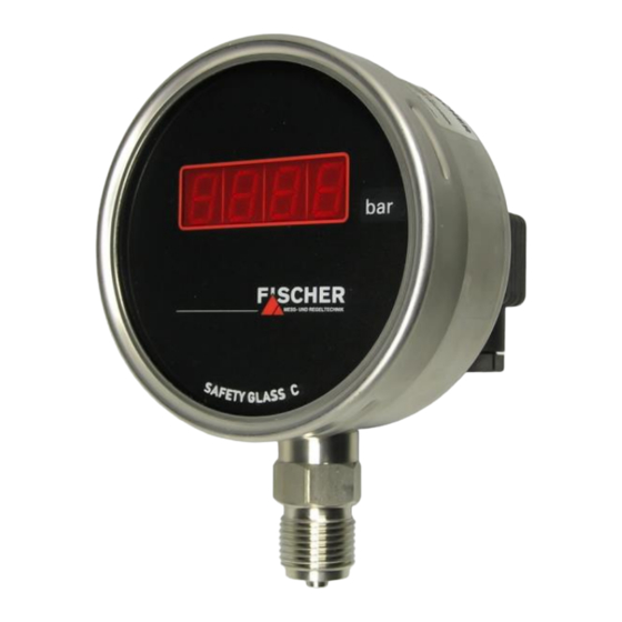
ME01
Digital manometer
Table of Contents
1
Safety guidelines
2
Application purpose
3
Product and function description
4
Installation and assembly
5
Commissioning
6
Maintenance
7
Transportation
8
Service
9
Accessories
10 Waste disposal
11 Technical Data
12 Dimensional drawings
13 Order Codes
14 Attachments
1
Safety guidelines
1.1
General Information
This operating manual contains instruc-
tions fundamental to the installation, op-
eration and maintenance of the device
that must be observed unconditionally. It
must be read by the assembler, operator and the
specialized personnel in charge of the instrument
before it is installed and put into operation. This op-
erating manual must always be accessible at the
place of installation.
The subsequent sections on general safety instruc-
tions 1.2 - 1.7 as well as the following special in-
structions ranging from intended use to disposal 2-
10 contain important safety instructions the non-
observance of which can cause danger to persons,
animal and physical objects.
1.2
Personnel Qualification
Staff assigned to assembly, operating, maintenance
and inspection tasks shall be adequately qualified
for this work and must be sufficiently instructed and
trained to meet the requirements of assembly, op-
erating, maintenance and inspection work.
1.3
Risks due to Non-Observance of Safe-
ty Instructions
Non-observance of these safety instructions, the in-
tended use of the device or the limit values given in
the technical specifications can be hazardous or
cause harm to persons, the environment or the
plant itself. Fischer Mess- und Regeltechnik GmbH
will not be liable for damage claims if this should
happen.
1.4
Safety Instructions for the Operating
Company and the Operator
The safety instructions governing correct operation
of the instrument must be observed. The operating
company must make them available to the installa-
tion, maintenance, inspection and operating per-
sonnel. Dangers arising from electrical components,
energy discharged by the medium, escaping medi-
um and incorrect installation of the instrument must
be eliminated. For more information, please see the
applicable national and international regulations,
such as DIN, EN, accident prevention regulations
(UVV) and - for industry-specific individual applica-
tions - also in the industry guidelines issued by the
DVWG, Ex, GL, etc. as well as VDE and local
EVUs.
Advertisement
Table of Contents

Subscribe to Our Youtube Channel
Related Manuals for FISCHER Me01 Series


Summary of Contents for FISCHER Me01 Series
- Page 1 Fischer Mess- und Regeltechnik GmbH before it is installed and put into operation. This op- will not be liable for damage claims if this should erating manual must always be accessible at the happen.
-
Page 2: Application Purpose
The high resistance of the ceramic ma- tions/alterations required will be carried out by terials that are used allow use even for aggressive Fischer Mess- und Regeltechnik GmbH only. media. Impermissible modes of operation There is a resistance measuring bridge attached to... -
Page 3: Maintenance
Electrical connections Maintenance • By authorized and qualified specialized person- The instrument is maintenance-free. nel only. We recommend checking the instrument at regular • The electrical connection of the device shall be intervals to ensure reliable operation and a long performed according to relevant VDE and local service life. -
Page 4: 11 Technical Data
11 Technical Data Measuring range in bar 0-1.6 0-2.5 0-10 0-16 0-25 0-40 0-60 Overpressure-proof in bar Measuring range in bar - 1..0 -1..0.6 -1..1.5 -1..3 -1..5 -1..9 -1..15 0...-1 Overpressure-proof in bar Linearity < 1 % of the measuring range Hysteresis <... -
Page 5: 12 Dimensional Drawings
12 Dimensional drawings (all dimensions in mm unless otherwise specified) M16 x 1.5 SW22 Manometer connection port G1/2 Acc. DIN EN 837 5 | 8 Page... -
Page 6: 13 Order Codes
13 Order Codes Digital manometer Type ME01 Measuring range 0 ... 1 bar ..........> 0 2 0 ...1.6 bar ..........> 0 3 0 ...2.5 bar ..........> 0 4 0 ... 4 bar ..........> 0 5 0 ... 6 bar ..........> 0 6 0 ... -
Page 7: Attachments
14 Attachments 7 | 8 Page... - Page 8 Technische Änderungen vorbehalten • Subject to change without notice • Changements techniques sous réserve Fischer Mess- und Regeltechnik GmbH • Bielefelder Str. 37a • D-32107 Bad Salzuflen • Tel. +49 5222 9740 • Fax +49 5222 7170 • eMail: info@fischermesstechnik.de • www.fischermesstechnik.de...
Need help?
Do you have a question about the Me01 Series and is the answer not in the manual?
Questions and answers