
Related Manuals for FISCHER PRO-LINE DE91


Summary of Contents for FISCHER PRO-LINE DE91
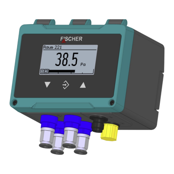
- Page 1 Modbus II 3G Ex ec IIC T4 Gc II 3D Ex tc IIIB T125°C Dc Operating manual DE91 Differential pressure transmitter PRO-LINE ® for low pressure measurements...
-
Page 2: Version History
Great care was taken when compiling the texts and illustrations; Nevertheless, errors cannot be ruled out. The company FISCHER Mess- und Regeltechnik GmbH will not accept any legal responsibility or liability for this. -
Page 3: Table Of Contents
FISCHER Mess- und Regeltechnik GmbH Table of contents Table of contents 1 Safety instructions......................7 1.1 General........................... 1.2 Personnel Qualification ......................1.3 Risks due to Non-Observance of Safety Instructions............. 1.4 Safety Instructions for the Operating Company and the Operator ......... - Page 4 Table of contents FISCHER Mess- und Regeltechnik GmbH 3.4.5 Devices with Modbus (and 4 switch outputs)................27 3.4.5.1 Connection to an existing Modbus RTU network............27 3.4.5.2 Auxiliary energy supply....................28 3.4.5.3 M12 connector 1: Modbus ................... 29 3.4.5.4 M12 connector 2: Switch outputs................. 29 3.4.6 Devices with IO-Link ........................
- Page 5 FISCHER Mess- und Regeltechnik GmbH Table of contents 5.4.1.2 Measurement C1 ......................58 5.4.1.2.1 Measuring range C1 unit ..................5.4.1.2.2 Measuring range C1 start..................5.4.1.2.3 Measuring range C1 end..................5.4.1.2.4 Damping C1 ......................5.4.1.2.5 Offset C1 ........................5.4.1.2.6 Zero-point window C1 ....................
- Page 6 Table of contents FISCHER Mess- und Regeltechnik GmbH 5.5 Info ............................105 5.6 Service ...........................106 5.6.1 Firmware update ........................107 6 Servicing ..........................108 6.1 Maintenance...........................108 6.2 Transport ..........................108 6.3 Service ...........................108 6.4 Disposal..........................108 7 Technical data .........................109 7.1 General...........................109 7.2 Input variables ........................109 7.2.1 Sensor type A (capacitive) ......................
-
Page 7: Safety Instructions
FISCHER Mess- und Regeltechnik GmbH Safety instructions | 1 1 Safety instructions 1.1 General This operating manual contains basic instructions for the installation, operation and maintenance of the device that must be followed without fail. It must be read by the installer, the operator and the responsible specialist personnel be- fore installing and commissioning the device. -
Page 8: Safe Working Practices For Maintenance And Installation Work
1 | Safety instructions FISCHER Mess- und Regeltechnik GmbH 1.7 Safe working practices for maintenance and installation work The safety instructions given in this operating manual, any nationally applicable regulations on accident prevention and any of the operating company's internal work, operating and safety guidelines must be observed. -
Page 9: Other Symbols
FISCHER Mess- und Regeltechnik GmbH Safety instructions | 1 Other symbols This table explains how the different objects (menu, parameters, etc.) are shown in these operating instructions. Symbol Description This symbol indicates that the switch output con- tact is open. -
Page 10: Product And Functional Description
2 | Product and functional description FISCHER Mess- und Regeltechnik GmbH 2 Product and functional description 2.1 Delivery scope • Differential pressure transmitter DE91 PRO-LINE® version as stated on the type plate with an integrated assembly rail. Attach- ment screws are not included in the delivery. -
Page 11: Function Diagram
FISCHER Mess- und Regeltechnik GmbH Product and functional description | 2 2.3 Function diagram Display Power pack 24 V AC/DC þ û ÿ Sensor 1 Channel 1 Switch output 1 Differential pressure Switch output 2 Switch output 3 Switch output 4 µC... -
Page 12: Equipment
2.4.2 Modbus RTU For operating a device with a Modbus RTU interface, the corresponding Mod- bus manual is available for download from the FISCHER website. 2.4.3 IO-Link For operating a device with an IO-Link interface, the IODD file and the corres- ponding interface description are available for download from the FISCHER website. -
Page 13: Equipment Versions
FISCHER Mess- und Regeltechnik GmbH Product and functional description | 2 2.5 Equipment versions Process connections The connections presented here are used for all models. Model: 1-channel 2-channel G⅛ Inner- thread Pneumatics Plug connection CK screw connection Cutting ring connection G⅛... -
Page 14: Electric Connections
2 | Product and functional description FISCHER Mess- und Regeltechnik GmbH Electric connections Two M12 flange connectors is installed for the electrical connection. Model: Standard 1-channel 2-channel Connector 1 Auxiliary energy Output signal Connector 2 Switch outputs Modbus without switch outputs... -
Page 15: Type Plate
FISCHER Mess- und Regeltechnik GmbH Product and functional description | 2 2.5.1 Type plate 1 channel Type Pmax II 3G Ex nA IIC T4 Gc Para # II 3D Ex tc IIIB T125°C Dc -20°C ≤ Tamb ≤ 60°C Silicone free... -
Page 16: Installation
3 | Installation FISCHER Mess- und Regeltechnik GmbH 3 Installation 3.1 General The device is designed for installation onto assembly plates or flat walls. To this end, a pre-mounted 35 mm plastic mounting rail is also supplied. The attach- ment screws are not included in the delivery. -
Page 17: Process Connection
FISCHER Mess- und Regeltechnik GmbH Installation | 3 3.3 Process connection • By authorized and qualified specialized personnel only. • The pipes need to be depressurized when the instrument is being connec- ted. • Appropriate steps must be taken to protect the device from pressure surges. -
Page 18: Cutting Ring Screw Connections
3 | Installation FISCHER Mess- und Regeltechnik GmbH Process connection type size Pneumatic plug connection Polyamide hose 6 x 4 x 1 mm for hydraulic hoses 8 x 6 x 1 mm CK quick-action screw connection PVC hose 6 x 4 x 1 mm ®... -
Page 19: Electrical Connections
FISCHER Mess- und Regeltechnik GmbH Installation | 3 3.4 Electrical connections • By authorized and qualified specialized personnel only. • When connecting the unit, the national and international electro-technical regulations must be observed. • Disconnect the system from the mains, before electrically connecting the device. -
Page 20: Devices Only With Switching Outputs
3 | Installation FISCHER Mess- und Regeltechnik GmbH 3.4.2 Devices only with switching outputs 3.4.2.1 Circuit The device is connected as described below. The admissible load/impedance is stated in the technical data. The connection is performed using a prefabricated sensor connection cable (see the accessories). Alternatively, a prefabricated M12 connector can be used. -
Page 21: M12 Connector 1: Auxiliary Energy
FISCHER Mess- und Regeltechnik GmbH Installation | 3 3.4.2.2 M12 connector 1: auxiliary energy 1 channel version Pin Signal Cable colour 1 Operating voltage Brown 2 Unused White 3 Operating voltage Blue 4 Unused Black 5 Unused Grey A Coding Fig. 13: M12 plug 5pin + bridge... -
Page 22: Devices With Switching And Analog Outputs
3 | Installation FISCHER Mess- und Regeltechnik GmbH 3.4.3 Devices with switching and analog outputs 3.4.3.1 Circuit The device is connected in a 3-wire circuit as described below. The admissible load/impedance is stated in the technical data. The connection is performed us- ing a prefabricated sensor connection cable (see the accessories). -
Page 23: M12 Connector 1: Auxiliary Energy And Analogue Output
FISCHER Mess- und Regeltechnik GmbH Installation | 3 3.4.3.2 M12 connector 1: auxiliary energy and analogue output 1 channel version PIN Signal Cable colour 1 Operating voltage Brown 2 Analog output 1 -AOut1 White 3 Operating voltage Blue 4 Analog output 1... -
Page 24: Devices With Modbus (Without Switch Outputs)
3 | Installation FISCHER Mess- und Regeltechnik GmbH 3.4.4 Devices with Modbus (without switch outputs) DANGER Auxiliary energy for ATEX devices When selecting the power supply, bear in mind that it may be a potential ignition source. Take suitable safety precautions to prevent this risk. -
Page 25: Auxiliary Energy Supply
FISCHER Mess- und Regeltechnik GmbH Installation | 3 3.4.4.2 Auxiliary energy supply The following illustrations explain the principle of the power supply of the DE91 in the Modbus network. However the feeder nodes are not part of the delivery scope and need to be installed by the operator. -
Page 26: M12 Connector 1: Modbus In
3 | Installation FISCHER Mess- und Regeltechnik GmbH 3.4.4.3 M12 connector 1: Modbus IN PIN Signal Cable colour 1 Operating voltage Brown 2 Modbus BUS-D1 White 3 Operating voltage Blue 4 Modbus BUS-D0 Black 5 Modbus BUS-R Grey A Coding Fig. 28: M12 plug 5-pin... -
Page 27: Devices With Modbus (And 4 Switch Outputs)
FISCHER Mess- und Regeltechnik GmbH Installation | 3 3.4.5 Devices with Modbus (and 4 switch outputs) DANGER Auxiliary energy for ATEX devices When selecting the power supply, bear in mind that it may be a potential ignition source. Take suitable safety precautions to prevent this risk. -
Page 28: Auxiliary Energy Supply
3 | Installation FISCHER Mess- und Regeltechnik GmbH 3.4.5.2 Auxiliary energy supply The following illustrations explain the principle of the power supply of the DE91 in the Modbus network. However the feeder nodes are not part of the delivery scope and need to be installed by the operator. -
Page 29: M12 Connector 1: Modbus
FISCHER Mess- und Regeltechnik GmbH Installation | 3 3.4.5.3 M12 connector 1: Modbus PIN Signal Cable colour 1 Operating voltage Brown 2 Modbus BUS-D1 White 3 Operating voltage Blue 4 Modbus BUS-D0 Black 5 Modbus BUS-R Grey A Coding Fig. 35: M12 plug 5-pin 3.4.5.4 M12 connector 2: Switch outputs... -
Page 30: Devices With Io-Link
3 | Installation FISCHER Mess- und Regeltechnik GmbH 3.4.6 Devices with IO-Link 3.4.6.1 M12 connector 1: IO-Link Supply via the IO-Link (Class A) is limited to 200 mA. Pin assignment M12-4 Class A IO-Link Fig. 38: IO-Link Posi- Description Cable colour Fig. 37: M12 connector 4-pin tion 24 V supply (U... -
Page 31: Usb Port
FISCHER Mess- und Regeltechnik GmbH Installation | 3 3.4.7 USB port There is a micro USB connection for a USB stick inside the housing. The para- meters can be secured and loaded or the firmware can be updated via this USB interface. -
Page 32: Start-Up
4 | Start-up FISCHER Mess- und Regeltechnik GmbH 4 Start-up 4.1 Installation control Before starting the measuring device: w Check that the pressure lines are mounted correctly. 1. Is the measuring device undamaged? 2. Does the measuring device fulfil the requirements of the measuring point specification? 3. -
Page 33: Channel Version
FISCHER Mess- und Regeltechnik GmbH Start-up | 4 4.2.1.1 1 channel version Measured value display Designation Measurement point 1 P a 2 9.07 Unit Switch output Bargraph display Fig. 41: Measured value display (1-channel) 4.2.1.2 2 channel version Meas.data display The presentation can be modified using the menu. -
Page 34: Channel Version
4 | Start-up FISCHER Mess- und Regeltechnik GmbH 4.2.1.3 3 channel version The 3-channel display is only available for the 'Difference' and 'Dynamic filter monitoring' functions. Channel 3 is a so-called virtual channel '. The displayed value is calculated from the measured values of channels 1 and 2. -
Page 35: Keyboard
FISCHER Mess- und Regeltechnik GmbH Start-up | 4 4.2.2 Keyboard The basic functions of the keyboard are explained in this section. For more in- formation about the operating concept, please see the section 'first steps'. Measurement point 1 P a 2 9.07 Fig. 44: Operating keys... -
Page 36: Setup
The DE91 can also be delivered with an IO-Link interface. Default settings for this interface are completed at the factory. The associated IODD and a descrip- tion of the interface are available in the download area of the FISCHER website (www.fischermesstechnik.de). -
Page 37: Operation
FISCHER Mess- und Regeltechnik GmbH Operation | 5 5 Operation 5.1 First steps 5.1.1 Passwords NOTICE Publicly accessible passwords By publishing the passwords in these operating instructions, the parameterisa- tion is accessible to everyone. Within the scope of security, it is absolutely ne- cessary for the operator of the plant to issue new passwords for all user types. -
Page 38: Menu Tree
5 | Operation FISCHER Mess- und Regeltechnik GmbH 5.1.3 Menu tree Login Log in / log out Timeout Manager users User 1 User 1 enabled User 1 password User 1 permissions User 2 User 2 enabled User 2 password User 2 permissions... - Page 39 FISCHER Mess- und Regeltechnik GmbH Operation | 5 Channel 2 Channel 2 Mode C2 Menu expansion Mode C2 Flow rate Characteristic C2 Measurement C2 Displ.range C2 unit Meas.range C2 unit Displ.range C2 start Meas.range C2 start Displ.range C2 end Meas.range C2 end...
- Page 40 5 | Operation FISCHER Mess- und Regeltechnik GmbH Switch output Switch output SP1 assignment SP1 on SP1 off SP1 delay on SP1 delay off SP1 function SP2 assignment SP2 on SP2 off SP2 delay on SP2 delay off SP2 function...
-
Page 41: Navigation In The Menu Tree
FISCHER Mess- und Regeltechnik GmbH Operation | 5 5.1.4 Navigation in the menu tree Pressing the button û takes the user from the measured value display to the main menu. Measurement point 1 P a 5 98.99 û P a 2 9.07... - Page 42 5 | Operation FISCHER Mess- und Regeltechnik GmbH Level 0 Login û Configuration Info Service Level 1 Configuration Channel 1 Menu Channel 2 Channel 3 Analogue output Fig. 49: Sidewards in submenu (Level 1) Back To leave the menu, the cursor needs to be moved to the menu item Pressing this button û...
-
Page 43: Path Details
FISCHER Mess- und Regeltechnik GmbH Operation | 5 5.1.5 Path details The path information appears in the first line of the display. For space reasons, the path cannot be shown in full. The menu level is indicated by the number of backslash symbols ‚\‘. -
Page 44: Value Input
5 | Operation FISCHER Mess- und Regeltechnik GmbH Cursor Select field \...\Designation û easuring point M N O P Q R D Symbol list Fig. 53: Editing text In this display, the cursor is controlled with the button û . The cursor can only be moved right. - Page 45 FISCHER Mess- und Regeltechnik GmbH Operation | 5 Meas.range C1 start û 020.000 -100.000 100.000 Movement direction of the cursor û Meas.range C1 start 020.000 Edit Cancel Fig. 56: Input of number values 2nd place The button repeat û automatically returns the user to the action selection.
-
Page 46: Selection Of Options
5 | Operation FISCHER Mess- und Regeltechnik GmbH 5.1.6.3 Selection of options For example: Path: \ Configuration \ Channel 2\ Measurement C2\ Meas.range C2 unit Meas.range C2 unit ÿ mbar Meas.range C2 unit û mbar Fig. 58: Entry of options The cursor is moved with the buttons ÿ and þ . Only one of the offered op- tions can be selected. -
Page 47: Main Menu
FISCHER Mess- und Regeltechnik GmbH Operation | 5 5.2 Main menu Path: \ Level: 0 Pressing the button û takes the user from operating mode to configuration mode. The main menu is displayed. The bar graph display and display of the switch outputs still remain visible. -
Page 48: Login
5 | Operation FISCHER Mess- und Regeltechnik GmbH 5.3 Login Path: \Login Level: 1 Users that are not logged on only have access to the information menu. Users must log in to gain access to the configuration. \Login Log in... -
Page 49: Log In / Log Out
FISCHER Mess- und Regeltechnik GmbH Operation | 5 5.3.1 Log in / log out Path:\Login\ Log in Level: 2 Login is realised by entering a number. After entering the correct password, the menus to which the users have access rights are unlocked. -
Page 50: Timeout
5 | Operation FISCHER Mess- und Regeltechnik GmbH 5.3.2 Timeout Path: \Login\Timeout Level: 2 If the device is switched to configuration mode and no button is pressed, the device returns to the operating mode after the expiry of a defined time period. -
Page 51: User 1
FISCHER Mess- und Regeltechnik GmbH Operation | 5 5.3.3.1 User 1 Path: \Login\ Manage users \ User 1 Level: 3 \...\...\User 1 User 1 enabled User 1 password User 1 permissions Back Fig. 64: User 1 Menu name Description User 1 enabled The user can be enabled with this parameter. -
Page 52: Administrator
5 | Operation FISCHER Mess- und Regeltechnik GmbH View configuration The parameter is used to define whether the user may read the configuration. Activation of the reading rights is indicated with the symbol of a crossed-out pencil. This should display the missing writing rights. -
Page 53: Reset Passwords
FISCHER Mess- und Regeltechnik GmbH Operation | 5 5.3.4 Reset passwords Path: \Login\ Reset passwords Level: 2 \Login Log out Timeout û Manage user Reset passwords Set passwords to default values? û Cancel Fig. 67: Reset passwords All passwords are set to the default value 000. Only the administrator can carry out this action. -
Page 54: Configuration
5 | Operation FISCHER Mess- und Regeltechnik GmbH 5.4 Configuration The device can also be configured on a PC with the inTouch® software. The finished parameter set is then transferred to the device via the USB interface. WARNING Configuration in potentially explosive areas The housing may not be opened within the ATEX area. - Page 55 FISCHER Mess- und Regeltechnik GmbH Operation | 5 Signpost [►Page] • Channel 1 [} 56] • Channel 2 [} 77] • Channel 3 [} 77] • Analogue output [} 91] • Switch output [} 94] • Display [} 97] • Modbus RTU [} 102] BA_EN_DE91 55/132...
-
Page 56: Channel 1
5 | Operation FISCHER Mess- und Regeltechnik GmbH 5.4.1 Channel 1 Path: \Configuration\Channel 1 Level: 2 \...\Channel 1 Mode C1 Measurement C1 Number format C1 Colour change C1 Fig. 69: Channel 1 Menu name Description Mode C1 With this menu you can select fixed functions for the measuring channel. -
Page 57: Mode C1
FISCHER Mess- und Regeltechnik GmbH Operation | 5 5.4.1.1 Mode C1 Path: \Configuration\Channel 1\Mode C1 Level: 3 \...\...\Mode C1 Option field Linear Flow rate Table Volume flow Fig. 71: Mode C1 In this menu, various modes can be selected for the first measurement channel (C1). -
Page 58: Measurement C1
5 | Operation FISCHER Mess- und Regeltechnik GmbH 5.4.1.2 Measurement C1 Path: \Configuration\Channel 1\Measurement C1 Level: 3 \...\...\Measurement C1 Meas.range C1 unit Meas.range C1 start Meas.range C1 end Damping C1 Fig. 72: Measurement C1 In this menu, the linear starting range is configured independent of the set oper- ating mode. -
Page 59: Measuring Range C1 Unit
FISCHER Mess- und Regeltechnik GmbH Operation | 5 5.4.1.2.1 Measuring range C1 unit Path: \Configuration\Channel 1\Measurement C1\Meas.range C1 unit Level: 4 Meas.range C1 unit mbar Fig. 73: Measuring range C1 unit Implemented pressure units: Unit Description Metric and SI units mbar... -
Page 60: Measuring Range C1 End
5 | Operation FISCHER Mess- und Regeltechnik GmbH Spread (Turn down) The characteristic can be spread within the basic measuring range. The spread is the ratio of the basic measuring range to the set measuring span and may be a maximum of 4:1. i.e. the difference of the two values Meas.range C1 start... -
Page 61: Offset C1
FISCHER Mess- und Regeltechnik GmbH Operation | 5 The parameter functions like a capillary throttle. Please note that the damping only affects the signal input. The measuring cell itself is not uninfluenced. The parameter value states the time period until the amplitude reaches 90 %. A value of 0s means that no damping is carried out. -
Page 62: Limits
5 | Operation FISCHER Mess- und Regeltechnik GmbH Unsteady readings are not usually a problem during normal operating mode, but this is not true for the idle state, if a measured value of zero is expected. The Zero-pt. window C1 parameter is designed to solve this. -
Page 63: Characteristic Curve C1 (Menu Expansion)
FISCHER Mess- und Regeltechnik GmbH Operation | 5 5.4.1.3 Characteristic curve C1 (menu expansion) The menu changes depending on the set operating mode of the measuring channel. NOTICE! The menu extension does not apply to devices for which the Mode parameter has been set to the linear value. -
Page 64: Characteristic C1 (Table)
5 | Operation FISCHER Mess- und Regeltechnik GmbH 5.4.1.3.2 Characteristic C1 (Table) Path: \Configuration\Channel 1\Characteristic C1 Level: 3 \...\Characteristic C1 Displ.range C1 unit Table C1 Back Fig. 84: Characteristic C1 (table) Menu name Description Displ.range C1 unit A unit for the display value is defined with this parameter. - Page 65 FISCHER Mess- und Regeltechnik GmbH Operation | 5 Input value x Each support point is stated by a value pair comprising the Display value x . The index states the number of the value pair. At least two value pairs always need to be stated. The maximum number of value pairs is 30.
-
Page 66: Characteristic C1 (Volume Flow)
5 | Operation FISCHER Mess- und Regeltechnik GmbH 5.4.1.3.3 Characteristic C1 (volume flow) Path: \Configuration\Channel 1\Characteristic C1 Level: 3 Characteristic C1 Displ.range C1 unit Displ.range C1 end K factor C1 Air density C1 Fig. 87: Characteristic C1 (volume flow) Menu name Description Displ.range C1 unit... - Page 67 FISCHER Mess- und Regeltechnik GmbH Operation | 5 NOTICE The device always calculates the volume flow in the unit Pa. If the formulae are recalculated, the following must be taken into account: 1. If the device has been calibrated in the unit Pa, the measured value can simply be inserted into the relevant formula.
- Page 68 5 | Operation FISCHER Mess- und Regeltechnik GmbH 5.4.1.3.3.2 Formula C1 Path: \Configuration\Channel 1\Characteristic C1\Formula C1 Level: 4 \...\...\...\Formula C1 Standard Comefri EBM Papst Fläkt Woods Fig. 90: Formula C1 The following table lists the formulas specified by the respective manufacturer for calculating the volume flow.
-
Page 69: Characteristic C1 (Linear Function)
FISCHER Mess- und Regeltechnik GmbH Operation | 5 5.4.1.3.4 Characteristic C1 (linear function) Path: \Configuration\Channel 1\Characteristic C1 Level: 3 Characteristic C1 Displ.range C1 unit Displ.range C1 start Displ.range C1 end Slope C1 Fig. 93: Characteristic curve C1 (linear function) Menu name Description Displ.range C1 unit... -
Page 70: Number Format C1
5 | Operation FISCHER Mess- und Regeltechnik GmbH 5.4.1.4 Number format C1 Path: \Configuration\Channel 1\Number format C1 Level: 3 \...\...\Number format C1 ±123456 ±12345.6 ±1234.56 ±123.456 Fig. 95: Number format C1 The number of decimal places can be determined with this menu. All theoretic- ally possible variants are made available for selection. -
Page 71: Colour Change C1
FISCHER Mess- und Regeltechnik GmbH Operation | 5 5.4.1.5 Colour change C1 Path: \Configuration\Channel 1\Colour change C1 Level: 3 \...\...\Colour change C1 Col.ch. C1 red–grn Col.ch. C1 grn–red Col.ch. C1 red–ylw Col.ch. C1 ylw–grn Fig. 96: Colour change C1 This menu is used to set the switch threshold for the colour change of the back lighting. -
Page 72: Colour Change C1 Type: Red/Green
5 | Operation FISCHER Mess- und Regeltechnik GmbH 5.4.1.5.1 Colour change C1 type: red/green The following switching thresholds are relevant for this colour change: Basic measuring range GREEN Fig. 97: Colour change red/green Meas.range C1 start Measurement C1 See menu : [} 58] Col.ch. -
Page 73: Colour-Change C1 Type: Red/Yellow/Green
FISCHER Mess- und Regeltechnik GmbH Operation | 5 5.4.1.5.2 Colour-change C1 type: red/yellow/green The following switching thresholds are relevant for this colour change: Basic measuring range YELLOW GREEN YELLOW Fig. 99: Colour change red/yellow/green Meas.range C1 start Measurement C1 See menu : [} 58]... -
Page 74: Colour Change C1 Hysteresis
5 | Operation FISCHER Mess- und Regeltechnik GmbH 5.4.1.5.3 Colour change C1 hysteresis Path: \Configuration\Channel 1\Colour change C1\Col.ch. C1 hyst. Level: 4 Col.ch. C1 hyst. 10.000 Edit OK Cancel Fig. 101: Colour change C1 hyst. This parameter can be used to define an hysteresis for the switch thresholds of the colour change. - Page 75 FISCHER Mess- und Regeltechnik GmbH Operation | 5 (ii) Upper switching thresholds S3 and S4 In case of a colour change from a lower to a higher risk level, the hysteresis acts with an decreasing signal. Increasing signal -0.5 Falling signal Fig. 104: Example: Hysteresis S4...
-
Page 76: Colour Change C1 Delay On
5 | Operation FISCHER Mess- und Regeltechnik GmbH 5.4.1.5.4 Colour change C1 delay on Path: \Configuration\Channel 1\Colour change C1\Col.ch. C1 delay on Level 4: Col.ch. C1 delay on Edit OK Cancel Fig. 105: Colour change C1 delay on The activation delay acts when changing from a lower risk level to a higher risk level. -
Page 77: Channel 2
FISCHER Mess- und Regeltechnik GmbH Operation | 5 5.4.2 Channel 2 Path: \Configuration\Channel 2 Level: 2 \...\Channel 2 Mode C2 Measurement C2 Number format C2 Colour change C2 Fig. 108: Channel 2 The 2nd measuring channel is configured identically to the 1st measuring chan- nel [} 56]. -
Page 78: Mode C3
5 | Operation FISCHER Mess- und Regeltechnik GmbH 5.4.3.1 Mode C3 Path: \Configuration\Channel 3\Mode C3 Level: 3 \...\...\Mode C3 Option field Inact. Difference +Flow rate +Table Fig. 110: Mode C3 Parameter value Description Inact. Activates/deactivates Channel 3 Difference Difference of the input channels... -
Page 79: Measurement C3
FISCHER Mess- und Regeltechnik GmbH Operation | 5 5.4.3.2 Measurement C3 Path: \Configuration\Channel 3\Measurement C3 Level: 3 The menu changes depending on the set operating mode of the measuring channel. Mode = Difference, +Flow rate, +Table \...\...\Measurement C3 Meas.range C3 unit Meas.range C3 start... -
Page 80: Formula C3
5 | Operation FISCHER Mess- und Regeltechnik GmbH Mode = Dyn. filter monitoring \...\...\Measurement C3 Limit C3 Back Fig. 112: Measurement C3 (Dynamic filter monitoring) Menu name Description Limit C3 This property determines whether the measured values are limited to the set limits. -
Page 81: Characteristic C3 (Menu Expansion)
FISCHER Mess- und Regeltechnik GmbH Operation | 5 5.4.3.3 Characteristic C3 (menu expansion) The menu changes depending on the set operating mode of the measuring channel. 5.4.3.3.1 Characteristic C3 (+flow rate) Path: \Configuration\Channel 3\Characteristic C3 Level: 3 Characteristic C3 Displ.range C3 unit Displ.range C3 start... -
Page 82: Characteristic C3 (+Table)
5 | Operation FISCHER Mess- und Regeltechnik GmbH 5.4.3.3.2 Characteristic C3 (+table) Path: \Configuration\Channel 3\Characteristic C3 Level: 3 Characteristic C3 Displ.range C3 unit Table C3 Back Fig. 115: Characteristic C3 (+table) Menu name Description Display C3 unit This parameter is used to define the unit for channel 3. -
Page 83: Characteristic C3 (Dynamic Filter Monitoring)
FISCHER Mess- und Regeltechnik GmbH Operation | 5 5.4.3.3.3 Characteristic C3 (dynamic filter monitoring) Path: \Configuration\channel 3\characteristic curve C3 Level: 3 Characteristic C3 Displ.range C3 start Displ.range C3 end Channel ∆p Channel Q Fig. 116: Characteristic C3 (dyn. filter monitoring) Menu name... - Page 84 5 | Operation FISCHER Mess- und Regeltechnik GmbH 5.4.3.3.3.1 Min. volume flow Path: \Configuration\channel 3\characteristic C3\min. volume flow level: 4 Indicator Measurement point 1 < 3165 139.3 Fig. 117: Zero point window degree of contamination min. volume flow A lower limit for filter monitoring is defined with the para- meter.
- Page 85 FISCHER Mess- und Regeltechnik GmbH Operation | 5 5.4.3.3.3.3 Explanations for dynamic filter monitoring 5.4.3.3.3.3.1 General Δp Δp Δp SUP Fig. 119: Principal schema filter monitoring Zones with variable supply air volume flow Supply air pressure control with ventilator speed control channel ∆p...
- Page 86 5 | Operation FISCHER Mess- und Regeltechnik GmbH To determine the degree of contamination using differential pressure measure- ment, with conventional methods it is necessary to carry out the measurement at maximum volume flow. This measurement is typically performed at regularly repeated intervals.
- Page 87 FISCHER Mess- und Regeltechnik GmbH Operation | 5 • Choose the damping so large that the measured value is calm enough. • Channel 1 and 2 damping should be chosen to be the same. • “Formula C2” must be set according to the manufacturer’s instructions.
- Page 88 5 | Operation FISCHER Mess- und Regeltechnik GmbH Measurement recording After the Calibration to the filter type [} 86] the filter is attached for calibration to simulate an average contamination of approx. 70%. Volume flow is then reduced in stages from the nominal volume flow and the measured values shown on the display are documented: Volume flow, differen- tial pressure, degree of contamination.
-
Page 89: Number Format C3
FISCHER Mess- und Regeltechnik GmbH Operation | 5 5.4.3.3.3.3.5 Optimisation After the calibration has been completed, configuration can still be optimised: Channel 1: Zero point window K1: approx. 3 - 4 Pa Number format K1: +/- 123456 Channel 2: Zero point window K1: approx. -
Page 90: Colour Change C3
5 | Operation FISCHER Mess- und Regeltechnik GmbH 5.4.3.5 Colour change C3 Path: \Configuration\Channel 3\Colour change C3 Level: 3 \...\...\Colour change C3 Col.ch. C3 red–grn Col.ch. C3 grn–red Col.ch. C3 red–ylw Col.ch. C3 ylw–grn Fig. 122: Colour change C3 This menu is used to set the switching thresholds for the colour change of the backlight. -
Page 91: Analog Output
FISCHER Mess- und Regeltechnik GmbH Operation | 5 5.4.4 Analog output Path: \Configuration\Analog output Level: 2 \...\Analog output An.output 1 type An.output 1 assignmnt An.output 2 type An.output 2 assignmnt Fig. 123: Analog output NOTICE! In devices with just one measuring channel, the parameters for the second output are not required. -
Page 92: Analog Output 1 Type
5 | Operation FISCHER Mess- und Regeltechnik GmbH 5.4.4.1 Analog output 1 type Path: \Configuration\Analog output\An.output 1 type Level: 3 \...\...\An.output 1 type Current 0...20 mA Current 4...20 mA Voltage 0...10 V Voltage 2...10 V Fig. 124: Analog output 1 type... -
Page 93: Signal Limits
FISCHER Mess- und Regeltechnik GmbH Operation | 5 5.4.4.3 Signal limits NOTICE! The limit parameters apply for both output signals. The output signal can by limited by the limit parameters. This primarily serves to prevent error messages in downstream systems caused by brief overstepping of measuring ranges. -
Page 94: Switch Output
5 | Operation FISCHER Mess- und Regeltechnik GmbH 5.4.5 Switch output Path: \Configuration\Switch output Level: 2 \...\Switch output SP1 assignment SP1 on SP1 off SP1 delay on Fig. 127: Switch output NOTICE! Depending on the model, the device has 2 or 4 switch outputs. -
Page 95: Sp1 Assignment
FISCHER Mess- und Regeltechnik GmbH Operation | 5 5.4.5.1 SP1 assignment Path: \Configuration\Switch output\SP1 assignment Level: 3 \...\...\SP1 assignment Inactive Channel 1 Channel 2 Channel 3 Fig. 128: SP1 assignment This menu can be used to assign or deactivate the switch point of a channel. -
Page 96: Switching Function
5 | Operation FISCHER Mess- und Regeltechnik GmbH 5.4.5.3 Switching function The function of the individual parameters is explained for all switch points using Switch point 1 as an example. SP1 On SP1 Off defines the activation point, the deactivation point of switch output 1. -
Page 97: Display
FISCHER Mess- und Regeltechnik GmbH Operation | 5 5.4.6 Display Path: \Configuration\Display Level: 2 \...\Display Language Designation Meas.data display Col.ch. assignment Fig. 132: Display Menu name Description Language The menu language can be selected in this menu. Designation This parameter can be used to file the designation for the device. -
Page 98: Language
5 | Operation FISCHER Mess- und Regeltechnik GmbH 5.4.6.1 Language Path: \Configuration\Display\Language Level: 3 \...\Language Deutsch English Español Français Fig. 133: Language Parameter name Language German German language English English language Español Spanish language Français French language Italiano Italian language Magyar Hungarian language 5.4.6.2 Designation... -
Page 99: Colour Change Assignment
FISCHER Mess- und Regeltechnik GmbH Operation | 5 5.4.6.4 Colour change assignment Path: \Configuration\Display\Col.ch. assignment Level: 3 Col.ch. assignment Channel 1 Channel 2 Channel 3 Back Fig. 136: Colour Change Assignment This menu is used to set the channel that controls the colour change. This menu item is not displayed for 1 channel devices. -
Page 100: Lcd Colour
5 | Operation FISCHER Mess- und Regeltechnik GmbH 5.4.6.5 LCD colour Path: \Configuration\Display\LCD colour Level: 3 \...\...\LCD colour Green Yellow Fig. 138: LCD colour The following colours can be selected for the back lighting. Green Yellow Blue Magenta Cyan White Red/green... -
Page 101: Lcd Contrast
FISCHER Mess- und Regeltechnik GmbH Operation | 5 5.4.6.7 LCD contrast Path: \Configuration\Display\LCD contrast Level: 3 \...\...\LCD contrast Edit OK Cancel Fig. 140: LCD contrast This parameter can be used to set the contrast for the LC display. BA_EN_DE91 101/132... -
Page 102: Modbus Rtu
5 | Operation FISCHER Mess- und Regeltechnik GmbH 5.4.7 Modbus RTU NOTICE! This menu is only available for devices with a Modbus interface. Path: \Configuration\Modbus RTU Level: 2 \...\Modbus RTU Baud rate Data format Modbus address Byte order Fig. 141: Modbus RTU... -
Page 103: Baud Rate
FISCHER Mess- und Regeltechnik GmbH Operation | 5 5.4.7.1 Baud rate Path: \Configuration\Modbus RTU\Baud rate Level: 3 \...\...\Baud rate 2400 baud 4800 baud 9600 baud 14400 baud Fig. 142: Baud rate Baud rates Description 2400 Baud Options for data transmission. 4800 Baud... -
Page 104: Modbus Address
5 | Operation FISCHER Mess- und Regeltechnik GmbH 5.4.7.3 Modbus address Path: \Configuration\Modbus RTU\Modbus address Level: 3 \...\...\Modbus address Edit OK Cancel Fig. 144: Modbus address Addresses from 1 to 247 can be used. 5.4.7.4 Byte order Path: \Configuration\Modbus RTU\Byte order... -
Page 105: Info
FISCHER Mess- und Regeltechnik GmbH Operation | 5 5.5 Info Path: \Info Level: 1 \Info Device Version Channel 1 Channel 2 Fig. 146: Info Various information for configuration and setting of the device is provided in this menu. Menu name Description Dev. -
Page 106: Service
5 | Operation FISCHER Mess- und Regeltechnik GmbH 5.6 Service Path: \Service Level: 1 \Service Load configuration Save configuration USB —▶ configuration Configuration—▶ USB Fig. 147: Service Menu name Description Load configuration The configuration saved in the flash memory of the device is loaded. -
Page 107: Firmware Update
Micro USB socket Fig. 148: USB port (example) If you received the firmware on a FISCHER USB stick, you can immediately start the update. If the update has been supplied as a ZIP archive, unzip the archive to the USB stick’s root directory. This creates the right directory struc- ture and you can start the update. -
Page 108: Servicing
6 | Servicing FISCHER Mess- und Regeltechnik GmbH 6 Servicing 6.1 Maintenance The instrument is maintenance-free. We recommend the following regular in- spection to guarantee reliable operation and a long service life: • Check the function in combination with downstream components. -
Page 109: Technical Data
FISCHER Mess- und Regeltechnik GmbH Technical data | 7 7 Technical data 7.1 General Type designation DE91 Pressure type Differential pressure Measuring prin- Sensor type A Capacitive ciple Sensor type B Piezoresistiv Reference conditions (acc. to IEC 61298-1) Temperature +15 to +25 °C Relative humidity 45 …... -
Page 110: Sensor Type A (Capacitive)
7 | Technical data FISCHER Mess- und Regeltechnik GmbH 7.2.1 Sensor type A (capacitive) This type can be fitted for channel 1 and channel 2. Measuring range Max. stat. Overload Bursting pres- Operating pres- sure sure 0 … 25 Pa... -
Page 111: Sensor Type B (Piezoresistive)
FISCHER Mess- und Regeltechnik GmbH Technical data | 7 7.2.2 Sensor type B (piezoresistive) This type can only be fitted for channel 2. Measuring range Max. stat. Overload Bursting pres- Operating pres- sure sure 0 … 1600 Pa 31 kPa... -
Page 112: Output Sizes
7 | Technical data FISCHER Mess- und Regeltechnik GmbH 7.3 Output sizes Analogausgänge Die Anzahl der Analogausgänge ist von der Geräteausführung abhängig. Geräteausführung 1-Kanal 2-Kanal Anzahl der Analogausgänge Das Ausgangssignal ist durch Parametrierung einstellbar. Bei Auslieferung wer- den beide Analogausgänge auf das gleiche Signal eingestellt (s. Typenschild). -
Page 113: Measuring Accuracy
FISCHER Mess- und Regeltechnik GmbH Technical data | 7 max. Schaltleistung 8 W / 8 VA ≤ 4 Ω 7.4 Measuring accuracy • The specifications for the measurement error incl. linearity and hysteresis. • All specifications relate to the basic measuring range (see the type plate) and a compensation range of -20 ... -
Page 114: Sensor Type B (Piezoresistive)
7 | Technical data FISCHER Mess- und Regeltechnik GmbH 7.4.2 Sensor type B (piezoresistive) This type can only be fitted for channel 2. Measuring range Measurement de- Zero point Span viation [%/10K] [%/10K] Typ. Max. Typ. Max. Typ. Max. 0 … 1600 Pa... -
Page 115: Auxiliary Energy
FISCHER Mess- und Regeltechnik GmbH Technical data | 7 7.6 Auxiliary energy NOTICE! Only a CE-compliant mains adapter with a slow 200 mA fuse may be used in the power supply circuit for ATEX devices. Rated voltage 24 V AC/DC Admissible operating voltage U 19.2 to 28.8 V AC/DC... -
Page 116: Materials
7 | Technical data FISCHER Mess- und Regeltechnik GmbH Modbus with switch outputs 1-channel 2-channel Connector 1: Modbus 5-pin male 5-pin male Connector 2: Switch outputs 8-pin male 8-pin male IO-Link with switch outputs 1-channel 2-channel Connector 1: IO-Link 4-pin male... -
Page 117: Dimensional Drawings
FISCHER Mess- und Regeltechnik GmbH Technical data | 7 7.9.2 Dimensional drawings All dimensions in mm unless otherwise stated 81,5 Mounting rail Fig. 150: Dimension drawing Fig. 151: Dimension drawing ATEX Fig. 152: Mounting rail BA_EN_DE91 117/132... -
Page 118: Process Connections
7 | Technical data FISCHER Mess- und Regeltechnik GmbH Process connections Screw connection Screw connection Screw connection removable disk removable disk removable disk G⅛ G⅛ G⅛ G⅛ G⅛ inner thread Cutting ring G⅛ Union nut Union nut Cutting ring CK gland... -
Page 119: Order Codes
FISCHER Mess- und Regeltechnik GmbH Order codes | 8 8 Order codes Code no. 10 11 12 13 14 Type [1,2] Measuring ranges channel 1 Sensor type A (capacitive) 0 … 25 Pa 0 … 50 Pa 0 … 100 Pa 0 …... - Page 120 8 | Order codes FISCHER Mess- und Regeltechnik GmbH [3,4] Measuring ranges channel 2 -250 … +250 Pa -1 … +1 kPa Sensor type B (piezoresistive) 0 … 1600 Pa 0 … 2500 Pa 0 … 4000 Pa 0 …...
- Page 121 FISCHER Mess- und Regeltechnik GmbH Order codes | 8 Special features ohne Measuring accuracy ±0.5% [13,14] Authorisation Housing Lid colour without Anthrazite Green ATEX Zone 2 and 22 Black (conductive) Black (conductive) [15] Membrane keypad Fischer neutral [16] Parameterisation Standard...
-
Page 122: Accessories
8 | Order codes FISCHER Mess- und Regeltechnik GmbH 8.1 Accessories M12 connection cables Designation No. of Length Order No. pins PUR connection cable with M12 connector 4 pins 06401993 06401994 10 m 06401572 5-pin 06401995 06401996 10 m 06401573... - Page 123 FISCHER Mess- und Regeltechnik GmbH Order codes | 8 Complete connection set To connect the differential pressure transmitter to the ventilation channels com- prising • 2 x PVC hose • 2 x ABS weld socket incl. attachment screws • 2 x field-wireable M12 connector...
-
Page 124: Attachments
9 | Attachments FISCHER Mess- und Regeltechnik GmbH 9 Attachments 9.1 EU Declaration of Conformity Fig. 154: CE_DE_DE91 124/132 BA_EN_DE91... - Page 125 FISCHER Mess- und Regeltechnik GmbH Attachments | 9 Fig. 155: CE_DE_DE91_ATEX BA_EN_DE91 125/132...
-
Page 126: Ukca Declaration Of Conformity
9 | Attachments FISCHER Mess- und Regeltechnik GmbH 9.2 UKCA declaration of conformity Fig. 156: UKCA_DE_DE91 126/132 BA_EN_DE91... - Page 127 FISCHER Mess- und Regeltechnik GmbH Attachments | 9 Fig. 157: UKCA_DE_DE91_ATEX BA_EN_DE91 127/132...
-
Page 128: Eac Declaration Of Conformity
9 | Attachments FISCHER Mess- und Regeltechnik GmbH 9.3 EAC Declaration of conformity Fig. 158: Декларация DE_ЕАЭС N RU Д-DE.РА01.В.52516_22 (002) 128/132 BA_EN_DE91... - Page 129 FISCHER Mess- und Regeltechnik GmbH Notes BA_EN_DE91 129/132...
- Page 130 FISCHER Mess- und Regeltechnik GmbH Notes 130/132 BA_EN_DE91...
- Page 131 FISCHER Mess- und Regeltechnik GmbH Notes BA_EN_DE91 131/132...
- Page 132 Mess- und Regeltechnik GmbH Bielefelder Str. 37a D-32107 Bad Salzuflen Tel. +49 5222 974-0 Fax +49 5222 7170 www.fischermesstechnik.de info@fischermesstechnik.de Technische Änderungen vorbehalten. Subject to technical changes. Sous réserve de modifications techniques.
Need help?
Do you have a question about the PRO-LINE DE91 and is the answer not in the manual?
Questions and answers