
Related Manuals for FISCHER MMS Inspection SPG Series


Summary of Contents for FISCHER MMS Inspection SPG Series
- Page 1 Operator‘s Manual Inspection SPG ® Gage type High Coating Thickness Material Analysis Nanoindentation Material Testing...
- Page 2 Institut für Elektronik und Messtechnik. Subject to correction and technical changes. MMS® is a registered trade mark of the Helmut Fischer GmbH Institut für Elek- tronik und Messtechnik in Germany and other countries. Note: Designations not marked with ® or ™ may also be protected by law.
-
Page 3: Table Of Contents
Safety information ........1 Intended use ........1 Environmental conditions . - Page 4 Assigning/changing batch names ..... . 35 10 Replacing the probe tip ......36 11 Glossary .
-
Page 5: Safety Information
1 Safety information If you use the gage as intended and observe the safety information, it will not present any danger. Please read and follow this Operator's Manual and observe the safety infor- mation. Also observe generally applicable safety and accident prevention reg- ulations. -
Page 6: Safety Of The Electrical Equipment
Potentially explosive environment The gage and accessories are not suitable for use in potentially explosive environments. ► Operate the gage and accessories only outside of potentially explosive areas! Danger of injury at the measuring tip You can easily injure yourself at the thin measuring tip. ►... - Page 7 Servicing and repairs Modifications, repairs as well as maintenance and service work on the gage and accessories may be carried out only by service personnel authorized by the manufacturer. Exception: Changing the batteries/rechargeable batteries. Inspection SPG High ®...
-
Page 8: Description
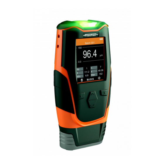
2 Description Measurement view (example) The gages in the MMS Inspection SPG series measure the surface roughness of blasted surfaces easily, Batch 001 quickly and in a nondestructive man- 65.1 ner. Gage construction with an inte- grated measuring probe allows sin- µm gle-hand measurements on flat sam- ples. -
Page 9: Gage
Gage Front of gage Rear of gage 1 Eyelets for a carrying strap 2 Signal lamp to indicate measurement acquisition and limit violations 3 Display 4 Keys, On/off key, for description see page 6 5 Positioning aid for reliable placement of the gage on the surface 6 Probe tip 7 USB port 8 Battery compartment cover... -
Page 10: Keys
Keys There are 4 keys for operating the gage. The bottom line of the display always shows the functions of the 4 keys (see illustration below). The assignment depends on the opened menu page. The function shown on the display is assigned to the key directly underneath (example). key has two functions: •... - Page 11 Batch MEASURE > Switch to Measurement view Modify > Tolerance Limits > Activation of limit monitoring and setting of the limits Settings and en- tries for the Batch Infos opened batch View Settings > Measurement View Batch Statistic View Block View Block Size >...
- Page 12 Probe Settings > Raw data from probe Line frequency settings About > Information about software version and probe as well as legal informa- tion such as copyright, data protec- tion conditions, enhanced labeling Inspection SPG High ®...
- Page 13 2.4.1 Gage concept In order to measure, a batch (file) must be created in the gage for each appli- cation. The calibration 001, which serves as a reference for each batch, is saved in the gage. A description of the expression measuring application, and the terms batch and calibration can be found in Chapter "Glossary".
- Page 14 Inspection SPG High ®...
-
Page 15: Technical Data
Data Sheet ® Inspection SPG Surface profile measurement according to ASTM D4417, Method B Technical Data Easy and convenient operation Compact and robust case Scale 1:1... - Page 16 Description The gage models MMS Inspection SPG measure the depths of surface profiles easily, quick, non-destructively and with the precision that is typical for all Fischer instruments. The SPG gages measure the peak-to-valley distances according ASTM D4417, Method B. Therefore, measurements of the depths of surface profiles by using the SPG gages are conform to many standards and guidances, e.g., SSPC-PA17.
- Page 17 Data transfer • USB: Data transfer of single readings to a PC, Data import to MSExcel via PC-Datex soft- ware; You can gratis download the PC-Datex program from Fischer-Homepage Bluetooth/WiFi only available in gage variant • Bluetooth/WiFi: Data transfer of measurements and data transfer of batches to App PHA-...
- Page 18 Trueness* 000,… 100 µm: ≤ 3 µm 0.94,… 13.94 mils: ≤ 0.12 mils Based on Fischer factory calibration standards, 20 °C (68 °F) for specimen temperature and 100 … 500 µm: ≤3 % of nominal value 3.94 … 19.69 mils: ≤3 % of nominal value 20 …...
- Page 19 Repeatability Precision* 100 … 100 µm: ≤ 1.5 µm 0.94,… 13.94 mils: ≤ 0.06 mils Based on Fischer factory calibration standards, 5 single readings per standard, 20 °C (68 °F) 100 … 500 µm: ≤ 1.5 % of reading 3.94 … 19.69 mils: ≤ 1.5 % of reading specimen temperature and 20 …...
-
Page 20: Set Up
3 Set up Installing batteries Switching on the gage ► Press the key for approx. 1 s. ► Measurement in air: Hold the gage in your hand and press The display shows the main menu or measurement view for the batch that was open at shut- down. -
Page 21: Getting Started
4 Getting started All the settings relevant to measuring the height of surface profile of a sam- Batch 001 and the measured readings 65.1 themselves are saved in a file. Such a file is called a batch. µm In the batch, you define the measure- ment procedure, e.g. -
Page 22: Settings For Measurement
5 Settings for measurement In order to measure, you need to create and open a batch (measuring appli- cation file). In a batch, you define the measuring application and settings for the measurement procedure, e.g. specification limit monitoring or grouping of measured readings in measurement blocks during the measurement. -
Page 23: Visual Inspection Of Probe Tips
Visual inspection of probe tips Although the probe tip is produced from wear-resistant material, it can become damaged during the measurement. The probe tip wears over time and should be replaced after approx. 20,000 measurements. To prevent faulty measure- ments, the probe tips should therefore be visually inspected at regular intervals. When to perform •... -
Page 24: Creating A New Batch
Creating a new batch Each batch contains some presets for the measurement procedure. The preset selection is based on the requirements in a directive/standard or according to customer specifications. Before you start • The gage is switched on ( key) Creating a new batch 1. -
Page 25: Opening A Batch
Opening a batch Before you start • The gage is switched on ( key) Opening an existing batch 1. Main Menu () > Batches > OK 2. Select the desired batch from the list: 3. OK 4. MEASURE > OK 5. -
Page 26: Measurement
6 Measurement Use the device model MMS Inspection SPG to measure the height of surface profiles. The probe measures the peak-to-trough height differences according to ASTM 4417, Method B. The gage is therefore suitable for height measure- ments of surface profiles according to various directives and guidelines, such as SSPC-PA17. -
Page 27: Measurement - Procedure
Measurement - procedure 1 Place the gage 2 Measurement acqui- 3 Lifting the gage sition Place the gage on the sur- Lift the gage from the sur- face. face. The measurement acquisition is reported audibly and also by the illumination of the sig- nal lamp. -
Page 28: Calibration
7 Calibration For a correct measurement, the gage must be adjusted to the extreme values of zero and "maximum height" (= air value). This is done by means of a cali- bration. The extreme and height values are recorded using a glass plate and one or two calibration shims in order to compensate the influences for future measurements. - Page 29 7.2.1 Calibration - procedure 1. Open the calibration: (in the measurement display) 2. Follow the routine and perform the calibration steps displayed (air value and zero). In this regard, refer to the descriptions in the sections "Air value calibration step", page 25 and "Zero calibration step", page 26. 3.
- Page 30 7.2.3 Zero calibration step Measurements on the glass plate from scope of supply. Required material • Glass plate 605-306 from scope of supply Procedure – Zero calibration step Perform 5 to 10 measurements on the glass plate. A Placing the gage C Lifting the gage B Measurement acquisi- tion...
- Page 31 Display description - Zero calibration step 1 Name of calibration Calibration 001 2 Schematic illustration of the current calibration step 3 Current calibration step 4 Progress display of the calibration steps (example of 3 calibration steps, calibration step 1 current) Zero 5 Currently measured reading -3.8...
- Page 32 7.2.4 Foil calibration step (calibration shim) Measurements on the calibration shim (foil) located on the glass plate directly. Required material • Calibration shim(s) from scope of supply. The hole in the shim marks the specified measuring area. • Glass plate from scope of supply Procedure –...
- Page 33 Perform 5 to 10 measurements with the calibration shim. A Placing the gage B Measurement acquisi- C Lifting the gage tion Place the gage on the sur- Lift the gage from the sur- face. The probe tip must be face. The measurement acquisition touching the glass plate is reported by a beep and...
- Page 34 Take the calibration shim from the glass plate Return the calibration shim (1/2) to the protective sleeve. Calibration shim Glass plate To calibrate with 2 calibration shims, repeat the entire foil calibration step (steps 1 to 4) with the second foil. Display description - Foil calibration step (calibration shim) 1 Name of calibration Calibration 001...
-
Page 35: Data Transfer
You can download the app for free from the Google Play Store or Apple App Store. • Single readings in an Excel file via PC-Datex, see page 33 You can download the program PC-Datex for free from the Fischer-Home- page. Transfer batch files in the PHASCOPE PAINT app Before you start •... - Page 36 What you can do next • Use the PHASCOPE PAINT app to export the data as follows: • CSV file, for measurement blocks, e.g., for import to MS Excel. Date and time of measurement block creation and measurement capture, single readings, tolerance specification limits, if in the selected appli- cation set, are always exported.
-
Page 37: Transfer Single Readings Online To An Excel File Via Pc-Datex
Information on the data import and further processing can be found in the corresponding program manuals. You can download the program PC-Datex for free from the Fischer-Home- page. Before you start •... - Page 38 Finish data transfer ► PC: In the PC-Datex Add-In tap on button Cancel of the PC-Datex window What can you do next • Open another batch, see page 21 • Make further measurements with the gage, see page 22 • Delete readings of the open batch in the gage: Main menu (v) >...
-
Page 39: Assigning/Changing Batch Names
9 Assigning/changing batch names Assign a unique name for the batch. Keep in mind that many batch files are stored in the gage. A unique name makes the selection process easier. Procedure 1. Main Menu () > Batches > OK 2. -
Page 40: Replacing The Probe Tip
10 Replacing the probe tip Although the probe tip is produced from wear-resistant material, it can become damaged during the measurement. Furthermore, the probe tip wears over time due to mechanical loading. When to perform • We recommend after approx. 20,000 measurements •... - Page 41 5. Place the new probe tip (with felt ring attached) in the housing. 6. Using exchange-tool 605-248, care- fully and without using additional force, screw the new probe tip into the housing as far as it will go. 7. Perform a calibration as described on page 24.
-
Page 42: Glossary
11 Glossary ASTM 4417, Method B Measurement method for measuring the height of surface profile. The peak-to- trough height differences according to standards are measured. The profile height value is determined in 10 measurements. Depending on the directive or guideline according to which the test is being carried out, you can set in the gage which value of the 10 measurements is to be displayed and saved. - Page 43 • Calibration shim, thin shim of a specified thickness. An adjustment to the corresponding profile height value is performed for each calibration foil thickness. Calibration A calibration is a reference measurement, which adjusts the gage to the two extreme values of zero and "maximum height" (air value). You can run the cal- ibration with up to 2 calibration shims (from the scope of supply).
- Page 44 Zero see under Calibration standards Inspection SPG High ®...
-
Page 45: Glossary - Display Symbols
11.1 Glossary - Display symbols Batches menu, contains a list of batches already created and the New function for creating a new batch. Batch Modify menu, contains a list of alterable batch settings Statistics menu, contains statistics displays for the open batch. •... - Page 46 Confirm the message/information Opens a settings window, e.g. for setting the nominal value of the cali- bration shim used Cancels the setting process and returns to the previous menu page Forward, skips the next step in the routine Back • Returns to the previous menu page, altered settings are applied •...
- Page 47 Number of measured readings above the upper specification limit >USL Range R equals the difference between the largest measured reading (maximum) and the smallest measured reading (minimum) in a series of measurements Standard deviation from the mean value Lower specification limit Number of measured readings below the lower specification limit <LSL Coefficient of variation, percent variation of a series of measurements,...
-
Page 48: About
12 About In this menu you will find all device information, information about the device status, the software and legal information. Navigation : Select the desired parameter/batch : Confirms selection : Scrolls forward through the page : Exit page, scrolls back to the previous page Call up menu ►... -
Page 49: Legal Informations
13 Legal Informations In this chapter you will find all statements on country-specific regulations and directives 13.1 USA, FCC (Federal Communications Commission) FCC ID: 2ATFE-MMSINSPEC00 FCC Regulations This device complies with Part 15 of the FCC Rules. Operation is subject to the following two conditions: (1) this device may not cause harmful interference, and (2) this device must accept any interference received, including interfer- ence that may cause undesired operation. - Page 50 Changes or modifications not expressly approved by the party responsi- ble for compliance could void the user‘s authority to operate the equip- ment. Information about Specific Absorption Rate (SAR) This device is designed and manufactured not to exceed the emission limits for exposure to radio frequency (RF) energy set by the Federal Communications Commission of the United States.
- Page 52 Coating Thickness Material Analysis Nanoindentaion Material Testing...
Need help?
Do you have a question about the MMS Inspection SPG Series and is the answer not in the manual?
Questions and answers