
Related Manuals for FISCHER MA15F A Series


Summary of Contents for FISCHER MA15F A Series
- Page 1 Operation manual MA15F ... A/B/C/D Diaphragm manometer for explosive areas Gas explosion protection zone 1 and 2, gases and vapours Dust explosion protection zone 21 and 22, dry dusts...
- Page 2 Great care was taken when compiling the texts and illustrations; Nevertheless, errors cannot be ruled out. The company FISCHER Mess- und Regeltechnik GmbH will not accept any legal responsibility or liability for this.
-
Page 3: Table Of Contents
FISCHER Mess- und Regeltechnik GmbH Table of Content Table of Content 1 Safety information......................4 1.1 General........................... 1.2 Personnel Qualification ......................1.3 Risks due to Non-Observance of Safety Instructions............. 1.4 Safety Instructions for the Operating Company and the Operator ......... -
Page 4: Safety Information
1 | Safety information FISCHER Mess- und Regeltechnik GmbH 1 Safety information 1.1 General This operating manual contains basic instructions for the installation, operation and maintenance of the device that must be followed without fail. It must be read by the installer, the operator and the responsible specialist personnel be- fore installing and commissioning the device. -
Page 5: Unauthorised Modification
FISCHER Mess- und Regeltechnik GmbH Safety information | 1 The instrument must be decommissioned and secured against inadvertent re- operation if a situation arises in which it must be assumed that safe operation is no longer possible. Reasons for this assumption could be: •... -
Page 6: Pictogram Explanation
1 | Safety information FISCHER Mess- und Regeltechnik GmbH 1.8 Pictogram explanation DANGER Type and source of danger This indicates a direct dangerous situation that could lead to death or serious injury (highest danger level). 1. Avoid danger by observing the valid safety regulations. -
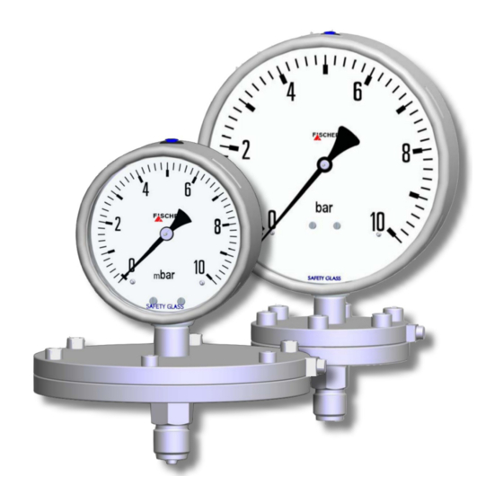
Page 7: Product And Functional Description
FISCHER Mess- und Regeltechnik GmbH Product and functional description | 2 2 Product and functional description 2.1 Delivery scope • Diaphragm manometer MA15 • Operating Manual 2.2 Product summary Manometer casing Contact element Contact element Scale Flange Ground connection Connecting shanks MA15F ... -
Page 8: Intended Use
2 | Product and functional description FISCHER Mess- und Regeltechnik GmbH 2.2.1 Type plate This type plate serves as an example of the information that is stated. The data shown is purely fictive, but does correspond to the actual conditions. For more information, please see the order code at the end of these instructions. -
Page 9: Function Diagram
FISCHER Mess- und Regeltechnik GmbH Product and functional description | 2 2.4 Function diagram Fig. 4: Function diagram 1 Motion train 2 Connecting rod 3 Flange 4 Diaphragm 2.5 Design and mode of operation The measuring element, the concentric corrugated diaphragm, is clamped between two flanges and the medium is applied on one side. -
Page 10: Assembly
3 | Assembly FISCHER Mess- und Regeltechnik GmbH 3 Assembly 3.1 Generalities The instrument may only be installed and commissioned by specialized person- nel familiar with the installation, commissioning and operation of this product. Specialized personnel are persons who can assess the work they have been assigned and recognize potential dangers by virtue of their specialized training, their skills and experience and their knowledge of the pertinent standards. - Page 11 FISCHER Mess- und Regeltechnik GmbH Assembly | 3 G½ Manometer connection G½ ca. 180 AF27 Ø20 Connection spigot according to Ø20 DIN EN 837-1 G½ Round shape U-shape Fig. 6: Siphon MZ1### • The transmitter must be positioned below the measuring point for liquid measurements.
-
Page 12: Electrical Connections
3 | Assembly FISCHER Mess- und Regeltechnik GmbH b) Settable damping reactor In operating mode, the damping throttle must be set so that the output signal follows the pressure changes with a delay. G½ Manometer connection AF27 Setting screw Connection spigot according to DIN EN 837-1 G½... -
Page 13: Use In Areas At Risk Of Explosion
FISCHER Mess- und Regeltechnik GmbH Assembly | 3 3.3.3 Rotation angle transducer acc. to data sheet KE09 For more technical information about the rotation angle transducer, please see the data sheet KE09. You can request the data sheet on request or via our web- server www.fischermesstechnik.de. - Page 14 3 | Assembly FISCHER Mess- und Regeltechnik GmbH 3.4.2 Diaphragm manometer with magnetic spring contacts MA15 … 1B II 2G Ex h IIC T4 Gb Simple electric operating equipment acc. to EN60079-11 sec: 5.7 in explosive areas Zone 1 and 2.
- Page 15 FISCHER Mess- und Regeltechnik GmbH Assembly | 3 3.4.3 Diaphragm manometer with inductive contacts MA15 … 1C II 2G Ex h IIC T4 Gb II 2D Ex h IIIC T95°C Db Explosive areas Zone 1 and 2, and 21 and 22, risk from gases and dry dust.
- Page 16 3 | Assembly FISCHER Mess- und Regeltechnik GmbH 3.4.4 Diaphragm manometer with rotation angle transducer MA15 … 2D II 2G Ex h IIC T4 Gb Explosive areas Zone 1 and 2, risk from gases. Rotation angle transducer: KE0905#9 Allowed temperatures: •...
-
Page 17: Commissioning
FISCHER Mess- und Regeltechnik GmbH Commissioning | 4 4 Commissioning 4.1 General All electrical supply, operating and measuring lines, and the pressure connec- tions must have been correctly installed before commissioning. All supply lines are arranged so that there are no mechanical forces acting on the device. -
Page 18: Switch Point Setting
4 | Commissioning FISCHER Mess- und Regeltechnik GmbH 4.3 Switch point setting There is an adjustment lock attached to the front pane of the measuring unit on units with installed limit signal encoders. Using the detachable adjustment key, the contacts attached to the target indicators can be set to any point along the scale. -
Page 19: Servicing
FISCHER Mess- und Regeltechnik GmbH Servicing | 5 5 Servicing 5.1 Maintenance To ensure reliable operation and a long service life, we recommend carrying out the following test on a regular basis: • Check the reading. • Checking the switch function in connection with the downstream compon- ents. -
Page 20: Accessories
Please see here the data sheet MZ measuring devices accessories. Here you will find more detailed information about the technical data and the order codes of the accessory parts MZ. You can request the data sheet on request or via our webserver www.fischer- messtechnik.de. 5.6 Disposal... -
Page 21: Technical Data
FISCHER Mess- und Regeltechnik GmbH Technical Data | 6 6 Technical Data 6.1 Standard version The measuring variable is pressure and/or under-pressure in gaseous, liquid, aggressive, highly viscous or soiled media. The diaphragm manometer fulfils the requirements of the standard EN 837-3. -
Page 22: Options
6 | Technical Data FISCHER Mess- und Regeltechnik GmbH Protection IP66 acc. to EN 60529 / IEC 60529 Materials Housing CrNi Steel 1.4404 Motion train CrNi steel 1.4301 Dial face and needle Aluminium (painted) Inspection disk Safety laminated glass Connecting port (contact with medium) CrNi-steel 1.4404 (AISI 316L) Connection flange (contact with me- CrNi-steel 1.4404 (AISI 316L) -
Page 23: Dimensional Drawings
FISCHER Mess- und Regeltechnik GmbH Technical Data | 6 Measuring system • O applications 'Oil and grease' In compliance with the requirements of the Chemical Professional Associ- ation, all parts that come into contact with the medium are cleaned (see or- der code filling fluids) •... - Page 24 6 | Technical Data FISCHER Mess- und Regeltechnik GmbH 6.3.2 Model with contacts Ød1 Fig. 13: Dimension drawing MA15F with contacts Housing Ød1 Bayonet ring housing Safety housing 6.3.3 Process connection 6.3.3.1 Version with collar flange The dimensions stated apply for all housing models NG100 and NG160.
- Page 25 FISCHER Mess- und Regeltechnik GmbH Technical Data | 6 6.3.3.2 Version with DIN connection flange The dimensions stated apply for all housing models NG100 and NG160. Ød2 ØD Fig. 15: Connection flange Measuring range ≤ 400 ØD Ød2 mbar Ø Thread Measuring range ≥...
- Page 26 6 | Technical Data FISCHER Mess- und Regeltechnik GmbH 6.3.3.4 Connecting shanks DIN 837 ANSI B1.20.1 Centring pin Fig. 16: Connecting shanks G (Thread) G¼B G⅜B G½B 17.5 M20 x 1.5 17.5 ¼-18 NPT ½-14 NPT 26/48 BA_EN_MA15_ATEX...
-
Page 27: Order Codes
FISCHER Mess- und Regeltechnik GmbH Order Codes | 7 7 Order Codes Code no. 10 11 12 Type [2.3] Measuring range 0 … 16 mbar 0 … 25 mbar 0 … 40 mbar 0 … 60 mbar 0 … 100 mbar 0 …... - Page 28 7 | Order Codes FISCHER Mess- und Regeltechnik GmbH Rated pressure of the measuring system 10 bar (Measuring ranges ≤ 250 mbar) 40 bar (Measuring ranges ≥ 400 mbar) Design of the measuring system CrNi Steel 1.4404 CrNi steel 1.4404 with diaphragm in Hastelloy C CrNi steel 1.4404 with PFA coating...
- Page 29 FISCHER Mess- und Regeltechnik GmbH Order Codes | 7 [10] Special functions Zero-point correction with setting screw Zero-point correction micro adjust- ment indicator Zero-point correction with setting Adjustable marker needle screw ♣) Zero-point correction with setting Resettable drag needle screw...
-
Page 30: Accessories
Pressure gauge Shut-off valve acc. to DIN 16270/16271 Journal/ socket G1/2 MZ6### Pressure gauge double valve acc. to DIN 16272 Journal/socket G1/2 The data sheet is available on request or from our web server www.fischer- messtechnik.de. Order no. Designation Type... - Page 31 FISCHER Mess- und Regeltechnik GmbH Order Codes | 7 Order no. Designation Type 05003093 Display / Programming front 4501 Communication interface for setting the oper- ating parameters for supply isolating amplifi- ers and pulse isolators. • The device may only be used in safe areas.
-
Page 32: Attachments
8 | Attachments FISCHER Mess- und Regeltechnik GmbH 8 Attachments 8.1 EU Declarations of conformity Fig. 17: CE_EN_MA15F_0A 32/48 BA_EN_MA15_ATEX... - Page 33 FISCHER Mess- und Regeltechnik GmbH Attachments | 8 BA_EN_MA15_ATEX 33/48...
- Page 34 8 | Attachments FISCHER Mess- und Regeltechnik GmbH Fig. 18: CE_EN_MA15F_1B_page 1 34/48 BA_EN_MA15_ATEX...
- Page 35 FISCHER Mess- und Regeltechnik GmbH Attachments | 8 Fig. 19: CE_EN_MA15F_1B_page 2 BA_EN_MA15_ATEX 35/48...
- Page 36 8 | Attachments FISCHER Mess- und Regeltechnik GmbH Fig. 20: CE_EN_MA15F_1C_page 1 36/48 BA_EN_MA15_ATEX...
- Page 37 FISCHER Mess- und Regeltechnik GmbH Attachments | 8 Fig. 21: CE_EN_MA15F_1C_page 2 BA_EN_MA15_ATEX 37/48...
- Page 38 8 | Attachments FISCHER Mess- und Regeltechnik GmbH Fig. 22: CE_EN_MA15F_2D_page 1 38/48 BA_EN_MA15_ATEX...
- Page 39 FISCHER Mess- und Regeltechnik GmbH Attachments | 8 Fig. 23: CE_EN_MA15F_2D_page 2 BA_EN_MA15_ATEX 39/48...
-
Page 40: Ukca Declarations Of Conformity
8 | Attachments FISCHER Mess- und Regeltechnik GmbH 8.2 UKCA Declarations of Conformity Fig. 24: UKCA_EN_MA15_0A 40/48 BA_EN_MA15_ATEX... - Page 41 FISCHER Mess- und Regeltechnik GmbH Attachments | 8 BA_EN_MA15_ATEX 41/48...
- Page 42 8 | Attachments FISCHER Mess- und Regeltechnik GmbH Fig. 25: UKCA_EN_MA15_1B_Page_1 42/48 BA_EN_MA15_ATEX...
- Page 43 FISCHER Mess- und Regeltechnik GmbH Attachments | 8 Fig. 26: UKCA_EN_MA15_1B_Page_2 BA_EN_MA15_ATEX 43/48...
- Page 44 8 | Attachments FISCHER Mess- und Regeltechnik GmbH Fig. 27: UKCA_EN_MA15_1C_Page_1 44/48 BA_EN_MA15_ATEX...
- Page 45 FISCHER Mess- und Regeltechnik GmbH Attachments | 8 Fig. 28: UKCA_EN_MA15_1C_Page_2 BA_EN_MA15_ATEX 45/48...
- Page 46 8 | Attachments FISCHER Mess- und Regeltechnik GmbH Fig. 29: UKCA_EN_MA15_2D_Page_1 46/48 BA_EN_MA15_ATEX...
- Page 47 FISCHER Mess- und Regeltechnik GmbH Attachments | 8 Fig. 30: UKCA_EN_MA15_2D_Page_2 BA_EN_MA15_ATEX 47/48...
- Page 48 Mess- und Regeltechnik GmbH Bielefelder Str. 37a D-32107 Bad Salzuflen Tel. +49 5222 974-0 Fax +49 5222 7170 www.fischermesstechnik.de info@fischermesstechnik.de Technische Änderungen vorbehalten. Subject to technical changes. Sous réserve de modifications techniques.
Need help?
Do you have a question about the MA15F A Series and is the answer not in the manual?
Questions and answers