Advertisement

Guidelines
®
DELTASCOPE
FMP10
®
ISOSCOPE
FMP10
®
DUALSCOPE
FMP20
Coating Thickness
Material Analysis
Microhardness
Material Testing

Advertisement

Table of Contents
loading
Need help?

Need help?

Do you have a question about the DELTASCOPE FMP10 and is the answer not in the manual?

Questions and answers

Subscribe to Our Youtube Channel

Summary of Contents for FISCHER DELTASCOPE FMP10

  • Page 1 Guidelines ® DELTASCOPE FMP10 ® ISOSCOPE FMP10 ® DUALSCOPE FMP20 Coating Thickness Material Analysis Microhardness Material Testing...
  • Page 3: Table Of Contents

    Please study the safety information in the operator’s manual as well. Observe the warnings and hints in the operator’s manual in order to avoid injury and damage to the instrument! Table of Contents 1 Notes ......... . . 1 2 Areas of Application .
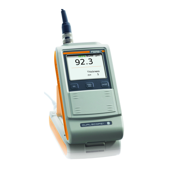
  • Page 4: Notes

    Notes This brief guide offers a first, brief overview of your instrument's operation and provides quick steps towards your first measurement results. An extensive oper- ator's manual can be found on the CD-ROM that is supplied with the instrument. The following symbols are used in this brief guide. Indicates safety information referring to danger for per- sons and warnings regarding damage to the measuring instrument or to accessories.
  • Page 5: Areas Of Application

    Areas of Application The instrument is used for coating thickness measurements. The following table lists the measurement methods that are used in the various FMP instruments. Measurement method / Instrument Area of application Probe type Determination of the thickness of non-magnetic Magnetic Induction Method coatings on steel or iron.
  • Page 6: Description Of The Instrument

    Description of the Instrument Probe connector socket, Page 8 LCD Display, Page 4 Keys for directly retrieving functions, Page 5 USB port for connecting a ON/OFF key to turn the in- strument on or off, Page 9 Cover; additional function keys can be found under the cover, Page 5...
  • Page 7: Lcd Display

    LCD Display The LCD display consists of several display elements. When powering up the instrument using ON/OFF, all display elements will appear briefly at the same time. Display Explanation element A normalization is performed (on the uncoated specimen = base material). A calibration is carried out.
  • Page 8: Control Panel Key Functions

    Display Explanation element Hourglass: Measurements are currently not possible because an instrument-internal routine is running. Information lines: ...SCOPE ... Instrument type FKA... Instrument-internal software version Control Panel Key Functions Function Deletes the last measured reading Returns to the previous menu or Cancels the procedure FINAL-RES Retrieves the final result...
  • Page 9: Probe Handling

    Probe handling Always hold the probe at its grip sleeve (right figure). Always place the probe gently and at a right angle on the specimen surface. Slide the grip sleeve to the specimen surface such that the sleeve rests on the specimen (center and bottom Figure, right).
  • Page 10: System Setup

    System Setup Install the batteries/rechargeable batteries Use only type MIGNON, 1.5 V, LR6 - AA - AM3 - MN1500 batteries or 4 individual rechargeable batteries 1.2 V 2400 mAh Type AA. Using other batteries may lead to instrument damage. Use only non-damaged batteries/rechargeable batteries. Observe the cor- rect polarity when installing the bat-...
  • Page 11: Probe Connection

    Probe connection A measurement probe must be connected to the instrument to make coating thick- ness measurements. This must be an appropriate probe suitable for the base ma- terial. Connect probes only when the instrument is off! To turn the instrument off: Press the ON/OFF key on the right side of the control panel.
  • Page 12: Instrument On/Off

    Instrument On/Off Turning the instrument on Detail of the LCD Explanation display Press the ON/OFF key to turn on the instrument. An audible signal will sound. A monitoring routine will run automatically. All display ele- ments of the LCD display will appear briefly at the same time ( Page 4).
  • Page 13 Measurement Method of the Connected Probe Display Explanation [ NF/Fe] Magnetic induction probe connected. [ NC/NF] Eddy current probe connected [NF/Fe NC/NF] Dual probe connected and dual method [both] set (i.e., in the open application, both measurement methods can be used to make measurements).
  • Page 14: Adjusting Instrument And Probe

    Adjusting Instrument and Probe The following options exist after the instrument is turned on: The instrument recognizes the connected probe. The measurement screen appears on the LCD display. The display of the measurement method does not flash. In this case, you can start immediately making measurements. If the instrument is turned on and a probe other than the one used last is connected, the following display will appear: “W006 Probe changed”.
  • Page 15: Normalization

    Normalization With the normalization, a new zero point is established for the calibration curve and stored in the instrument. Required materials Reference part: Uncoated part from the production. Procedure Key sequ. / Detail of the LCD Explanation Action display ZERO Use ZERO to start the normalization.
  • Page 16: Corrective Calibration

    Key sequ. / Detail of the LCD Explanation Action display ENTER The new characteristic will be computed automatically and stored. The instrument is again ready to make measurements. Corrective Calibration Options One-point calibration with one calibration standard: A new zero point and one additional point are established for the calibration curve and stored in the in- strument.
  • Page 17 Procedure Key sequ. / Detail of the LCD Explanation Action display Use CAL to start the corrective calibration. CAL appears and remains on the LCD dis- play while the corrective calibration is per- formed. [s]: Standard deviation [n]: Number of measurements [base material (Fe/NF)]: Measurements should be performed on an uncoated spec- imen (Fe or NF display for the type of base...
  • Page 18 Key sequ. / Detail of the LCD Explanation Action display Place the calibration standard 1 (in the ex- ample with a thickness of 23.7 µm) on the uncoated specimen and perform measure- ments. Make individual measurements at various points of the reference area. Displayed is the mean value of all measurements per- formed for this step.
  • Page 19: Reference Measurements

    Reference Measurements Perform several reference measurements by measuring the thickness of a calibration standard placed on the uncoated reference area in order to verify a correct normalization or corrective calibration. The thickness of the stan- dard should be close to the nominal thickness value of the coating to be mea- sured.
  • Page 20: Service Functions

    Service Functions How to access the “Service function” menu Key sequ. / Detail of the LCD Explanation Action display ON/OFF Use ON/OFF to turn the instrument on 5 x ENTER After pressing ENTER 5 times, the identifi- cation number 157 appears on the LCD display.
  • Page 21 Service Functions Overview Service menu Functions System Language Contrast Lighting Autom. off Initialization Send free-running mode Instrument mode Restr. Mode Analog display Measurement Audible signal Measurement effect External start Measuring mode - Standard/ Area measurement/Automatic measurement Display dual method Units metric/imperial Storage mode save/don't save/delete on off...
  • Page 22 Moosmattstrasse 1 · Postfach · CH-6331 Hünenberg : (+41) 41 785 08 00 · Fax: (+41) 41 785 08 01 switzerland@helmutfischer.com Valid for Helmut Fischer AG and www.helmutfischer.com Branch Offices Branch Offices of Helmut Fischer AG, Switzerland: SPAIN ITALY JAPAN FISCHER INSTRUMENTS, S.A. HELMUT FISCHER S.R.L.

This manual is also suitable for:

Dualscope fmp20Isoscope fmp10

Table of Contents

Save PDF