
Related Manuals for FISCHER MD-1a


Summary of Contents for FISCHER MD-1a
- Page 2 Table of Contents FISCHER MODEL MD-1a Galvanic Unit Technical Reference Manual CONTENTS Description ...............Page 2 Installation..............Page 2 Panel Controls ............Page 3 Device Specifications ..........Page 4 Device Maintenance ..........Page 4 Device Inspection .............Page 5 Assembly Parts List ..........Page 8 Schematic Diagram ..........Page 9 FOR PROFESSIONAL USE ONLY Rev.
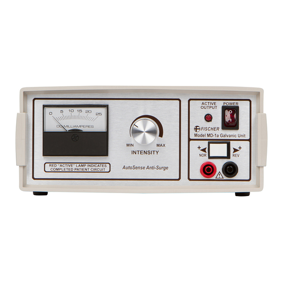
- Page 3 MD-1a Galvanic Unit The Model MD-1a Galvanic Unit offers a versatile approach to the use of Galvanic (DC) current in certain medical applications employing anaphoresis, cataphoresis, or iontophoresis. It is designed for use by physicians in a clinic setting, and generates an adjustable, filtered DC current from normal AC line voltage.
- Page 4 Description of Model MD-1a panel controls DC MILLIAMPERE METER This analog meter indicates actual current flow, in DC Milliamperes, through the connected patient circuit. A reading can only be obtained when a resistive load is applied between output jacks and the INTENSITY knob is adjusted.
- Page 5 Application #249247 Note: Output specifications measured at 115VAC line voltage DEVICE MAINTENANCE The Model MD-1a does not require specific periodic maintenance beyond regular inspection of the device and accessory cords. Refer to the following page for recommended inspection procedures. Page 4...
- Page 6 DEVICE INSPECTION The factory recommends inspecting this device according to the following schedule. Inspections may be performed at other intervals as required by maintenance personnel at the installation site, but in no event should the interval between inspections exceed 24 months.
- Page 7 DEVICE INSPECTION Electrical Device Inspection Period: Annually (12 months) Line Voltage, Ground Integrity: ◊ Measure line voltage supplied to the device . Accept: 105-120 VAC ◊ Confirm reliable ground connection by ensuring line receptacle is 3-prong grounded type and ground integrity is intact. Accept: Ground OK ◊...
- Page 8 Plug line cord into a grounded receptacle and press the bottom edge of the POWER • switch to turn on the MD-1a (red portion of power switch will be visible). Note that the red “ACTIVE” LED will NOT be lit unless a patient circuit is completed between the Output Jacks and current is flowing.
- Page 9 65-0082 10 Pin Contact Housing 1.00 66-0014 #10 Red Crimp Lug 3.00 67-0020 Hospital Grade Line Cord 1.00 68-0024B MD-1a PCB Rev B 1.00 69-0004 3/8 Amp Slo-Blow Fuse 1.00 77-0004 Varflex #6 HO tubing 1.50 81-0048 TS-1/MD-1 Cabinet 1.00...
- Page 10 Page 9...
Need help?
Do you have a question about the MD-1a and is the answer not in the manual?
Questions and answers