
Related Manuals for Shel lab SMI2


Summary of Contents for Shel lab SMI2
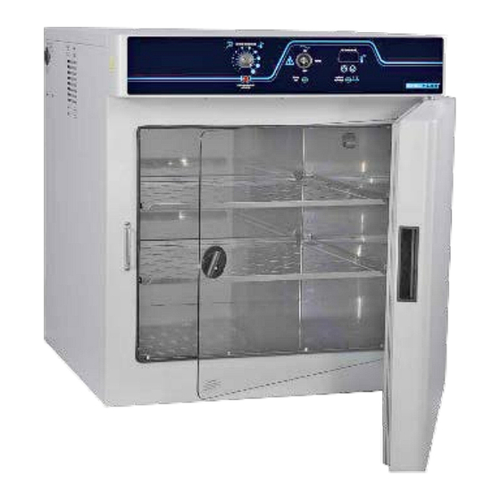
- Page 1 SMI INCUBATORS 100 – 120 Voltage Installation - Operation Manual SMI2 SMI6 SMI7 SMI11 SMI12...
- Page 2 Pictured on cover: SMI6 SMI11 SMI12 (2 Stacked SMI6s) SMI2 SMI7 P a g e...
- Page 3 Installation and Operation Manual Part Number: 4861572-1 Revised: March 2, 2018 SHEL LAB is a brand of Sheldon Manufacturing, INC. Safety Certifications These units are CUE listed by TÜV SÜD as incubators for professional, industrial, or educational use where the preparation or testing of materials is done at an ambient air pressure range of 22.14 – 31.3 inHg (75 –...
-
Page 4: Table Of Contents
TABLE OF CONTENTS INTRODUCTION ................................ 5 Read this Manual ..................................5 Safety Considerations and Requirements ........................5 Contacting Assistance ................................6 Temperature Reference Sensor Device .......................... 6 Engineering Improvements..............................6 RECEIVING YOUR UNIT ............................7 Inspect the Shipment ................................7 Recording Data Plate Information ............................. -
Page 5: Introduction
INTRODUCTION Thank you for purchasing a SHEL LAB Incubator. We know you have many choices in today’s competitive marketplace when it comes to constant temperature equipment. We appreciate you choosing ours. We stand behind our products and will be here for you if you need us. -
Page 6: Contacting Assistance
Therefore, some changes, modifications, and improvements may not be covered in this manual. If your unit’s operating characteristics or appearance differs from those described in this manual, please contact your SHEL LAB dealer or customer service representative for assistance. -
Page 7: Receiving Your Unit
5. Verify that the correct number of accessory items have been included. Included accessories Model Shelves Shelf Slides Leveling Feet Power Cord SMI2, SMI7 SMI6 SMI11 SMI12 6. Carefully check all packaging for accessories before discarding. P a g e... -
Page 8: Recording Data Plate Information
RECEIVING YOUR UNIT ECORDING LATE NFORMATION The data plate contains the incubator model number and serial number. Tech Support will need this information during any support call. Record it below for future reference. The data plate is located on the top right corner of the incubation chamber door interior. •... -
Page 9: Installation
INSTALLATION NSTALLATION ROCEDURE HECKLIST Carry out the procedures and steps listed below to install the incubator in a new workspace location and prepare it for use. All procedures are found in the Installation section of this manual. Pre-Installation Check that the required ambient condition for the unit are met, page 10 ... -
Page 10: Required Ambient Conditions
Operating these units outside of these conditions may adversely affect its incubator temperature stability and effective operating range. For conditions outside of those listed above, please contact your SHEL LAB distributor to explore other options suited to your laboratory or production environment. -
Page 11: Power Source Requirements
Always find and fix the cause of a blown fuse prior to putting the unit back into operation. • Fuse types • SMI7 and SMI11 - 250V T10 amp, 5x20mm SMI2, SMI6, SMI12 - 250V T6.3A, 5x20mm 11 | P a g e... -
Page 12: Lifting And Handling
INSTALLATION IFTING AND ANDLING The unit is heavy. Use appropriate lifting devices that are sufficiently rated for these loads. Follow these guidelines when lifting the unit. Lift the unit only from its bottom surface. • Doors, handles, and knobs are not adequate for lifting or stabilization. •... -
Page 13: Deionized And Distilled Water
INSTALLATION EIONIZED AND ISTILLED ATER Do not use deionized water to clean or humidify the incubator. Use of deionized water may corrode metal surfaces and voids the warranty. The manufacturer recommends the use of distilled water in the resistance range of 50K Ohm/cm to 1M Ohm/cm, or a conductivity range of 20.0 uS/cm to 1.0 uS/cm, for cleaning and humidifying applications. - Page 14 INSTALLATION 14 | P a g e...
-
Page 15: Graphic Symbols
GRAPHIC SYMBOLS The unit is provided with multiple graphic symbols on its exterior. The symbols identify hazards and the functions of the adjustable components, as well as important notes in the user manual. Symbol Definition Consult the user manual. Consulter le manuel d'utilisation Temperature display Indique l'affichage de la température Over Temperature Limit system... - Page 16 GRAPHIC SYMBOLS 16 | P a g e...
-
Page 17: Control Panel Overview
CONTROL PANEL OVERVIEW Figure 1: Control Panel Over Temperature Limit Control (OTL) The Set Over Temperature dial sets the temperature limit at which the incubator cuts off heating in the incubation chamber. The red Over Temp Activated light illuminates when the OTL system is rerouting power away from the heating elements. - Page 18 CONTROL PANEL OVERVIEW 18 | P a g e...
-
Page 19: Operation
OPERATION HEORY OF PERATION The SMI general purpose incubators are engineered to provide constant temperature incubation environments. Each unit can obtain a stable, uniform temperature in its chamber, ranging from the room temperature (ambient) +8°C up to 70°C for incubation applications. Each incubator features an inner glass viewing door that allows visual inspection of samples without compromising the chamber temperature environment. -
Page 20: Put The Incubator Into Operation
OPERATION UT THE NCUBATOR INTO PERATION Carry out the following steps and procedures to put the unit into operation after installing it in a new workspace environment. Attach the power cord that came with the unit to the power inlet receptacle on the side of the incubator. -
Page 21: Set The Incubator Temperature Set Point
OPERATION ET THE NCUBATOR EMPERATURE OINT SMI12: Each incubator must be set independently. 1. Set the OTL control to its maximum setting, if not already set to max. Turning the OTL all the way to the right (clockwise) prevents the heating •... -
Page 22: Set The Over Temperature Limit
OPERATION Note: Test the OTL heating cutoff system at least once per year for functionality. ET THE EMPERATURE IMIT The incubator must be operating at your incubation application temperature and must be stable for at least 1 hour prior to setting the OTL. Each incubator OTL must be set independently in the SMI12. 1. -
Page 23: Loading Samples
OPERATION OADING AMPLES Place items on the shelves inside the incubation chamber as evenly spaced as possible. Proper spacing allows for maximum air circulation and a high degree of temperature uniformity. Leave 1 inch (2.5cm) between sample containers and the chamber walls. HAMBER CCESSORY OWER... -
Page 24: Condensation And The Dew Point
OPERATION ONDENSATION AND THE OINT Condensation takes place whenever the humidity level in the incubator chamber reaches the dew point. The dew point is the level of humidity at which the air cannot hold more water vapor. The warmer the air, the more water vapor it can hold. As the level of humidity rises in an incubation chamber, condensate will first appear on surfaces that are cooler than the air temperature. -
Page 25: User Maintenance
USER MAINTENANCE Warning: Disconnect this unit from its power supply prior to performing maintenance or services. Avertissement: Débranchez cet appareil de son alimentation électrique avant d'effectuer la maintenance ou les services. LEANING AND ISINFECTING If a hazardous material or substance has spilled in the unit chamber, immediately initiate your site Hazardous Material Spill Containment protocol. -
Page 26: Minimizing Contamination Exposure
USER MAINTENANCE Disinfecting For maximum effectiveness, disinfection procedures are typically performed after cleaning. Keep the following points in mind when disinfecting the unit. Turn off and disconnect the unit to safeguard against electrical hazards. • Disinfect the unit chamber using commercially available disinfectants that are non-corrosive, •... -
Page 27: Storing The Incubator
USER MAINTENANCE TORING THE NCUBATOR Perform the following steps if the incubator will be out of use for more than 24 hours to prevent microbiological contamination such as fungus or mold. Depower the incubator. 2. Disinfect and clean if required by your laboratory protocol, or if the chamber has been exposed to pathogenic microorganisms. -
Page 28: Calibrate The Temperature Display
USER MAINTENANCE ALIBRATE THE EMPERATURE DISPLAY Performing a temperature display calibration requires a temperature reference device. Please Note: see the Reference Sensor Device entry on page 6 for the device requirements. Each SMI12 incubation chamber must be independently calibrated to its temperature display. Note: Temperature calibrations are performed to match an incubator temperature display to the actual air temperature inside the incubation chamber. - Page 29 USER MAINTENANCE 5) Temperature Stabilization The incubator air temperature must stabilize in order to perform an accurate calibration. Allow the incubator to operate undisturbed with the doors shut for at least 8 hours when • first putting the unit into operation in a new environment. To be considered stabilized, the incubator chamber must operate at your calibration •...
- Page 30 USER MAINTENANCE Temperature Calibration Continued Place the display in its temperature calibration mode. a. Press and hold both the UP and DOWN temperature arrow buttons simultaneously for approximately 5 seconds. b. Release the buttons when the temperature display shows the letters “C O”. The display will begin flashing the current temperature display value.
- Page 31 USER MAINTENANCE Reference Device Compare the reference device reading with the chamber temperature display again. If the reference device and the chamber temperature • display readings are the same or the difference falls within the range of your protocol, the incubator is now calibrated for temperature.
- Page 32 USER MAINTENANCE 32 | P a g e...
-
Page 33: Unit Specifications
We reserve the right to alter technical specifications at all times. EIGHT Model Shipping Net Incubator Weight SMI2 117 lbs. / 53 kg 83.0 lbs. / 37.6 kg SMI6 183 lbs. / 83 kg 158.0 lbs. / 71.7 kg SMI7 198 lbs. -
Page 34: Capacity
UNIT SPECIFICATIONS APACITY Model Feet Liters 56.3 SMI2 166.0 SMI6 184.0 SMI7 10.9 309.0 SMI11 11.7* 332.0* SMI12* *Each chamber EMPERATURE Model Range Uniformity Stability Ambient +8° to 70°C ±0.5° @ 37°C ±0.1°C @ 37°C OWER Model AC Voltage Amperage 100–120... -
Page 35: Parts List
PARTS LIST Description Parts Number Fuse, 6.3 Amp 250V, Shelf, SMI6, SMI12 SMI2, SMI6, SMI12 3300515 5130523 Fuse, 10 Amp 250V Shelf Slide, SMI6, SMI7, SMI1 SMI12 5081201 3300516 Leveling Foot Shelf, SMI7 2700512 5130518 Power Cord 115 volt 15 Amp, 9ft 5 in Shelf Slide, SMI7 (2.86m) NEMA 5-15P... - Page 36 P.O. Box 627 Cornelius, OR 97113 support@sheldonmfg.com sheldonmanufacturing.com 1-800-322-4897 (503) 640-3000 FAX: 503 640-1366...
Need help?
Do you have a question about the SMI2 and is the answer not in the manual?
Questions and answers