
Subscribe to Our Youtube Channel
Related Manuals for Shel lab SCO5W


Summary of Contents for Shel lab SCO5W
- Page 1 WATER-JACKETED CO INCUBATOR 110 – 120 Volts Installation - Operation Manual SCO5W...
- Page 2 P a g e...
- Page 3 110 – 120 Voltage Part Number (Manual): 4861732 Revision: January 2, 2018 SHEL LAB is a brand of Sheldon Manufacturing, INC. Safety Certifications These units are TÜV listed as water jacket incubators for professional, industrial, or educational use where the preparation or testing of materials is done at an ambient air pressure range of 22.14 – 31.3 inHg (75 –...
-
Page 4: Table Of Contents
TABLE OF CONTENTS INTRODUCTION ................................. 7 Read this Manual ..................................7 Safety Considerations and Requirements ........................7 Contacting Assistance ................................8 Engineering Improvements..............................8 Gas Supply ..................................9 Reference Sensor Devices ..............................10 RECEIVING YOUR UNIT ............................11 Inspect the Shipment ................................11 Orientation Image ................................ - Page 5 UNIT SPECIFICATIONS ............................57 Weight ......................................57 Dimensions .....................................57 Capacity ....................................58 ......................................58 Temperature ..................................58 Power ...................................... 58 PARTS LIST ................................59 Ordering Parts and Consumables ..........................60 Accessories ................................... 60 P a g e...
- Page 6 TABLE OF CONTENTS P a g e...
-
Page 7: Introduction
INTRODUCTION Thank you for purchasing a SHEL LAB product. We know you have many choices in today’s competitive marketplace when it comes to constant temperature equipment. We appreciate you choosing ours. We stand behind our products and will be here for you if you need us. -
Page 8: Contacting Assistance
Therefore, some changes, modifications, and improvements may not be covered in this manual. If your unit’s operating characteristics or appearance differs from those described in this manual, please contact your SHEL LAB dealer or customer service representative for assistance. -
Page 9: Co 2 Gas Supply
INTRODUCTION Note: A CO gas regulator must be purchased separately from the incubator. UPPLY Supply Required The incubator must be connected to a carbon dioxide gas supply system in order to establish and maintain a CO -enriched incubation chamber atmosphere. The supply can be a building CO gas system or one or two supply cylinders (tanks). -
Page 10: Reference Sensor Devices
INTRODUCTION EFERENCE ENSOR EVICES Must be purchased separately Reference sensor devices or a combined device are required for calibrating the incubator temperature and CO displays. Reference devices must meet the following standards: Accurate to at least 0.1°C • Accurate to at least 0.1% CO •... -
Page 11: Receiving Your Unit
RECEIVING YOUR UNIT NSPECT THE HIPMENT When a unit leaves the factory, safe delivery becomes the responsibility of the carrier. • Damage sustained during transit is not covered by the manufacturing defect warranty. • Save the shipping carton until you are certain that the unit and its accessories function •... -
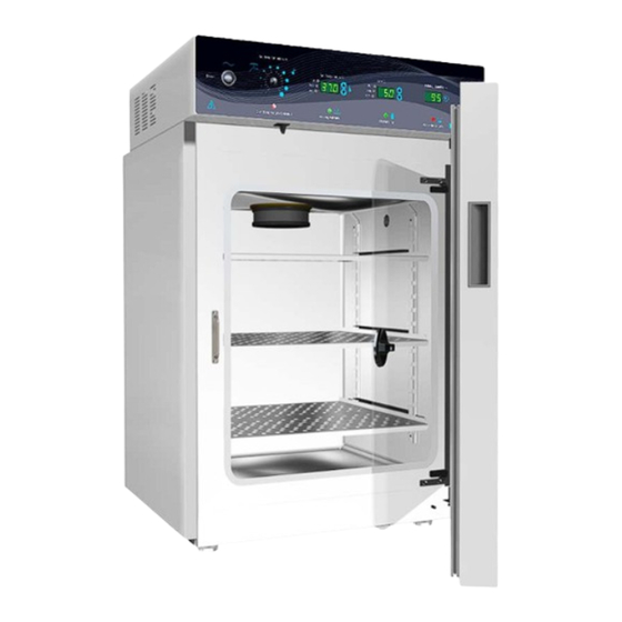
Page 12: Orientation Image
RECEIVING YOUR UNIT RIENTATION MAGE SCO5W Back of Unit Back of Unit Side of Unit Sample Water Jacket Ports Fuse in Power Inlet and Data Ports Fill Siphon Anode In Ports Access Port Chamber Door Handle Control Panel Door Gasket... -
Page 13: Recording Data Plate Information
RECEIVING YOUR UNIT ECORDING LATE NFORMATION The data plate contains the incubator model number and serial number. Tech Support will need this information during any support call. Record it below for future reference. The data plate is located on the inside of the chamber door, top-right corner. •... - Page 14 RECEIVING YOUR UNIT 14 | P a g e...
-
Page 15: Installation
INSTALLATION NSTALLATION HECKLIST Carry out the steps and procedures listed below to install the unit in a new workspace location and prepare it for use. All procedures are found in the Installation section of this manual. Pre-Installation Check that the required ambient conditions and ventilation spacing for the incubator are met, page 16 Unit dimensions may be found on page 57 •... -
Page 16: Required Ambient Conditions
INSTALLATION EQUIRED MBIENT ONDITIONS These units are intended for use indoors, at room temperatures between 15°C and 30°C (59°F and 86°F), at no greater than 80% Relative Humidity (at 25°C / 77°F). Operating outside these conditions may adversely affect its incubator temperature stability and effective operating range. EQUIRED LEARANCES These clearances are required to provide air flows sufficient for ventilation and cooling. -
Page 17: Power Source Requirements
INSTALLATION OWER OURCE EQUIREMENTS When selecting a location for the unit, verify each of the following requirements is satisfied. Power Source The power source for the unit must match the voltage and match or exceed the amperage requirements listed on the unit data plate. These units are intended for 110 - 120V 50/60 Hz applications at 5 Amps Supplied voltage must not vary more than 10% from the data plate rating. -
Page 18: Lifting And Handling
INSTALLATION IFTING AND ANDLING The unit is heavy. Use appropriate lifting devices that are sufficiently rated for these loads. Follow these guidelines when lifting the unit. Lift the unit only from its bottom surface. • Doors, handles, and knobs are not adequate for lifting or stabilization. •... -
Page 19: Install The Incubator
INSTALLATION NSTALL THE NCUBATOR Install the unit in a workspace location that meets the criteria discussed in the previous entries of the Installation section. EIONIZED AND ISTILLED ATER Do not use deionized water to clean or humidify the incubator or fill the water jacket. Use of deionized water may corrode metal surfaces and voids the warranty. -
Page 20: Install Chamber Hepa Filter And Ceiling Air Duct
INSTALLATION HEPA F NSTALL HAMBER ILTER AND EILING The incubator must be unplugged while carrying out this procedure. Exercise caution when installing the ceiling air duct. A plastic blower fan and the fragile head of the temperature and CO sensors are located just above the duct and just to the right of the duct. Step 1 Ceiling Duct Step 2... -
Page 21: Shelving Installation
INSTALLATION HELVING NSTALLATION Install the shelving and humidification pan in the in the incubation chamber. Install the shelf standard rails. • Align the keyhole slot of the standard with the mounting peg on the side of the chamber wall. • Mount the shelf standard. Install the shelf slides. - Page 22 INSTALLATION ONNECT TO THE UPPLY Note: See page 9 for CO supply requirements. to Chamber Optional Tubing Kit with Inline HEPA Filter Connects to 3/16” (4.76mm) ID Tubing Single Source Dual Source “IN” “IN” Connect the supply source to the incubator. If connecting a second supply cylinder, do so now.
-
Page 23: Access Port Stopper
INSTALLATION CCESS TOPPER Each incubator ships with a rubber stopper installed in the access port located on the right side the incubation chamber interior. The stopper should always be installed inside the chamber to obtain the • best temperature uniformity and prevent condensation from forming inside the port. - Page 24 INSTALLATION 24 | P a g e...
-
Page 25: Graphic Symbols
GRAPHIC SYMBOLS Each incubator is provided with multiple graphic symbols on its exterior and internal surfaces. These symbols identify hazards, and the functions of the adjustable components, as well as important notes in the user manual. Symbol Definition Consult the user manual. Consulter le manuel d'utilisation Temperature display Indique l'affichage de la température... - Page 26 GRAPHIC SYMBOLS Symbol Definition Potential shock hazard Risque de choc électrique Indicates the unit should be recycled (Not disposed of in land-fill) Indique l’appareil doit être recyclé (Ne pas jeter dans une décharge) Indicates relative humidity Indique humidité relative Indicates water level low Indique faible niveau d'eau Indicates CO Indique gaz CO...
-
Page 27: Control Panel Overview
CONTROL PANEL OVERVIEW Control Panel Power Switch Power is supplied when the switch is in the ( I ) on position. Set Over Temperature This graduated dial sets the Over Temperature Limit system heating cut off point. The OTL system helps prevents unchecked heating of the incubation chamber in the event the main temperature control system fails. - Page 28 CONTROL PANEL OVERVIEW Display Labeled Set CO this display shows the concentration of CO as a percentage of the incubation chamber atmosphere. The display has a range of OFF (0%) to 20% and an accuracy of 0.1%. The display shows “LO” until the CO sensor registers a concentration in the chamber greater than 0%.
-
Page 29: Operation
OPERATION HEORY OF PERATION SCO5W incubators are engineered to provide a constant temperature CO incubation environment that is passively humidified to prevent the premature drying of sample media. Filling the humidification pan will result in a relative humidity (RH) of 90 – 95% in the chamber. Each incubator... - Page 30 OPERATION Atmosphere The microprocessor also controls the gas concentration of CO in the chamber atmosphere by operating an internal injection solenoid valve connected to a gas input port. The processor monitors concentration level in the incubator using an infrared sensor located in the recirculation duct. The sensor operates on the principle that a specific frequency set of infrared light is absorbed by .
-
Page 31: Put The Incubator Into Operation
OPERATION From a cold start, the incubator requires 12 hours to come up to and stabilize at temperature Note: and humidity levels prior to loading samples. Stabilization safeguards samples. UT THE NCUBATOR INTO PERATION Carry out the following steps and procedures to put the unit into operation after installing it in a new workspace environment. - Page 32 OPERATION Put the Incubator into Operation (Continued) Allow the unit to run 12 hours prior to heat soak to achieve a stable temperature. The manufacturer recommends allowing the unit to • run overnight. Set the Over Temperature Limit. See page 39. The incubator must be heated and stable at your application temperature prior to performing this procedure.
-
Page 33: Humidify The Incubator
OPERATION UMIDIFY THE NCUBATOR The humidification pan must be filled with water in order for the incubator to achieve its stated temperature uniformity specification. Humidifying the chamber helps slow the drying of samples in open, “breathable” containers. Always place and secure the copper token in the pan to slow the growth of microbiological •... - Page 34 OPERATION ET THE EMPERATURE OINT . Set OTL control to its maximum setting, if not already set to max. Turning the OTL all the way to the right (clockwise) prevents the heating cutoff system from interfering with this procedure. Navigate to the Temperature Set Point Adjustment mode Set Temperature ⁰C Set Temperature ⁰C Set Point Adjustment Mode...
-
Page 35: Muting The Audible Temperature Alarm
OPERATION UTING THE UDIBLE EMPERATURE LARM Audible and visual deviation alarms activate if the incubation chamber temperature deviates by 1°C above or below the temperature set point. The low deviation audible alarm has a delay of 15 minutes to prevent the low audible from sounding each time the doors are opened, causing a short-lived drop in temperature. -
Page 36: Start A Flow Of Co
OPERATION TART A LOW OF Gas Cylinder(s) Open the cylinder valve to supply CO to the regulator. Set cylinder regulator flow setting. Single source: Set the regulator to deliver 15 - 20 Pounds per Square Inch (psi) to • the incubator CO in Port. - Page 37 OPERATION ET THE OINT The incubator comes from the factory with the CO set point set to Off. Set the set point percentage to the gas concentration required by your study or production protocol. Navigate to the CO Set Point Adjustment mode Set CO Set CO Initial Set Point...
-
Page 38: Muting The Audible Co Alarm
OPERATION UTING THE UDIBLE LARM A visual devation indicator alarm illuminates if the chamber CO level deviates 1% above or below the set point. An audible alarm sounds immediately for a high deviation. The low deviation audible alarm sounds only after the visual low indicator light has been continually illuminated for 15 minutes. This delay prevents the alarm from sounding each time the chamber doors are opened. -
Page 39: Set The Over Temperature Limit
OPERATION Note: Test the OTL system at least once per year for functionality. ET THE EMPERATURE IMIT This procedure sets the OTL heating cutoff point to approximately 1°C above the current incubation chamber temperature. The unit must be operating stabilized at your application temperature for at least 1 hour prior to setting the OTL cutoff system. -
Page 40: Load The Incubator
OPERATION OAD THE NCUBATOR Place items on the shelves inside the incubation chamber as evenly spaced as possible. Proper spacing allows for maximum air circulation and a high degree of temperature uniformity. Leave 1 inch (25mm) between sample containers and the chamber walls. This completes the Put the Incubator into Operation procedure. -
Page 41: Data Output Capabilities
Example logline output: C1=37.0 C3=5.0 C4=95 Optional Jack Ports SCO5W units may be ordered from the factory equipped with a 4 – 20 milliamp analog output board as a special quote (SQ) unit. The analog 4-20 milliamp outputs can be connected to a building management system (BMS) or other data monitoring and capture system through the use of two (2) jack ports on the left side of the incubator. -
Page 42: Condensation And The Dew Point
OPERATION ONDENSATION AND THE OINT Relative humidity inside the incubator chamber should never be allowed to exceed 95%. Exceeding this threshold will likely result in condensation, possible leaks around the incubator, and may cause corrosion damage if allowed to continue for any significant length of time. Condensation takes place whenever the humidity level in the incubator chamber reaches the dew point. -
Page 43: User Maintenance
USER MAINTENANCE Warning: Disconnect the unit from its power supply prior to performing maintenance or services. Avertissement: Débranchez cet appareil de son alimentation électrique avant d'effectuer la maintenance ou les services. LEANING AND ISINFECTING If a hazardous material or substance has spilled in the unit chamber, immediately initiate your site Hazardous Material Spill Containment protocol. -
Page 44: Minimizing Contamination Exposure
USER MAINTENANCE Disinfecting For maximum effectiveness, disinfection procedures are typically performed after cleaning. Keep the following points in mind when disinfecting the unit. Turn off and disconnect the unit to safeguard against electrical hazards. • Disinfect the unit chamber using commercially available disinfectants that are non-corrosive, •... -
Page 45: Gas Lines And Hepa Filters
USER MAINTENANCE HEPA F INES AND ILTERS For the Optional Filtered Tubing Kit The manufacturer recommends replacing in-line gas HEPA filters once per year or “IN” when a filter is noticeably discolored. HEPA filters are directional and must be installed facing in the correct direction. •... -
Page 46: Replace The Chamber Hepa Filter
USER MAINTENANCE HEPA F EPLACE THE HAMBER ILTER Always turn off and unplug the incubator before carrying out this procedure. Replace the filter at least once per year, or when the filter is noticeably discolored. Exercise caution when removing the ceiling air duct. A plastic blower fan and the fragile head of the temperature and CO sensors are located just above the duct and just to the right of the duct. -
Page 47: Calibrate The Temperature Display
USER MAINTENANCE ALIBRATE THE EMPERATURE DISPLAY Note: This procedure requires a temperature reference device. Please see the Reference Sensor Device entry on page 10 for the device requirements. Temperature calibrations are performed to match the incubator temperature display to the actual air temperature inside the incubation chamber. - Page 48 USER MAINTENANCE Temperature Stabilization The incubator air temperature must be stable in order to perform an accurate calibration. Allow the incubator to operate undisturbed with the chamber door shut for at least 12 hours • when first putting the unit into operation in a new environment. To be considered stabilized, the incubator chamber must operate at your calibration •...
- Page 49 USER MAINTENANCE Temperature Calibration Continued Place the display in its temperature calibration mode. a. Press and hold both the UP and DOWN temperature arrow buttons simultaneously for approximately 5 seconds. b. Release the buttons when the temperature display shows the letters “C O”. The display will begin flashing the current temperature display value.
- Page 50 USER MAINTENANCE Temperature Calibration Continued Compare the reference device reading with the chamber temperature display again. Reference Device If the reference device and the chamber temperature • display readings are the same or the difference falls within the range of your protocol, the incubator is now calibrated for temperature.
-
Page 51: Calibrate The Co 2 Display
USER MAINTENANCE ALIBRATE THE ISPLAY Note: This procedure requires a gas reference device. Please see the Reference Sensor Devices entry on page 10 for the device requirements. Gas calibrations are performed to match the incubator CO display to the actual CO concentration inside the incubation chamber. - Page 52 USER MAINTENANCE Gas Stabilization The CO concentration in the incubation chamber must be given time to stabilize in order to perform an accurate calibration. The unit must be thermally stable, having operated at your application temperature for at • least 12 hours prior to starting the gas calibration. After turning on a flow of CO to the chamber and setting the CO set point, allow the...
- Page 53 USER MAINTENANCE Calibration Continued Place the incubator CO display in its calibration mode. a. Press and hold both the UP and DOWN temperature arrow buttons simultaneously for approximately 5 seconds. b. Release the buttons when the temperature display shows the letters “C O”. The display will then begin flashing the current CO display value.
- Page 54 USER MAINTENANCE Calibration Continued Compare the reference device reading with the incubator CO display again. Reference Device If the reference device and the incubator display readings • are the same or the difference falls within the range of your protocol, the incubator is now calibrated for CO -OR- ...
-
Page 55: Anode And Water Quality
USER MAINTENANCE NODE AND ATER UALITY A replaceable metal anode comes installed in a threaded port near the water-jacket fill port on the back of the unit. The anode dissolves when in contact with the mineral salts and dissolved gasses found in tap water. - Page 56 USER MAINTENANCE 56 | P a g e...
-
Page 57: Unit Specifications
UNIT SPECIFICATIONS The SCO5W Incubator is a 110 – 120 volt unit. Please refer to the incubator data plate for individual electrical specifications. Technical data specified applies to units with standard equipment at an ambient temperature of 25°C and a voltage fluctuation of ±10%. The temperatures specified are determined in accordance to factory standard following DIN 12880 respecting the recommended wall clearances of 10% of the height, width, and depth of the inner chamber. -
Page 58: Capacity
± 0.1% Less than 5 minutes EMPERATURE Range Uniformity Stability Ambient +5ºC to 60ºC ± 0.2ºC at 37ºC ± 0.1°C @ 37°C OWER Model AC Voltage Amperage Frequency SCO5W 110 - 120 50/60 Hz 58 | P a g e... -
Page 59: Parts List
PARTS LIST Part Part Number Part Part Number Fuse T10A 250V Anode, Water Jacket 5X20mm 0260500 3300516 Access Port Stopper, Size 6 Gas Line HEPA Filter 2800525 7750514 Humidification Pan Chamber HEPA FILTER 995-00015 2800517 Leveling Foot Chamber HEPA Filter Cap 2700512 6500606 Power Cord 115 volt 15... -
Page 60: Ordering Parts And Consumables
4 or (503) 640-3000. Please have the model number and serial number of the incubator ready, as Tech Support will need this information to match your unit to its correct part. CCESSORIES The following accessories are available for the SCO5W. Cylinder Regulator, Dual Stage For use with a gas supply cylinder (tank). - Page 61 PARTS LIST 61 | P a g e...
- Page 62 P.O. Box 627 Cornelius, OR 97113 support@sheldonmfg.com sheldonmanufacturing.com 1-800-322-4897 (503) 640-3000 FAX: 503 640-1366...
Need help?
Do you have a question about the SCO5W and is the answer not in the manual?
Questions and answers