Table of Contents
Advertisement
Quick Links
Advertisement
Table of Contents

Subscribe to Our Youtube Channel
Related Manuals for Shel lab SMI31-2


Summary of Contents for Shel lab SMI31-2
- Page 1 SMI INCUBATORS 220 – 240 Voltage Installation - Operation Manual SMI31-2 SMI39-2...
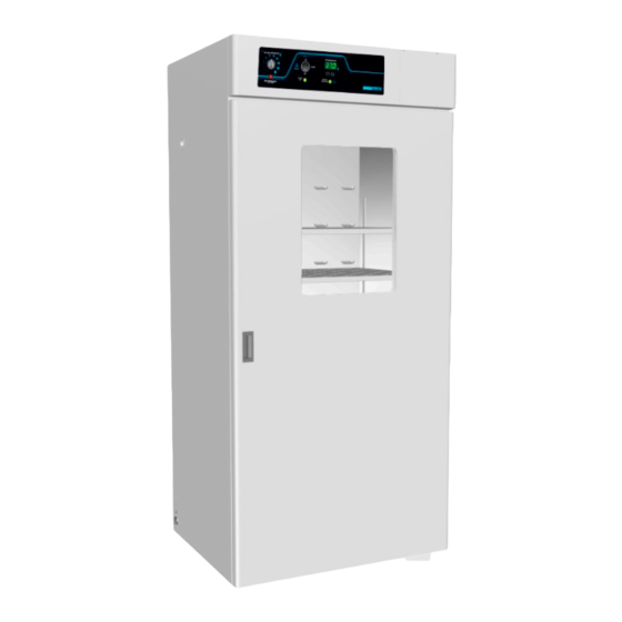
- Page 2 Pictured on Cover: SMI31-2 left, SMI39-2 right These incubators require a 220 – 240-volt power outlet. Warning: This product contains chemicals, including triglycidyl isocyanurate, known to the State of California to cause cancer as well as birth defects or other reproductive harm. For more information, go to www.P65Warnings.ca.gov.
- Page 3 220 – 240 Voltage Part Number (Manual): 4861764 Revised: November 5, 2019 SHEL LAB is a brand of Sheldon Manufacturing, INC, an ISO 9001 certified manufacturer. Safety Certifications These units are CUE listed by TÜV SÜD as incubators for professional, industrial, or educational use where the preparation or testing of materials is done at an ambient air pressure range of 22.14 –...
-
Page 4: Table Of Contents
TABLE OF CONTENTS INTRODUCTION ................................ 5 Read this Manual ..................................5 Safety Considerations and Requirements ........................5 Contacting Assistance ................................6 Manufacturing Warranty ..............................6 Engineering Improvements..............................6 Reference Sensor Device ..............................7 RECEIVING YOUR UNIT ............................9 Inspect the Shipment ................................9 Orientation Images ................................ -
Page 5: Introduction
INTRODUCTION Thank you for purchasing a SHEL LAB incubator. We know you have many choices in today’s competitive marketplace when it comes to constant temperature equipment. We appreciate you choosing ours. We stand behind our products and will be here for you if you need us. -
Page 6: Contacting Assistance
Therefore, some changes, modifications, and improvements may not be covered in this manual. If your unit’s operating characteristics or appearance differs from those described in this manual, please contact your SHEL LAB dealer or customer service representative for assistance. -
Page 7: Reference Sensor Device
INTRODUCTION EFERENCE ENSOR EVICE Must be purchased separately A reference sensor device is required for calibrating the unit temperature display. Reference devices must meet the following standards: Accurate to at least 0.1°C • Temperature The device should be regularly calibrated, preferably by a third party. Reference Temperature Probes Use a digital device with wire thermocouple probes that can be introduced into the unit chamber... - Page 8 INTRODUCTION P a g e...
-
Page 9: Receiving Your Unit
5. The unit should come with an Installation and Operation Manual. 6. Verify that the correct number of accessory items has been included. Carefully check all packaging for accessories before discarding. Included Accessories Model Shelves Shelf Clips Leveling Feet Power Cord SMI31-2 SMI39-2 Shelves SMI31-2 SMI39-2 P a g e... -
Page 10: Orientation Images
RECEIVING RIENTATION MAGES SMI31-2 Control Panel Access Port Chamber Door Chamber Outlet OTL Probe (Top) Temperature Probe (Bottom) Shelf Standard Rail Incubation Chamber Roller Bottle Apparatus Wheel Groove Door Gasket 10 | P a g e... - Page 11 RECEIVING SMI39-2 Control Panel Access Port Chamber Door Chamber Outlet OTL Probe (Top) Temperature Probe (Bottom) Shelf Standard Rail Incubation Chamber Roller Bottle Apparatus Wheel Groove Door Gasket 11 | P a g e...
- Page 12 RECEIVING Power Panel, Left Side of Units Second Fuse Holder Power Cord Inlet with Fuse Holder 12 | P a g e...
-
Page 13: Recording Data Plate Information
RECEIVING ECORDING LATE NFORMATION Record the unit model number, serial number, and part number below for future reference. Tech Support needs this information to provide accurate help during support calls and emails. • The data plate is located on the lower, left side of the unit, above the power inlet. MODEL NO: SERIAL NO: PART NO:... - Page 14 RECEIVING 14 | P a g e...
-
Page 15: Installation
INSTALLATION NSTALLATION ROCEDURE HECKLIST For installing the unit in a new workspace location. Pre-Installation Check that the required ambient conditions for the unit are met, page 16. Check that the spacing clearance requirements are met, page 16. Unit dimensions may be found on page 39. •... -
Page 16: Required Ambient Conditions
4” (102 mm) Door Swing Power Cord SMI31-2 36.0” (914 mm) SMI39-2 42.3” (1075 mm) 4 inches (102 mm) of clearance is required on the sides and back. 2 inches (51 mm) of headspace clearance is required between the top of the unit and any overhead partitions. -
Page 17: Power Source Requirements
Amperage Model Amperage Standard 8.0 Amps 8.5 Amps SMI31-2 SMI39-2 CEE7/7 wall socket The wall power source must be protective earth grounded and single phase. • The unit may be damaged if the supplied voltage varies by more than 10% from the data •... -
Page 18: Lifting And Handling
INSTALLATION IFTING AND ANDLING The unit is heavy. Use appropriate lifting devices that are sufficiently rated for these loads. Follow these guidelines when lifting the unit. Lift the unit only from its bottom surface. • Doors, handles, and knobs are not adequate for lifting or stabilization. •... -
Page 19: Install The Incubator
INSTALLATION NSTALL THE NCUBATOR Install the unit in a workspace location that meets the criteria discussed in the previous entries of the Installation chapter. EIONIZED AND ISTILLED ATER Do not use deionized water to clean the unit, even if DI water is readily available in your laboratory. Use of deionized water may corrode metal surfaces and voids the manufacturing warranty. -
Page 20: Shelving Installation
INSTALLATION HELVING NSTALLATION Install 4 Shelf Clips Rocking Motion Place the Shelf 1. Install the 4 shelf clips in the slots of the shelf standard mounting rails located on the sides of the chamber interior. a. Squeeze each clip, insert the top tab first, and then the bottom tab using a rocking motion. -
Page 21: Graphic Symbols
GRAPHIC SYMBOLS The unit is provided with multiple graphic symbols on its exterior. These identify hazards and adjustable components as well as important notes in the user manual. Symbol Definition Consult the user manual Consulter le manuel d'utilisation Temperature Display Indique l'affichage de la température Over Temperature Limit system Thermostat température limite contrôle haute... - Page 22 SYMBOLS 22 | P a g e...
-
Page 23: Controls Overview
CONTROLS OVERVIEW Control Panel Over Temperature Limit System (OTL) This graduated dial sets the mechanical heating cut off point for the Over Temperature Limit system. The system prevents unchecked heating of the chamber in the event of an electronics failure or external heat spike. - Page 24 CONTROLS 24 | P a g e...
-
Page 25: Operation
OPERATION HEORY OF PERATION Heating When powered, the incubator heats to and maintains a user-selected target setpoint in the incubation chamber. The incubator senses the chamber air temperature using a solid-state probe mounted on the chamber interior wall. When the incubator detects that the chamber temperature has dropped below the target setpoint, it pulses power to the heating element inside the chamber heating duct in the chamber ceiling. -
Page 26: Put The Incubator Into Operation
OPERATION UT THE NCUBATOR INTO PERATION Perform the following steps and procedures to put the unit into operation after installing it in a new workspace environment. Plug in the power cord Attach the power cord that came with the unit to the inlet receptacle on the left side of the incubator. -
Page 27: Set The Temperature Setpoint
OPERATION ET THE EMPERATURE ETPOINT Perform the steps below to adjust the setpoint to your process or application temperature. Set the Over Temperature Limit control to its maximum setting, if not already set to max. This prevents the heating cutoff system from •... -
Page 28: Set The Over Temperature Limit (Otl)
OPERATION Note: Test the OTL system at least once per year to verify its functionality. Failure to set the OTL voids the manufacturing defect warranty if over temperature damage occurs. (OTL) ET THE EMPERATURE IMIT This procedure sets the mechanical heating cutoff to approximately 1˚C above the current chamber temperature. -
Page 29: Loading Samples
OPERATION OADING AMPLES The manufacturer strongly recommends waiting at least 8 hours after putting the incubator in operation before loading samples in the chamber. This safeguards against temperature instability. • Samples should be placed at least 1 inch (25 mm) away from the chamber walls. •... -
Page 30: Condensation And The Dew Point
OPERATION ONDENSATION AND THE OINT Relative humidity inside the incubation chamber should never be allowed to exceed 80% at 25°C. Exceeding this threshold will likely result in condensation or possible leaks around the incubator, and may cause corrosion damage if allowed to continue for any significant length of time. Condensation takes place whenever the humidity level in the incubation chamber reaches the dew point. -
Page 31: User Maintenance
USER MAINTENANCE Warning: Disconnect this unit from its power supply prior to performing maintenance or services. Avertissement: Débranchez cet appareil de son alimentation électrique avant d'effectuer la maintenance ou les services. LEANING AND ISINFECTING If a hazardous material or substance has spilled in the unit chamber, immediately initiate your site Hazardous Material Spill Containment protocol. -
Page 32: Minimizing Contamination Exposure
MAINTENANCE Disinfecting When disinfecting the unit, keep the following in mind: Always turn off and disconnect the unit to safeguard against electrical hazards. • For maximum effectiveness, disinfection procedures are typically performed after cleaning. • Disinfect the unit chamber using commercially available disinfectants that are non-corrosive, •... -
Page 33: Door Components
MAINTENANCE OMPONENTS Periodically, inspect the door latch, trim, catch, and gasket for signs of deterioration. Failure to maintain the integrity of the door system shortens the life span of the unit. LECTRICAL OMPONENTS Electrical components do not require maintenance. If the incubator fails to operate as specified, please contact your distributor or Technical Support for assistance. -
Page 34: Calibrate The Temperature Display
MAINTENANCE ALIBRATE THE EMPERATURE ISPLAY Note: Performing a temperature display calibration requires a temperature reference device. Please see the Reference Sensor Device entry on page 7 for the device requirements. Temperature calibrations are performed to match an incubator temperature display to the actual air temperature inside the incubation chamber. - Page 35 MAINTENANCE 5. The unit temperature must be stable in order to perform an accurate calibration. The incubator must run for at least 8 hours prior to conducting a calibration. • The temperature is considered stabilized when the incubator has operated with the •...
- Page 36 MAINTENANCE Temperature Calibration Continued Place the display in temperature calibration mode. a. Press and hold both the Up and Down temperature arrow buttons simultaneously for approximately 5 seconds. b. Release the buttons when the temperature display shows the letters “C O”. The display will begin flashing the current temperature display value.
- Page 37 MAINTENANCE Temperature Calibration Continued Reference Device Compare the reference device reading with the chamber temperature display. If the reference device and the chamber temperature • display readings are the same or the difference falls within the range of your protocol, the incubator is now calibrated for temperature.
- Page 38 MAINTENANCE 38 | P a g e...
-
Page 39: Unit Specifications
All indications are average values, typical for units produced in the series. We reserve the right to alter technical specifications at all times. EIGHT Model Shipping SMI31-2 570 lb / 259 kg 406.0 lb / 184.0 kg SMI39-2 657 lb / 298 kg 497.0 lb / 225.0 kg... -
Page 40: Chamber Volume
SPECIFICATIONS HAMBER OLUME Model Cubic Feet Liters 30.9 874.0 SMI31-2 38.6 1093.0 SMI39-2 HELF APACITY Model Maximum Weight per Shelf* Max Total Weight** 75.0 lb / 34.0 kg 450.0 lb / 204.0 kg SMI31-2 75.0 lb / 34.0 kg 450.0 lb / 204.0 kg SMI39-2 *With weight distributed evenly across the shelf. -
Page 41: Parts List
Accessories and replacement parts can be ordered online at parts.sheldonmfg.com. If the required item is not listed online, or if you require assistance in determining which part or accessory you need contact SHEL LAB by emailing parts@sheldonmfg.com or by calling 1-800-322- 4897 ext. 4 or (503) 640-3000 ext. 4. - Page 42 P.O. Box 627 Cornelius, OR 97113 support@sheldonmfg.com sheldonmanufacturing.com 1-800-322-4897 (503) 640-3000 FAX: 503 640-1366...
Need help?
Do you have a question about the SMI31-2 and is the answer not in the manual?
Questions and answers