Advertisement
Quick Links
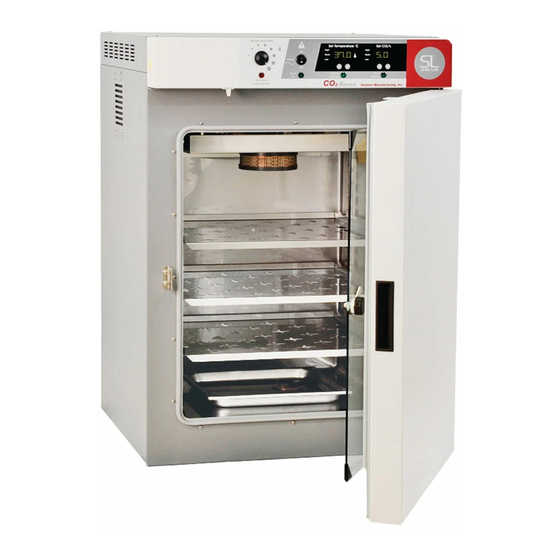
AIR JACKETED CO
2
INCUBATORS
M
: 5215 & 5230
ODELS
I
O
M
NSTALLATION AND
PERATION
ANUAL
REV. 08/11
4861507-1
Sheldon Manufacturing Inc. P.O. Box 627 Cornelius, Oregon 97113
EMAIL:
tech@Shellab.com
INTERNET:
http://www.Shellab.com/~Shellab
1-800-322-4897
(503) 640-3000
FAX (503) 640-1366
Advertisement

Related Manuals for Shel lab 5215


Summary of Contents for Shel lab 5215
- Page 1 AIR JACKETED CO INCUBATORS : 5215 & 5230 ODELS NSTALLATION AND PERATION ANUAL REV. 08/11 4861507-1 Sheldon Manufacturing Inc. P.O. Box 627 Cornelius, Oregon 97113 EMAIL: tech@Shellab.com INTERNET: http://www.Shellab.com/~Shellab 1-800-322-4897 (503) 640-3000 FAX (503) 640-1366...
- Page 2 TABLE OF CONTENTS SECTION 1.0 RECEIVING AND INSPECTION SECTION 2.0 INSTALLATION SECTION 3.0 GRAPHIC SYMBOL SECTION 4.0 CONTROLS OVERVIEW SECTION 5.0 OPERATION SECTION 6.0 CALABRATION AND READING A FYRITE SECTION 7.0 MAINTENANCE SECTION 8.0 HEPA C02 FILTER SECTION 8.0 TROUBLESHOOTING SECTION 9.0 PARTS LIST UNIT SPECIFICATIONS...
- Page 3 Customer Service. Accessories: Verify that your accessory kit is complete. The 5215 is equipped with 3 shelves, supply hose kit, 4 leveling feet and pan. The 5230 is equipped with 6 shelves, supply hose kit, 4...
- Page 4 Section INSTALLATION Local city, county, or other ordinances may govern the use of this equipment. If you have any questions about local requirements, please contact the appropriate local agency. Installation may be performed by the end user. Under normal circumstances this unit is intended for use indoors, at room temperatures between 5 and 35C, at no greater than 80% Relative Humidity (at 25) and with a supply voltage that does not vary by more than 10%.
- Page 5 Assure all volatile or flammable cleaners are evaporated and dry before reconnecting the unit to the power supply. B. Special care should be taken when cleaning around sensing heads to Prevent damage. (See figure 1) Figure 1 C. Do not use chlorine-based bleaches or abrasive cleaners. These will modify the stainless steel interior finish.
- Page 6 Place shelves in chamber as desired.
- Page 7 Section GRAPHIC SYMBOLS Your CO incubator is provided with a display of graphic symbols on the control panel, which are designed to help identify the use and function of the adjustable components. Indicates that you should consult your manual for further description and discussion of a control or user item.
- Page 8 Section CONTROL PANEL OVERVIEW (See Figure 1) Figure 1 All controls are located on the front panel. Units with a detachable cord have a fused inlet located at the top rear of the incubator. This inlet has a recessed male plug, fuse and an EMI filtering system designed to filter out electrical interference.
- Page 9 Section OPERATION Check power supply against unit serial plate; they must match. Be certain that the fuse is installed in the power inlet of the unit. Plug service cord into the electrical outlet. Push power switch to the ON position, and turn the High Limit Thermostat to its maximum position, clockwise.
- Page 10 should be changed and the pan cleaned at least once a week to help control contamination and to maintain proper surface tension. Supply System and Control System: The CO system is rated for input pressures between 5 to 40 PSI which should never be exceeded at any time Humidity Pan PLUMBING DIAGRAM (figure 2) The CO...
- Page 11 The micro processor CO control system interprets the information from the CO sensor, displays the concentration directly on the digital display, reads the CO set point and controls the percentage of CO in the incubator chamber. The CO sensors operate under the principal that a certain frequency of infrared light is absorbed by .
- Page 12 Section FYRITE CO CHECKING A Bacharach FYRITE CO Gas Analyzer is recommended to measure CO concentrations in the incubator chamber. This test instrument is not supplied with the incubator but is readily available from your dealer. Follow the instructions provided with each Fyrite instrument carefully to insure correct and accurate readings.
- Page 13 Section MAINTENANCE NOTE: Prior to any maintenance or service on the unit, disconnect service cord from the power supply. Cleaning: Disinfect the incubator interior on a regular basis. To prepare the incubator for cleaning remove the shelves and shelf slides. These stainless steel parts are autoclavable. First clean removed parts and interior with soap and water.
- Page 14 Section HEPA CO FILTER The CO Incubator design features a HEPA filtration system with a patented copper housing. (Patent Number 6,333,004) As the chamber air is drawn through the filter system, airborne microbes and isolated particulates are not only removed from the air, but destroyed as well.
- Page 15 Section TROUBLESHOOTING Always make a visual inspection of the incubator and control console when troubleshooting. Look for loose or disconnected wires or tubing which may be the source of the problem. The incubator is designed so that no internal electrical servicing should be required under normal conditions.
- Page 16 Overshoots set point and continues to rise - display and Fyrite match Debris in solenoid causing it to leak continuously Rises very slowly 1/ Filter overly dirty or partially plugged 2/ Hose kinked or leaking 3/ CO tank regulator set too low. 4/ CO tank near empty Never rises...
- Page 17 1/ Make sure that the fan or blower wheel is not contacting its housing. Adjust the motor mounting bracket position to re-center the fan or blower wheel, if necessary. 2/ Check the fan or blower wheel for damage or out of balance condition. Replace the fan or blower wheel if it is damaged or out of balance.
- Page 18 Section PARTS LIST Description 115V 220V 4 TO 20mA BOARD 1750667 1750667 Chamber Gasket, 8 feet 3450546 3450546 Circulating Fan 4880564 4880563 Display Board 1750660 1750660 Fan Motor 4880508 4880507 Filter 2800525 2800525 Door Heater 2350550 2350550 Door Switch 7850578 7850578 Element 9570902...
- Page 19 UNIT SPECIFICATIONS Weight Shipping 5215 5215-2 5230 5230-2 Dimensions Exterior WxDxH (in.) Interior WxDxH (in.) 5215 26.75 X 27 X 38 20.5 X 20 X 23.25 5215-2 26.75 X 27 X 38 20.5 X 20 X 23.25 5230 26.75 X 27 X 76 20.5 X 20 X 23.25...
- Page 20 WIRE DIAGRAM IEC FUSED FILTERED INLET 104179 115V - 10A - 3300516 230V - 6.3A - 3300515 115V - NOT USED 230V - 6.3A - 3300515 MAIN POWER SWITCH 7850532 115V - 210002 230V - 210001 JACKET 115V - 100909 CO2 HEATER - 6W 230V - 103328 200021...
- Page 21 SHELDON MANUFACTURING, INC. LIMITED WARRANTY Sheldon Manufacturing, Inc., (“Manufacturer”) warrants for the original user of this product in the U.S.A. only that this product (parts only if outside of the U.S.A.) will be free from defects in material and workmanship for a period of one year from the date of delivery of this product to the original user (the “Warranty Period”).
Need help?
Do you have a question about the 5215 and is the answer not in the manual?
Questions and answers