Table of Contents
Advertisement
Quick Links
Advertisement
Table of Contents

Related Manuals for Amico Alarm Valve Combo Unit


Summary of Contents for Amico Alarm Valve Combo Unit
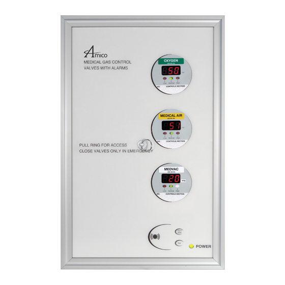
- Page 1 Installation and Maintenance Manual Alarm Valve Combo Unit Alert-1 v1.6...
-
Page 2: Table Of Contents
Installation of Alarm 9-10 Local Sensor Only Standing Pressure Test Frame/Module Assembly Sensor Local Remote Wiring System Power Supply Annunciator Module Sensor Module Local Remote Annunciator Module Noise Level Control Control of Remote Alarm Buzzer The Display Module 13-16 Amico Corporation... - Page 3 Appendix C - Wiring Diagram - Alarm Valve Combo Unit Appendix D - Wiring Diagram - Remote Alarm Valve Combo Unit Appendix E - Wiring Diagram - Alarm Valve Combo Unit to Master Module Appendix F - Technical Specifications Wiring...
-
Page 4: User Responsibility
The Alarm Valve Combo Unit must be checked periodically. Parts that are broken, missing, worn, distorted or contaminated must be replaced immediately. Should such repair or replacement become necessary, please contact Amico Corporation or their distributors. -
Page 5: Introduction
Introduction The Alarm Valve Combo Unit is a 2 in 1 design, which combines the Area Alarm and Zone Valve Box, to compensate for space restrictions. Amico Shutoff Valves are used to stop the flow of medical gas or vacuum in the medical gas distribution pipeline in cases of emergency or maintenance. -
Page 6: Installation Of Valve Boxes
Installation of Alarm Valve Combo Unit Boxes The Amico Valve Combo Unit is shipped in one container holding two separate packages. One package contains the Alarm Valve Combo. The other package contains the window and the frame assembly. 1. Recessed Valve Box: anchor the valve box rough-in to the studs so that the front edge will be flush or slightly recessed with the finished wall. -
Page 7: Maintenance And Annual Test
Authorized hospital personnel should close shutoff valves in the event of fire, explosion or damage to the pipeline systems or equipment. In Alarm Valve Combo Unit boxes, the Shutoff Valve handles become accessible after the window has been removed from the valve box. -
Page 8: Description Of Modules
This module also contains a fail-safe relay that de-energizes when the buzzer is activated. This relay can be used with the Amico remote buzzer, for applications requiring a remote audible alarm (see Appendix B), for connection to another Amico alarm or a building management system. -
Page 9: Installation Of Alarm
Frame/Module Assembly Step #1 Remove the frame/valve window from its protective box Step #2 Attach the Sensor wire to the display module (Sensor +, -) Step #3 Close the valve window www.amico.com... -
Page 10: Sensor
With a wrench, tighten the nut so that it makes a sensor module hex-nut and nipple adapter up into the demand good seal. check-valve. With a wrench, tighten the nut so that it makes a Amico Corporation good seal. -
Page 11: Wiring
PLEASE NOTE: When remote sensors are used, a #22 gauge stranded, shielded twisted pair cable is required (BELDEN #8451 or equivalent, supplied by others). Ensure that the proper gas sensor module is connected to its corresponding area display module, otherwise an error message (E02) will be displayed on the Display module. www.amico.com... -
Page 12: Annunciator Module
6. Set switches #5 and #6 the OFF position 7. Turn on #10 if AIMS is connected (do not turn on #8) When you have completed step #7, the display module will automatically go into “RESET” mode. This will store the data that you entered. Amico Corporation... -
Page 13: The Display Module
[(Display dd=Disabled) Range from 1 to 60 Minutes] 7. Set switch #6 to the OFF position. When you have completed step #7, the display module will automatically go into “RESET” mode. This will store the data “UP” and “DOWN” that you entered. Push Button www.amico.com... -
Page 14: Psi/Kpa/Bar Selection
[(Display dd=Disabled) Range from 1 to 60 Minutes]. 7. Set switch #6 to the OFF position. When you have completed step #7, the display module will automatically go into “RESET” mode. This will store the data that you entered. Amico Corporation... -
Page 15: Inchhg/Kpa/Bar Selections
• No Repeat alarm, but set for 30 min. 1. Set switch #8 to the ON position. 2. Turn the power off (wait 5 seconds) then back on. 3. Set switch #8 to the OFF position. The module is now in the default mode. www.amico.com... -
Page 16: Setting Gas Identification Switches
#1 - on #1 - on #1 - off #2 - off #2 - on #2 - on #2 - off #3 - off #3 - on #3 - off #3 - off P a g e : 2 1 Amico Corporation... -
Page 17: Troubleshooting Guide
Ensure that the DC power plug is firmly in its annunciator module socket on the annunciator module. Replace System Power Supply unit if all the above steps fail to resolve the problem. Defective ribbon cable Replace the ribbon cable www.amico.com... - Page 18 12 inHg High Pressure: Hi: Nitrogen & Air 195 Psi Low: Nitrogen & Air 140 Psi If calibration is required, refer to setting HIGH and LOW calibration procedure on page 13-14 Faulty display module Replace the display module. Amico Corporation...
-
Page 19: Error Code Messages On The Display Module
Reverse polarity or replace cable if defective 26/27 shorted out or reversed polarity Out of calibration / Sensor not reading gas Replace the sensor module 26/27 NOTE: Any of other error codes, contact Amico technical support to isolate the issue www.amico.com... -
Page 20: Model Numbers
Model Numbers Alarm Valve Combo Unit AVL-XGXGXGXGXGXGXG The ”L” Defines the Replace ”X” with the Valve Size: The ”G” Defines the Gas: Language: 1 = 1/2" [1.3 cm] O = Oxygen U = English (NFPA) 2 = 3/4" [1.9 cm]... - Page 21 ALARM VALVE COMBO MYLAR ENG. AIR NFPA A2P-AVC-MYLA-U-W ALARM VALVE COMBO MYLAR ENG. WAG NFPA A2X-AVC-RIBBON2 2 STN RIB CABLE FOR ALRM/VALVE COMBO A2X-AVC-RIBBON3 3 STN RIB CABLE FOR ALRM/VALVE COMBO A2X-AVC-RIBBON4 4 STN RIB CABLE FOR ALRM/VALVE COMBO www.amico.com...
-
Page 22: Spare Parts Numbers
DISS DEMAND CHECK VALVE 1/4"MNPT - VAC S-DIS-DEMC-N2O DISS DEMAND CHECK VALVE 1/4"MNPT – N2O S-DIS-DEMC-NIT DISS DEMAND CHECK VALVE 1/4"MNPT - NIT S-DIS-DEMC-CO2 DISS DEMAND CHECK VALVE 1/4"MNPT – CO2 S-DIS-DEMC-EVA DISS DEMAND CHECK VALVE 1/4"MNPT - EVA Amico Corporation... -
Page 23: Dimensions
Dimensions Vertical Alarm Valve Combo Unit Inch [mm] 1.88 [48] Remote Sensor Wrench Flats [25] DISS (approximate, can vary) 1/2" Conduit CONNECTOR Connection 1/2"-14 NPSM [13] (see thread specs.) www.amico.com... -
Page 24: Appendix A - Wiring Diagram - Auto-Switching Power Supply
Fuse (1 AMPw) DC Power Cable: Connect to Annunciator Module CAUTION: Verify that power has been switched off prior to working on the alarm Risk of electric shock, disconnect power at the circuit breaker before removing power supply shield Amico Corporation... -
Page 25: Appendix B - Wiring Diagram - Annunciator
Appendix B Wiring Diagram – Annunciator NOTE: Amico recommends max. 50 ft. to power up buzzer from any Amico devices (alarm/manifold). More than 50 ft., a A3P-Power-V4 is required to supply voltage for the manifold buzzer. www.amico.com... -
Page 26: Appendix C - Wiring Diagram - Alarm Valve Combo Unit
Appendix C Wiring Diagram – Alarm Valve Combo Unit Sensor Module SENSOR REMOTE COM NC NO COM NC NO HIGH ALARM ALARM Black Sensor Module SENSOR REMOTE COM NC NO COM NC NO HIGH ALARM ALARM Sensor Module Black Ground... -
Page 27: Appendix D - Wiring Diagram - Remote Alarm Valve Combo Unit
Appendix D Wiring Diagram – Remote Alarm Valve Combo Unit #22 gauge stranded, shielded twisted pair cable only must be used, up to #22 Gauge twisted 6" - 8" [0.1m - 0.2 m] #22 a distance of 2500 ft [762 m]. In the... -
Page 28: Appendix E - Wiring Diagram - Alarm Valve Combo Unit To Master Module
Appendix E Wiring Diagram - Alarm Valve Combo Unit to Master Module #22 gauge stranded, shielded twisted pair cable only must be used, up to a distance of 2500 ft [762 m]. In the 6" - 8" [0.1m - 0.2 m] #22... -
Page 29: Appendix F - Technical Specifications
For Master Alarm, source equipment signal wires must be connected to normally-closed dry contacts. No electrical voltage can be present and contacts must be closed during normal equipment operation. When contacts are open; an alarm condition will be activated. www.amico.com... -
Page 30: Wiring
The following rules along with references to this manual’s schematics clarify wiring requirements. Two conductor cables (must be #22 gauge stranded, shielded and twisted pair cable type) are required for each Gas Sensor module to the Gas Input board. Amico Corporation... - Page 32 Amico Corporation | 85 Fulton Way, Richmond Hill, ON L4B 2N4, Canada 71 East Industry Court, Deer Park, NY 11729, USA US LISTED Toll Free Tel: 1.877.462.6426 | Tel: 905.764.0800 | Fax: 905.764.0862 Email: info@amico.com | www.amico.com APE-MANUAL-ALM-VLV-CMB 08.17.2017...
Need help?
Do you have a question about the Alarm Valve Combo Unit and is the answer not in the manual?
Questions and answers