
Related Manuals for Amico Alert-2


Summary of Contents for Amico Alert-2
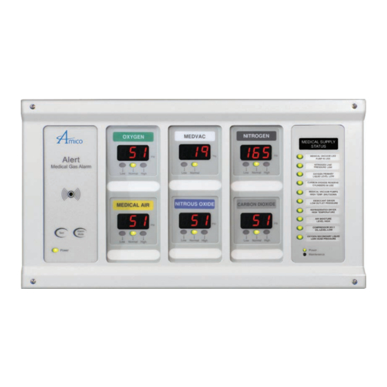
- Page 1 Operating & Maintenance Manual Alert-2 Microprocessor Based Digital Alarm System v5.9 w w w . a m i c o . c o m...
-
Page 2: Table Of Contents
The Alarm Back Box For Local Sensor Only Standing Pressure Test Frame/Module Assembly Sensor Local Remote Wiring 12 - 14 System Power Supply Annuciator Module Sensor Module Local Remote Area Display Module 2 in 1 Display Module Amico Pipeline Amico Pipeline... - Page 3 22 - 24 Error Code Messages on the Display Module Model Numbers 25 - 28 Area Alarm Master Alarm Compact Alarm NEMA 4 Alarm Compact Master Combination Alarm 2 in 1 Area Alarm Spare Part Numbers 29 - 31 www.amico.com...
- Page 4 Appendix M - Wiring Diagram: Pressure Switch Connection to a Master Alarm Appendix N - Wiring Diagram: Computer Interface Module Appendix O - Wiring Diagram: Master to Slave Module Appendix P - Technical Speci cation Notes 54 - 55 Amico Pipeline...
-
Page 5: User Responsibility
Amico Corporation or their distributors. All alarms should not be repaired, or altered without prior written or verbal approval of Amico Corporation or its distributors. All alarms should not be repaired, or altered without prior written or verbal Failure to comply will void all warranty on the alarm. - Page 6 The Alert-2 microprocessor based digital alarm system complies with NFPA-99. The Alert-2 microprocessor based digital alarm system is UL Listed to U.S. and Canadian safety standards. FEATURES Individual Microprocessor on each display, sensor and master module. Gas speci c sensors can be mounted locally or remote, up to 2,500 feet, [750m] utilizing 22 gauge twisted pair (shielded cable should be used).
-
Page 7: Description Of The Alarm
Description of the Alarm SHIPMENT DETAILS When you receive an ALERT-2 series alarm from Amico Corporation, the package will consist of two main sections; the Alarm Back Box and the Frame/Module Assembly. The Frame/Module assembly will be pre-con gured, with the appro- priate display modules, based upon the customer’s speci cations. -
Page 8: Annunciator Module
This module also contains a fail-safe relay “A that de-energizes when the buzzer is activated. This relay can be used with the “Amico remote buzzer”, for applications requiring a remote audible alarm (see Appendix B), for connection to another Amico Alarm or a Building Management System. -
Page 9: Compact Display Module
PLEASE NOTE: Contacts located on back of module are Dry Contacts only. DO NOT apply any voltage. For Annual Test • Reset power to make sure all LED’s light up • Push and hold the ‘Test’ button to light up all LED’s and the audible alarm www.amico.com... -
Page 10: Computer Interface Module
Attach the frame wire with 2 dome head screws (provided with frame in plastic bag). Step #5 Close the frame panel and tighten the screws on the frame plate. Step #6 Carefully place the front frame over the fastened plate. Refasten the screws that were removed in Step #2. Amico Pipeline... -
Page 11: Sensor
CAUTION: The microprocessor circuitry on the ALERT-2 alarm con- tains sophisticated integrated semiconductors. If it becomes necessary CAUTION: The microprocessor circuitry on the ALERT-2 alarm contains sophisticated integrated semiconductors. If it to remove a module, PLEASE hold the boards by the edges. DO NOT becomes necessary to remove a module, PLEASE hold the boards by the edges. -
Page 12: Wiring
Wiring or their distributors. All alarms should not be repaired, or altered without prior written or verbal approval of Amico Corporation or it’s distributors. Failure to comply will void SYSTEM POWER SUPPLY all warranty on the alarm. TURN OFF THE POWER SWITCH BEFORE CHANGING ANY MODULES AND/OR DISCONNECTING ANY CABLES, OR ELSE... - Page 13 3. For Version 3 ENSURE that the unused terminals in the master module are jumpered. If this is not done, the terminals that have not been jumpered will go into alarm. For Version 4, turn o switches for any unused points (SW2). www.amico.com...
-
Page 14: Wiring
NORM module is silenced. The buzzer will only silence when alarm condition has been cleared. Please refer to TEST Appendix B. ALRM = Remote alarm will not silence when annunciator Amico Pipeline module is silenced. The buzzer will only silence... -
Page 15: Steps To Re-Calibrate The Sensor From Area Module V4.0
[(Display dd=Disabled) Range from 1 to 60 Minutes] point. Adjust set point using the “UP” and “DOWN” push buttons, Set switch #6 to the OFF position. to the desired value. [(Display dd=Disabled) Range from 1 to 60 Minutes] Set switch #6 to the OFF position. www.amico.com... - Page 16 [(Display dd=Disabled) Range from 1 to 60 Minutes] Set switch #6 to the OFF position. When you have completed step #7, the display module will automatically go into a “RESET” mode. This will store the data that you had entered. Amico Pipeline...
-
Page 17: Common Settings For Pressure And Vacuum
PLEASE NOTE: The Module with the Lowest set Repeat Time is the one that controls the Repeat Time. For example if one Module is set for 5min and one for 30min and both are Repeat Alarm en- abled, the Alarm will now Repeat every 5min. www.amico.com... -
Page 18: Setting Factory Default
The module is now in the default mode. or their distributors. All alarms should not be repaired, or altered without prior written or verbal approval of Amico Corporation or it’s distributors. Failure to comply will void all warranty on the alarm. WARNING... -
Page 19: Master/Nema 4 Status Module
Set switch #1 to the ON position. 24 HR Set switch #2 to the ON position. PLEASE NOTE: The above repeat alarm only applies to the Master/NEMA 4 alarm, for the 2 in 1 please refer to page 17. www.amico.com... -
Page 20: Signal Input Selection
SIGNAL INPUT SELECTION Version Factory Default - Normally Closed as per NFPA 99. The Amico alarm can detect eld devices in the Normally Open or Normally Closed position. For Normally Closed Set switch #3 to the OFF position. For Normally Open Set switch #3 to the ON position. - Page 21 Masterboard. ALL CHANNELS ALL CHANNELS ACTIVATED DEACTIVATED NOTE: Version 3: Jumper any unused points on the Master module Version 4: Jumper any unused points on the Master module. Turn OFF dip-switches for any unused points (Location SW-2) www.amico.com...
-
Page 22: Troubleshooting Guide
1. Ensure that the DC power plug is to the annunciator module. rmly in it’s socket on the annunciator module. 2. Replace System Power Supply unit if all the above steps fail to resolve the problem. d. Defective Ribbon cable. 1. Replace the ribbon cable. Amico Pipeline... - Page 23 1. Ensure that the system was properly LED’s are not illuminating. calibrated. ordered. Factory default settings: Mid Pressure: Hi Pressure 60 Psi Low Pressure 40 Psi Vacuum: Low Vacuum 12 inHg High Pressure: Hi: Nitrogen & Air 195 Psi Low: Nitrogen & Air 140 Psi www.amico.com...
-
Page 24: Error Code Messages On The Display Module
Display Module. Cable between the sensor and display Reverse polarity or replace cable if defective. 41 / 42 module shorted out or reversed polarity. Out of Calibration / Sensor not reading gas Replace the sensor module 41 / 42 Amico Pipeline... -
Page 25: Model Numbers
4 gang back box 7 gang back box 20 functions = 60 functions = A2M-E-20 A2M-E-60 4 gang back box 7 gang back box Example: 2 Modules, English (20 Functions) = A2M-E-20 NOTE: Please specify the gang back box on each alarm. www.amico.com... - Page 26 NEMA 4 ALARM A2MN-L-XX The Letter “L” Represents The Letters “XX” De nes the the Langauge: Number of Functions: E = English (CSA/NFPA) 10 = 10 Functions F = French (CSA) 20 = 20 Functions S = Spanish (NFPA) Amico Pipeline...
-
Page 27: Model Numbers
Type of Gases:: Oxygen R = Remote/Local Sensors Medical Air C = Conversion MedVac Nitrous Oxide Nitrogen Carbon Dioxide U = English (NFPA) WAGD (NFPA) E = English (CSA) F = French (CSA) AGSS (ISO) S = Spanish (NFPA) Instrument Air www.amico.com... - Page 28 MedVac 111111 = 6 Gases The Letter “L” Represents Nitrous Oxide the Langauge: Nitrogen Carbon Dioxide = C U = English (NFPA) WAGD E = English (CSA) AGSS F = French (CSA) Instrument Air S = Spanish (NFPA) Amico Pipeline...
-
Page 29: Spare Part Numbers
A2P-AREA-U-OXY Area alarm module USA - OXY Alert-2 A2P-AREA-U-VAC Area alarm module USA - VAC Alert-2 A2P-AREA-U-WAG Area alarm module USA - WAG Eng. Alert-2 A2P-AREA-CB-AIR Area circuit board assembly - AIR A2P-AREA-CB-CO2 Area circuit board assembly - CO2 A2P-AREA-CB-EVA... - Page 30 Sensor module USA-HEL Eng. Alert-2 A2P-SENS-U-HEO Sensor medule USA-HELIOX Alert-2 A2P-SENS-U-HPA Sensor module HP-AIR Eng. Alert-2 A2P-SENS-U-LAI Sensor module USA LAB AIR Eng. Alert-2 A2P-SENS-U-OXY Sensor module USA-OXY Eng. Alert-2 A2P-SENS-U-VAC Sensor module USA-VAC Eng. Alert-2 A2P-SENS-U-WAG Sensor module USA-WAG Eng. Alert-2...
- Page 31 Compact Board Mylar Top (NFPA) - OXY A2P-MYLCPT-U-VAC Compact Board Mylar Top (NFPA) - VAC A2P-MYLCPT-U-WAG Compact Board Mylar Top (NFPA) - WAG A2P-MYLCPT-U-IAIR Compact Board Mylar Top (NFPA) - IAIR A2P-MYLCP-BLNK Compact Board Mylar - Blank A2P-MYLCP-COVER Compact Board Mylar - Cover www.amico.com...
-
Page 32: Dimensions
From 1 to 4 modules 17 (439) 18 (465) 25 [635] FROM 1 TO 6 MODULES 24 [610] From 1 to 6 modules 24 (610) 25 (635) DISS CONNECTOR (approximate, can vary) 1/2” Conduit Connection 1/2”-14 NPSM [13] (see Thread Specs.) Amico Pipeline... - Page 33 7 (178) 8 (203) From 1 to 2 modules 11 (272) 12 (305) From 1 to 3 modules 14 (356) 15 (381) From 1 to 4 modules 17 (439) 18 (465) From 1 to 6 modules 24 (610) 25 (635) www.amico.com...
- Page 34 From 1 to 3 modules 14 (356) 15 (381) [25] From 1 to 4 modules 17 (439) 18 (465) From 1 to 6 modules 24 (610) 25 (635) DISS CONNECTOR (approximate, can vary) 1/2” Conduit Connection 1/2”-14 NPSM [13] (see Thread Specs.) Amico Pipeline...
- Page 35 From 1 to 3 modules 14 (356) 15 (381) [25] From 1 to 4 modules 17 (439) 18 (465) From 1 to 6 modules 24 (610) 25 (635) DISS CONNECTOR (approximate, can vary) 1/2” Conduit Connection 1/2”-14 NPSM [13] (see Thread Specs.) www.amico.com...
- Page 36 From 1 to 3 modules 14 (356) 15 (381) From 1 to 4 modules 17 (439) 18 (465) DISS From 1 to 6 modules 24 (610) 25 (635) CONNECTOR (approximate, can vary) 1/2” Conduit Connection 1/2”-14 NPSM [13] (see Thread Specs.) Amico Pipeline...
- Page 37 NEMA 4 ALARM Inch [mm] Side View Top View 10.50 [267] 6.125 8.50 [156] [216] Side View Top View 14.55 [370] 8.625 12.55 [219] [319] www.amico.com...
-
Page 38: Appendix A - Wiring Diagram: Auto-Switching Power Supply
Appendix A Wiring Diagram Auto-Switching Power Supply AC Supply L - Live 115 to 220 VAC N - Neutral G - Ground Ground Toggle Switch Fuse (1 AMPw) DC Power Cable: Connect to Annunciator Module Amico Pipeline... -
Page 39: Appendix B - Wiring Diagram: Annunciator
Version 3.1 or newer. Relays are not fail safe for Versions 3.0 or older. NOTE: Relays on the annunciator are fail safe for version 3.1 or newer. Relays are not fail safe for version 3.0 or older. www.amico.com... -
Page 40: Appendix C - Wiring Diagram: Automatic Voice/Pager Dialing System
Version 3.1 or newer. NOTE: Relays are not fail safe for Versions Relays on the annunciator are fail safe for 3.0 or older. version 3.1 or newer. Relays are not fail safe for version 3.0 or older. Amico Pipeline... -
Page 41: Appendix D - Wiring Diagram: Area Display Module (Local Sensor)
Appendix D Wiring Diagram Area Display Module - Local Sensor OXYGEN # 22 Gauge twisted pair shielded cable 6”-8” [0.1m-0.2m] supplied www.amico.com... -
Page 42: Appendix E - Wiring Diagram: Area Display Module (Remote Sensor)
Appendix E Wiring Diagram Area Display Module - Remote Sensor 2,500 750 NOTE: For multiple sensors, a multi-conductor twisted pair, shielded cable should be used. Amico Pipeline... -
Page 43: Appendix F - Wiring Diagram: 2 In 1 Display Module
6”-8” [0.1m-0.2m] supplied Black Source Equipment Dry contacts for remote monitoring of High and Low alarms NO NC COM NO NC COM Dry contacts only, no voltage 2 in 1 Note: Module Jumper any unused points www.amico.com... -
Page 44: Appendix G - Wiring Diagram: Compact Module
Appendix G Wiring Diagram Compact Module 2,500 750 NOTE: Version 3: Jumper any unused points on the Master module Version 4: Jumper any unused points on the Master module. Turn OFF dip-switches for any unused points (Location SW-2) Amico Pipeline... -
Page 45: Appendix H - Wiring Diagram: Area Module To Master Module
Wiring Diagram Area Module to Master Module 2,500 750 NOTE: Version 3: Jumper any unused points on the Master module Version 4: Jumper any unused points on the Master module. Turn OFF dip-switches for any unused points (Location SW-2) www.amico.com... -
Page 46: Appendix I - Wiring Diagram: 2 In 1 Module To Master Module
2 in 1 Module to Master Module 2,500 750 NOTE: Version 3: Jumper any unused points on the Master module Version 4: Jumper any unused points on the Master module. Turn OFF dip-switches for any unused points (Location SW-2) Amico Pipeline... -
Page 47: Appendix J - Wiring Diagram: Abnormal Condition
Appendix J Wiring Diagram Abnormal Condition SW-2 Source Equipment NOTE: Version 3: Jumper any unused points on the Master module Version 4: Jumper any unused points on the Master module. Turn OFF dip-switches for any unused points (Location SW-2) www.amico.com... -
Page 48: Appendix K - Wiring Diagram: Area Slave
- + - + NO NC COM NO NC COM Note: Set the gas specific dip switch on each area slave panel NOTE: “The slave alarm does not work with A2P-POWER-CONV, both Alarm must be attached the A2P-POWER-V2” Amico Pipeline... -
Page 49: Appendix L - Wiring Diagram: Master/Nema 4 Module
Version 3: Jumper any unused points on the Master module Note: Turn OFF dip-switches for any unused points (Location SW-2) Version 4: Jumper any unused points on the Master module. Turn OFF dip-switches for any unused points (Location SW-2) www.amico.com... -
Page 50: Appendix M - Wiring Diagram: Pressure Switch Connection To A Master Alarm
Normally Open - Red Normally Open - Yellow Note: There are 2 NIT switches, one for high alarm and one for low alarm. NOTE: There are 2 NIT switches, one for high alarm and one for low alarm. Amico Pipeline... -
Page 51: Appendix N - Wiring Diagram: Computer Interface Module
Note: Turn OFF dip-switches for any unused points Version 3: Jumper any unused points on (Location SW-2) the Master module Version 4: Jumper any unused points on the Master module. Turn OFF dip-switches for any unused points (Location SW-2) www.amico.com... -
Page 52: Appendix O - Wiring Diagram: Master To Slave Module
Note: Turn OFF dip-switches for any unused points Version 3: Jumper any unused points on (Location SW-2) the Master module Version 4: Jumper any unused points on the Master module. Turn OFF dip-switches for any unused points (Location SW-2) Amico Pipeline... -
Page 53: Appendix P - Technical Speci Cation
Minimum #22 gauge wire (does not have to be shielded, twisted pair). Signal: 5 VDC, < 5 µA. Computer Interface Board: Output: Dry Contacts NC, open on Alarm. Rating: 30 VDC 1.0 Amps. 60 VDC 0.3 Amps. 125 VAC 0.5 Amps. www.amico.com... -
Page 54: Notes
Notes Amico Pipeline... -
Page 55: Notes
Notes www.amico.com... - Page 56 Amico Pipeline | www.amico.com 85 Fulton Way , Richmond Hill Ontario, L , Canada US LISTED Toll Free Tel: 1.877.264.2697 Toll Free Fax: 1.866.440.4986 Tel: 905.764.0800 Fax: 905.764.0862 Email: info@amico.com APE-OPER-MAINT-ALM-V5.8 04.23.2014...
Need help?
Do you have a question about the Alert-2 and is the answer not in the manual?
Questions and answers