
Related Manuals for Amico ALERT-1


Summary of Contents for Amico ALERT-1
- Page 1 ACorporation ALERT-1 M I C O DIGITAL ALARM & SURVEILLANCE SYSTEMS FOR THE HEALTH CARE INDUSTRY INSTALLATION & MAINTENANCE M A N U A L S U I TA B L E F O R : • Hospitals • L a b o r a t o r i e s •...
-
Page 2: Table Of Contents
Table of Contents Introduction Installation 1. Power Module 2. Pressure Display module 3. Sensor Module 4. Status Module 5. Computer Interface Module Electrical Connections Trouble Shooting Drawings Wiring Diagrams - Area Alarm - Master Alarm/Computer Interface - Power Supply - Alternate Setpoint Calibration Model Number: A-MANUAL-ENG April -1994... -
Page 3: Introduction
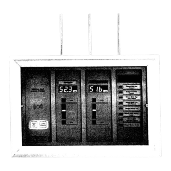
INTRODUCTION The Amico medical gas alarm system (ALERT-1) incorporates the latest digital technology in alarm arid surveillance systems. The system has been designed primarily for user flexibility and reliability. Features include: • Digital read-out for every gas service measured. • Bar-graph display for trend indication. - Page 4 O R R O W E MASTER STATUS MODULE ALERT-1 is factory-calibrated for"Normally Closed Circuit" (NC) operation so that the alarm function will be initiated on an open circuit. In this mode the alarm system will signal both alarm conditions and system malfunctions.
-
Page 5: Installation
B. MODULES CAUTION The circuitry on ALERT-1 contains sophisticated integrated circuits and as such can be damaged by static. When installing the modules, hold the boards by the edges and do not touch any of the components or circuitry on the board. Static discharge to a component can cause the module to malfunction. -
Page 6: Power Module
POWER MODULE 1. POWER MODULE (a) Remove the power module from its box by holding the metallic plate that covers the circuit board. (b) Plug the connector which is located at the end of the tail of the power module into the first (leftmost) receptacle on the motherboard. -
Page 7: Pressure Display Module
P R E S S U R E AND S E N S O R MODULES 2. PRESSURE DISPLAY AND SENSOR MODULES These two modules are installed concurrently. The sensor module contains the transducer which is connected to the brass quick-disconnect. SENSOR M O D U L E NOTE: A L W A Y S HOLD THIS MODULE BY T H E B R A S S QUICK-DICONNECT... -
Page 8: Status Module
STATUS MODULE 3. STATUS MODULE (a) Plug the connector at the end of the tail of the Status module into the appro- priate place on the motherboard. (b) F l i p the status module so that it hangs by its cable just below the box. The circuit with all the components should now be visible. -
Page 9: Electrical Connections
ELECTRICAL C. ELECTRICAL NOTE: POWER SHOULD BE BROUGHTTOTHE UNITONLY AFTER ALLTHE MODULES ARE CONNECTED TO THE MOTHERBOARD. Remove the, transformer cover located at the left hand side of the box by unscrewing the nut at the center of the housing (nearthe fuse). Bring 115 VAC to the appropriately labeled terminal strip. Once the power is applied the display lights up and the buzzer should sound when the "push to test"... -
Page 10: Trouble Shooting
TROUBLE SHOOTING D. TROUBLE SHOOTING Solutions are shown in order of the most probable problem. SOLUTION PROBLEM 1. L I G H T S NOT ILLUMINATED ( a ) C h e c k the fuse by removing the power module. The fuse is directly behind the power module (Fig. -
Page 11: Drawings
DIAGRAMS (Diagrams in Inches) 6 POSITION BOX -.- 0 . 7 5 0 -I- 3 . 3 0 0 ; 1 . - I - " - - ' — - - - - - , 3 . 3 0 0 — • 3 250 - - . - . 6.125 r _ 0.750 1.250... -
Page 12: Wiring Diagrams
WIRING DIAGRAM FOR AREA ALARM Back - Box Mother Board - Ribbon Cable Power Module To Remote Alarm Ribbon Cable High High Sensor Pressure Module Module MP-MOD-L-GAS... - Page 13 WIRING DIAGRAM FOR MASTER ALARM Back - Box Mother Board Ribbon Cable Master Typical examples Module for closed circuit operation. Optional Field Equipment Computer N.C. OXYGEN PRIMARY BULK TANK Interface To Computer Remote LIQUID LEVEL LOW Common Module Monitoring inputs N.C.
- Page 14 WIRING DIAGRAM FOR 120VAC SUPPLY 120VAC Supply 24VDC to Manifold Back ransformer Fuse 1/2 Amp. Rectifier Power Module Connection 24 + to Optional "Remote Alarm" Gt4D + 15 Power Plug MP-MOD-E-POW...
- Page 15 C F I E L D CALIBRATION AREA ALARM The Amico Alert-1 Series of Master and Area Alarms are precision electronic monitoring and alarm instruments that are factory calibrated and set according to the most current N.F.P.A. and CSA standards.
-
Page 16: Power Supply
Calibration Procedure for the Pressure Display Module Calibration Procedure for the Pressure Display Module Setup: Setup: Connect the display PCB to a well calibrated Sensor module in a working frame and Connect the display PCB to a well calibrated Sensor module in a working frame and power supply. - Page 17 1 2 O N 1 1 I I I SW1 N u m e r i c a l d i s p l a y r a n g e s e l e c t SW2 B a r d i s p l a y o p t i o n a l g a i n a d j u s t s e l e c t SW3 S W 5 SW3 N u m e r i c a l d i s p l a y d e c i m a l p o i n t s e l e c t SW4 C a l i b r a t e / o p e r a t e s w i t c h...
- Page 18 Distributed by: Andersen Medical Gas 12 Place Lafi fi tte Madisonville, LA 70447 www.TheMedicalGas.com 1-866-288-3783 Corporation M I C O 8-30 Mural Street, Richmond Hill, Ontario L 4 B 185, CANADA Te l : (905) 764-0800, Fax: (905) 764-0862...
Need help?
Do you have a question about the ALERT-1 and is the answer not in the manual?
Questions and answers